Article

Beyond 100 m Range Mini-LED-Based Visible Light Communication System

by
Zhijian Lv
,
Shuang Wu
,
Junye Zhong
,
Zikun Xu
,
Tiefeng He
,
Jinpeng Tian
,
Linfeng Zheng
,
Haichuan Zhang
,
Wenwei Zhang
and
Muxin Nian
*
Sino-German College of Intelligent Manufacturing, Shenzhen Technology University, Shenzhen 518118, China
*
Author to whom correspondence should be addressed.
Photonics 2025, 12(7), 629; https://doi.org/10.3390/photonics12070629
Submission received: 20 May 2025 / Revised: 17 June 2025 / Accepted: 19 June 2025 / Published: 20 June 2025
(This article belongs to the Section Optical Communication and Network)

Abstract

:
In visible light communication (VLC) systems, lenses are typically used to collimate light at the transmitter. However, due to the wide light emission angle of mini-LEDs, capturing light at large angles using a lens at the transmitter can be challenging. This paper presents a design of a reflective cup at the mini-LED-based VLC transmitter. The redesigned reflective cup can collect most of the light and collimate it, achieving an efficiency of approximately 86% at a distance of 10 m in the simulation. In the experiment, error-free communication was achieved at a distance of 100 m with a data rate of 190 Mbps. To the best of our knowledge, a long-distance VLC system based on mini-LEDs is investigated for the first time. The reflective cup offers advantages, including high efficiency, low cost, and a simple structure. It holds reference value for addressing the issue of limited communication distance in underwater wireless optical communication (UWOC).

1. Introduction

Visible light communication (VLC) is a novel communication mode wherein information is transmitted by modulating the visible spectrum used for illumination [1]. It offers several advantages, such as safety, energy savings, absence of electromagnetic interference, and a high data rate [2,3,4,5]. The collection and development of marine resources are driven by underwater communication [6,7,8,9,10]. VLC is becoming a hot research topic in specific communication scenarios, such as underwater wireless optical communication (UWOC), which has rocketed up in recent years [11,12]. In seawater, light with a wavelength between 450 nm and 550 nm exhibits long attenuation lengths [6], making visible light sources such as LEDs or laser diodes (LDs) common choices for UWOC [13]. Compared to LDs, LEDs have advantages including low cost, long lifespan, safety, low power consumption, and the dual functionality of communication and illumination [14,15]. Mini-LEDs, in comparison to regular LEDs, provide higher bandwidth, making them a good choice for UWOC [16]. In contemporary times, the primary obstacle hindering the development of UWOC is the limited communication distance [17]. Due to the significant attenuation of radio frequency (RF) signal propagation in seawater [18], a high transmission power is required for the light source. Achieving reliable long-distance and high-speed data transmission remains one of the challenges faced by UWOC systems [19]. Many LD-based UWOC systems achieve long-distance communication; at the same time, most LED-based UWOC systems have shorter transmission distances [20,21]. In recent years, VLC based on mini-LEDs has been gradually explored, but it is mostly short-distance. In 2022, Chao Zhang et al. achieved communication at a data rate of 3.8 Gbps using 4-level pulse amplitude modulation (PAM-4) based on single-pixel mini-LED and single avalanche photodiode (APD) over 2 m of distance underwater [16], and Li Xueyang et al. achieved a high-speed mini-LED-based UWOC system operating at a data rate of 5.75 Gbps over 2 m of distance underwater using 8-level pulse amplitude modulation (PAM-8) [22]. In 2023, Ting-Wei Lu et al. built a full duplex VLC system based on a single blue mini-LED acting as transmitter and photodetector simultaneously and achieved communication with a distance of 1.5 m and a data rate of 225 Mbps using 16-ary quadrature amplitude modulation orthogonal frequency division multiplexing (16-QAM-OFDM) [23]. In 2024, Zhiqing Zhao et al. proposed a mini-LED liquid crystal display (LCD) integrated with multiple-input multiple-output (MIMO) VLC, using 460 nm blue mini-LEDs and 10-slot multi-pulse position modulation (MPPM) to achieve 201.6 kbps at 1.1 m in air with forward error correction (FEC)-compliant BER, leveraging backlight segments and camera rolling shutter effect for capacity multiplication [24]. In 2025, Muhammad Hunain Memon et al. presented a dual-band AlGaN/InGaN-QD mini-LED (275 nm deep ultraviolet, DUV/470 nm blue), enabling 540 Mbps (DUV) and 340 Mbps (blue) via OOK in air/water for encrypted communication [25]. In VLC systems, lenses are usually used to collimate the light at the transmitter [26,27,28]. However, because the light emitted by mini-LEDs has a large angle, using a lens to collimate light at the transmitter typically cannot make use of light emitted at large angles [29]. Therefore, using a lens to focus mini-LED light is not efficient, which leads to limited communication distance. To improve the utilization of data rate and realize long-distance communication, this paper designs a reflective cup for a mini-LED-based VLC system, combined with non-return-to-zero on-off keying (NRZ-OOK) modulation, aiming to enhance the system’s communication efficiency and simplify its structure, ultimately enabling a communication range of over 100 m. This paper improves the traditional reflective cup to make it suitable for VLC systems. A detailed comparison of these experimental results is summarized in Table 1, which clearly illustrates the evolution and progress of mini-LED-based VLC systems.

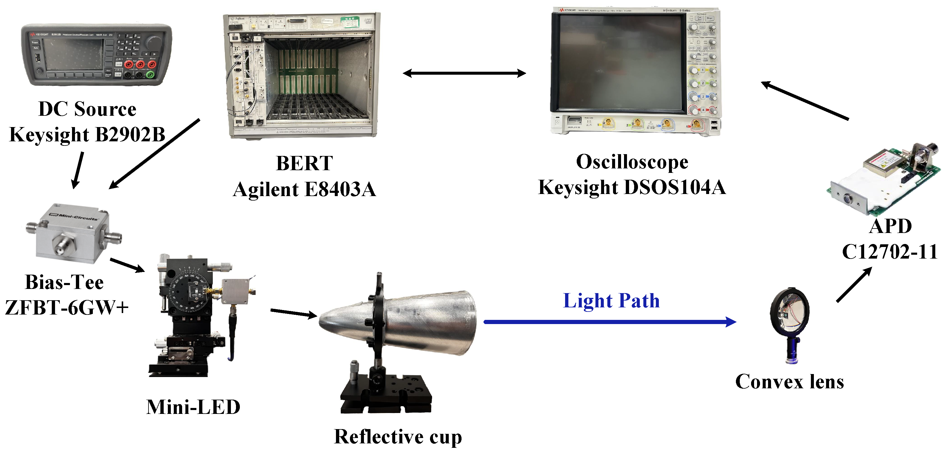
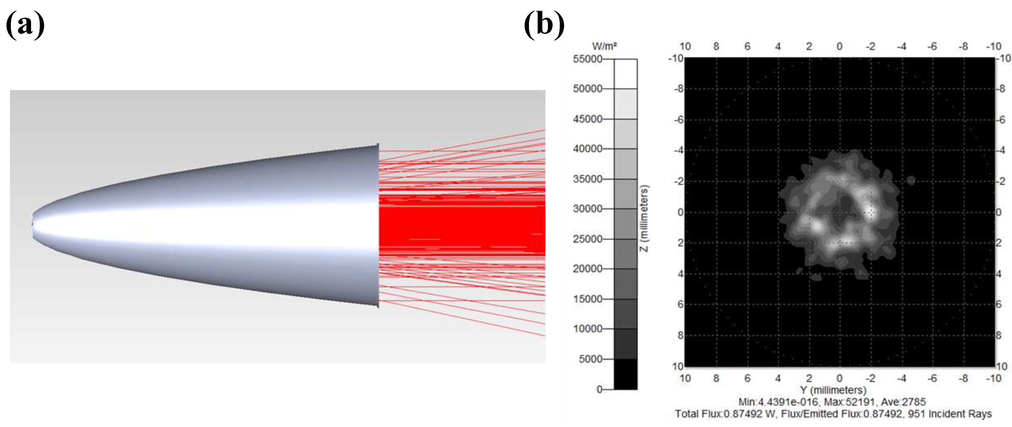
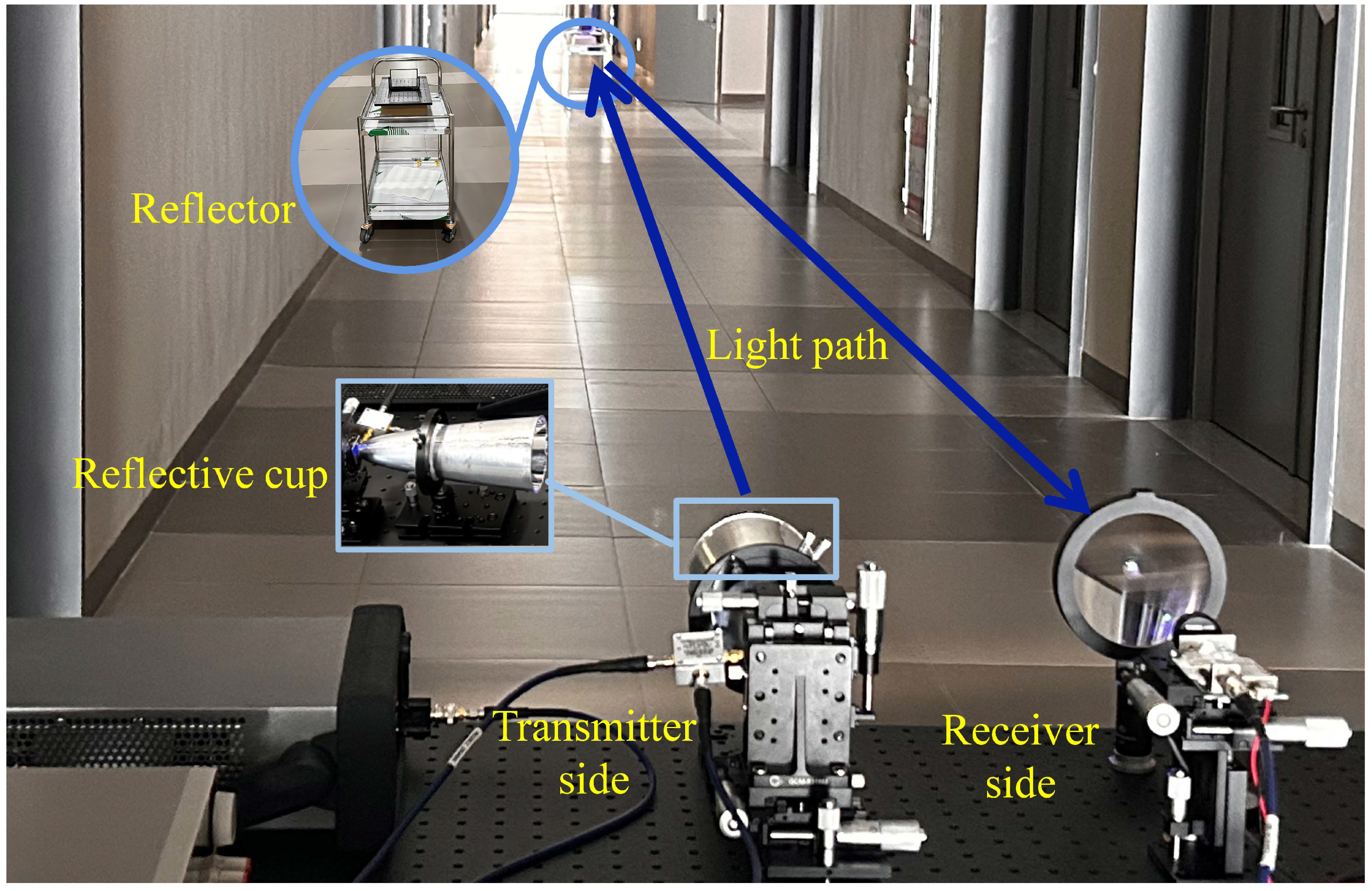
2. Experimental Setup

Figure 1 shows the schematic diagram of the beyond 100 m range VLC system that utilizes a mini-LED and a reflective cup as its key components. The VLC system consists of three parts, as shown in Figure 1, namely the transmitter, light path, and receiver [28,30]. The transmitter includes a direct current (DC) source (Keysight B2902B), bias-tee (Mini-Circuits ZFBT-6GW+), bit error rate tester (BERT) (Agilent E8403A), and mini-LED (HCCLS2021CH103) as the light source. Here, BERT generates a pseudorandom binary sequence (PRBS) as the digital input signal, adds DC through a bias-tee, and then emits an optical signal through a mini-LED. The light path includes a reflective cup, a medium of air, and a convex lens. The light passes through the reflective cup to form a parallel light, which is then focused by the convex lens after passing through the medium. The receiver is an APD (HAMAMATSU c12702-11) and an oscilloscope (Keysight DSOS104A). The focused light is collected by the APD and converted into an electrical signal which will be sent to the oscilloscope or returned to BERT. After the system is built, the waveform of the collected signal can be seen on the oscilloscope, and the eye diagram of the signal can be viewed on the oscilloscope. The signal returned to BERT will be compared with the original signal, and the bit error rate (BER) of the entire channel can be viewed on a personal computer (PC). In addition, a vector network analyzer (KEYSIGHT ENA Network Analyzer E5063A) is used for bandwidth measurement.
In the design of the reflective cup, two aspects are considered. Firstly, regarding the design of the reflection curve, it is essential that the light is capable of being emitted in a parallel manner after being reflected by the reflective cup. According to the characteristics of the reflected light, the expression of the differential equation for the reflection curve is obtained and solved using MATLAB v2023a. Under the given initial value, the function of the reflection curve is as follows:
y = ± 2 x + 1 ( x 0 )
The second aspect to consider is the ratio of the height ( H ) to the diameter ( D ) of the reflective cup. The value of H / D should be medium. Based on Equation (1), the relationship between the value of H / D and H can be derived as follows:
H D = 8 H + 4 H 2 ( H > 0 )
Additionally, the relationship between the divergence angle of the reflective cup ( A ) and H / D can be derived as follows:
A = 2 arctan 1 2 ( H / D )
A large ratio would result in an excessively large size of the reflective cup, while a small ratio would lead to a large divergence angle of the reflective cup, causing it to collect little light. Since the ratio approaches stability as the height increases around 2, it is advisable to control this ratio at approximately 2. This ensures optimal size while maximizing light utilization.
This paper uses SolidWorks v2022 to model the reflective cup and imports the model into TracePro for simulation. In the simulation, the height of the reflective cup model is 20 cm, the diameter is 9 cm, the divergence angle of the reflective cup is approximately 25°, the light source is a point light source, and the field angle distribution is Lambertian. The effect of the reflective cup on the simulation is shown in Figure 2a. Reflected light can be emitted in parallel from the reflective cup, and unreflected light can diverge at angle A, which is consistent with the expected situation. The total irradiance of the light emitted by the LED light source is 1 W. As depicted in Figure 2b, the irradiance received by a planar surface that simulates the light-receiving side of a lens with a diameter of 10 cm and positioned 10 m from the LED light source, which exhibits a total received irradiance of approximately 0.86 W. This corresponds to a reflective cup efficiency of roughly 86% under the specified conditions. The reflective cup sample is shown in Figure 3, which is placed in front of the transmitter to collect light.
The constructed VLC system is depicted in Figure 4, which shows that the system is conducting a long-distance experiment. In the long-distance experiment, in order to reduce the line loss of the signal, a mirror is used in the system to increase the test distance. The light is sent from the transmitter, reflected by the mirror, and returned to the receiver next to the transmitter.

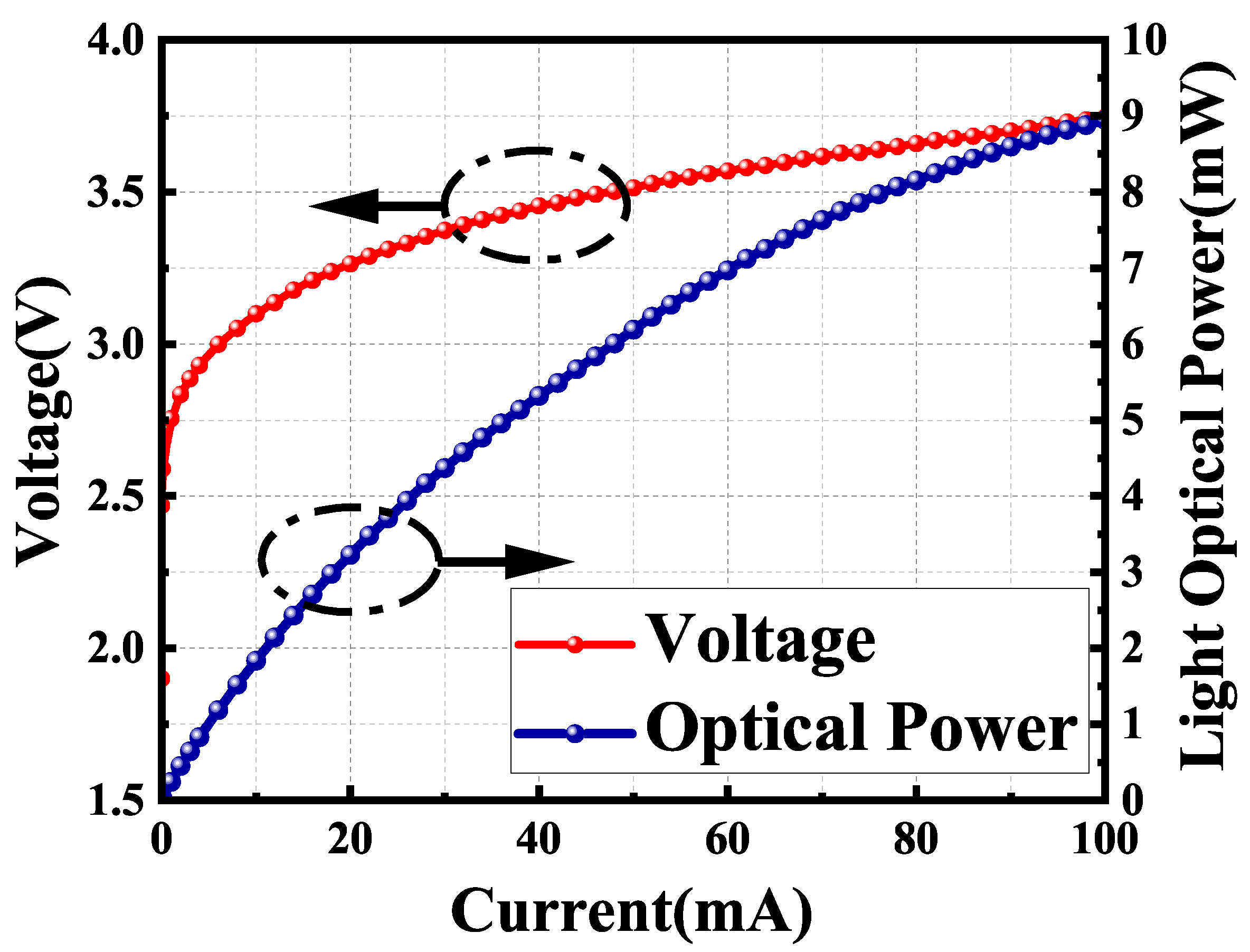
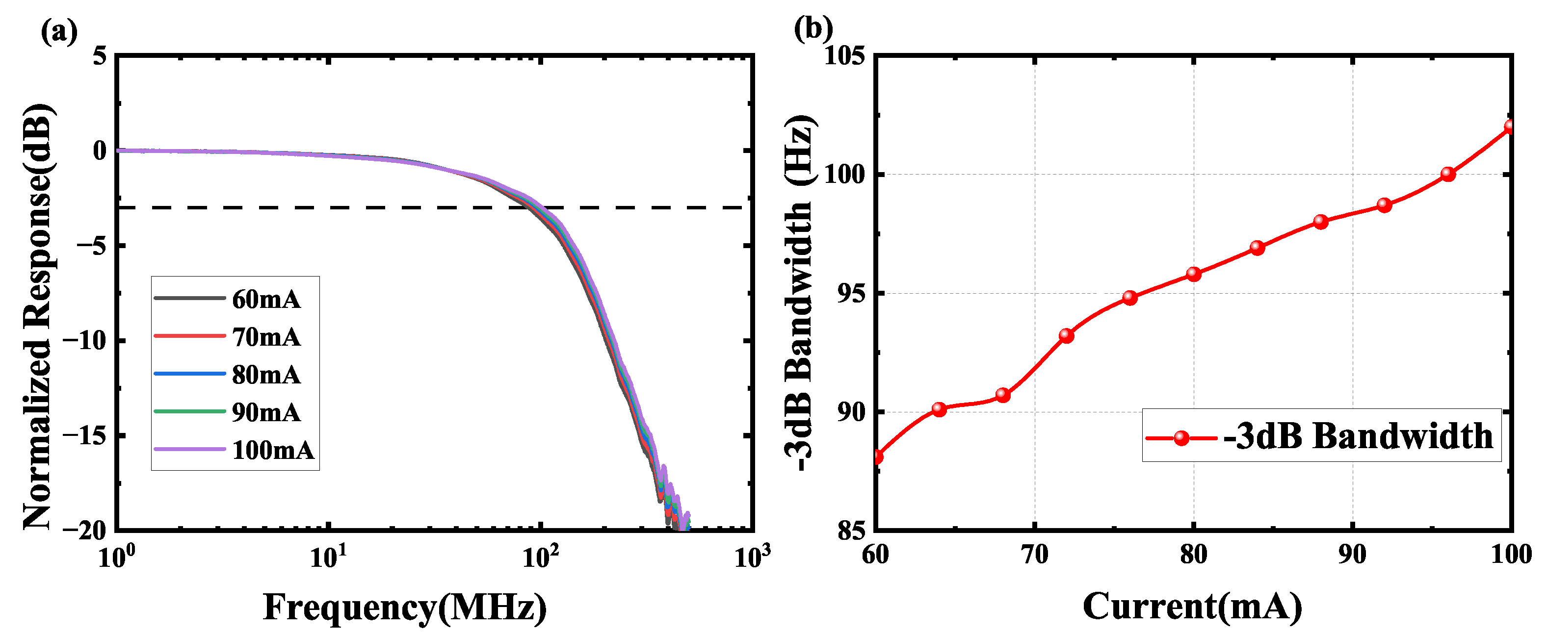
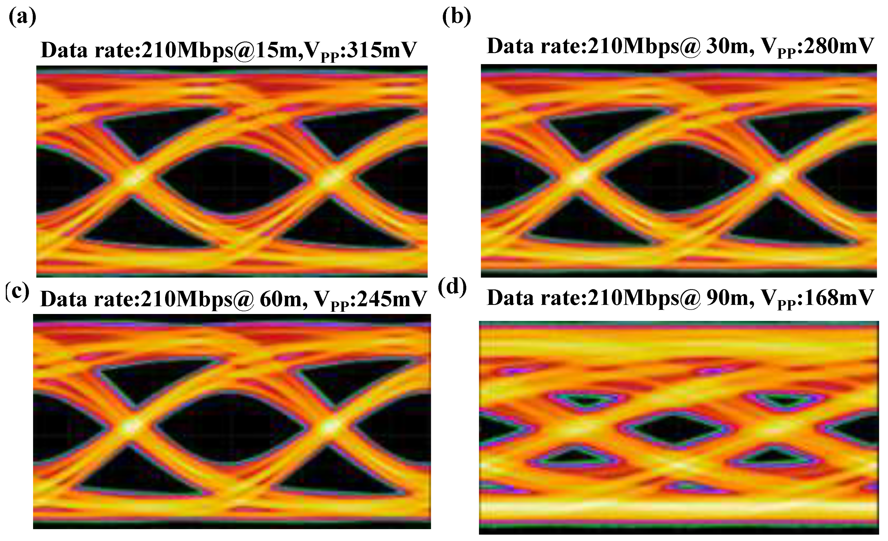
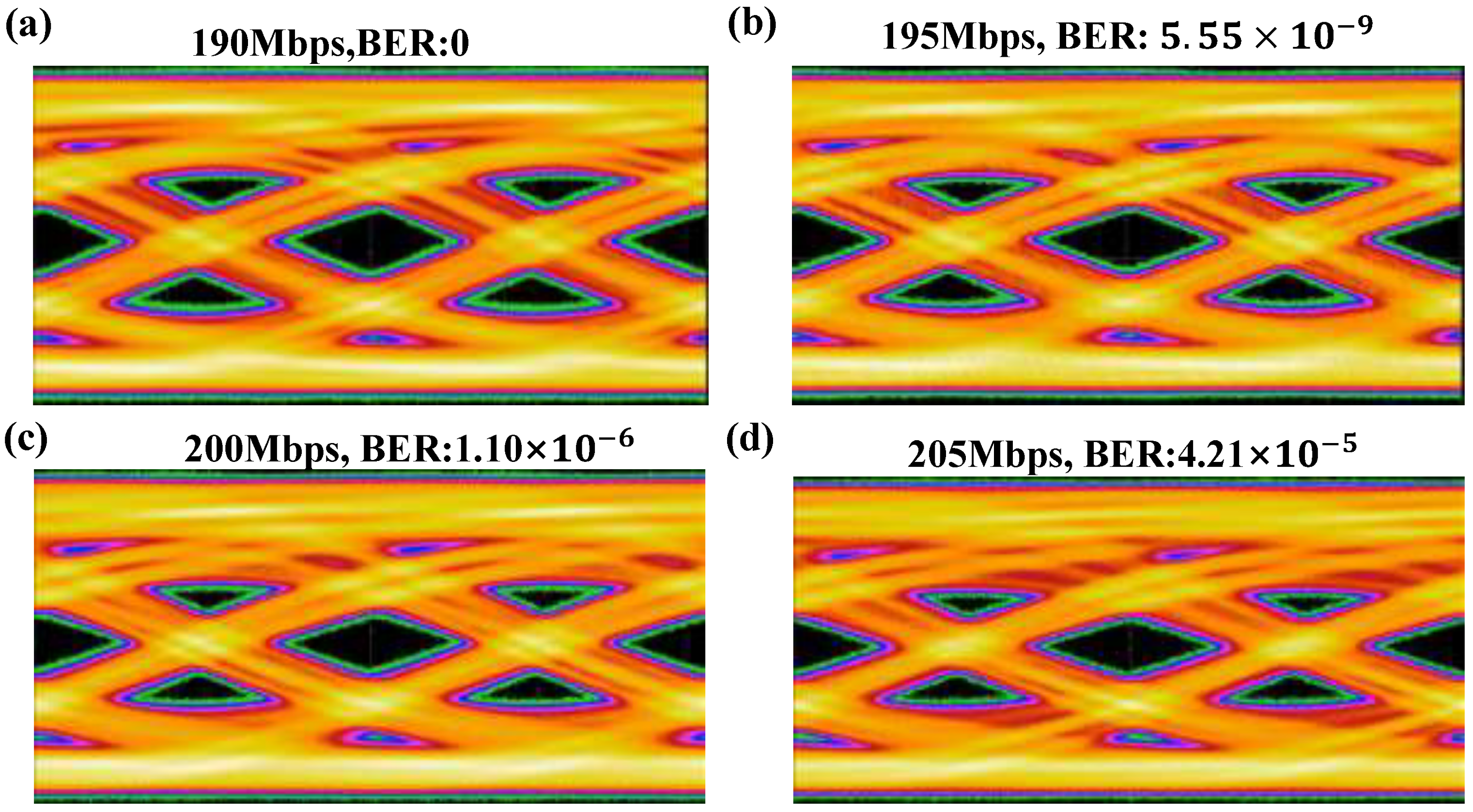
3. Results and Discussion

The optical power–current–voltage (L-I-V) characteristics of the mini-LED used in this experiment are illustrated in Figure 5. The light power is measured at a distance of 1 m from the light source. The threshold voltage of the mini-LED is about 2.5 V. When the voltage is greater than 2.5 V, the current of the mini-LED gradually increases. When the current reaches the maximum current of the mini-LED 100 mA, the voltage is 3.75 V, and the mini-LED has an optical power of 8.95 mW in free space.
In the system, the optimal operating point is shown in Figure 6a,b, and Figure 6 illustrates the changes in the BER based on variations in the DC bias current and alternating current (AC) voltage provided by the BERT. Figure 6a shows that when the AC voltage is 3 V and the system works at a data rate of 210 Mbps, the BER changes with the DC bias current. When the bias current increases from 70 mA to 82 mA, the BER increases from 2.72 × 10 5 gradually, and then decreases to 6.67 × 10 6 . When the bias current continues to increase from 82 mA to 94 mA, the BER will change from 6.67 × 10 6 to 1.67 × 10 5 . On the other hand, Figure 6b shows that, when the DC bias current is 82 mA and the system operates at a data rate of 210 Mbps, the BER changes with the AC voltage. When the AC voltage increases from 2.5 V to 3 V, the BER increases from 6.32 × 10 3 to 6.67 × 10 6 . Therefore, the optimal operating point of the mini-LED in the system is 82 mA DC bias current and 3 V AC voltage. The following experimental results are measured under the optimal operating conditions of a mini-LED.
As shown in Figure 7a, the frequency response of the system under different DC currents is measured at a distance of 1 m. And the variation of the −3 dB bandwidth with DC current is shown in Figure 7b. We conducted tests between a DC current of 60 mA and 100 mA. Obviously, the −3 dB bandwidth of the system increases with increasing DC current between 60 mA and 100 mA. The frequency response of the system drops rapidly after the −3 dB bandwidth frequency. When the DC current is 82 mA, the system’s −3 dB bandwidth is 96.5 MHz, and the highest data rate of 210 Mbps can be achieved for error-free communication over short distances.
Under optimal operating conditions, the variation in optical power with distance is shown in Figure 8, and the experiment is carried out within a distance range of 1–100 m. The optical power received by the APD gradually decreases with increasing distance. Among them, at a distance of 1 m, the optical power is 8.21 mW, while at a distance of 100 m, the optical power drops to 17 μW. The experimental results show that this system can achieve error-free communication with a speed of 210 Mbps within 90 m, and the optical power at 90 m is 21.7 μW.
The eye diagrams for distances of 15 m, 30 m, 60 m, and 90 m are shown in Figure 9, with their corresponding Vpp values being 315 mV, 280 mV, 245 mV, and 168 mV, respectively. At a distance of 100 m and a data rate of 205 Mbps, the system experiences a small number of bit errors. Error-free communication can be achieved at a maximum data rate of 190 Mbps. Figure 10 and Figure 11 show the BER and eye diagrams at different data rates at a distance of 100 m.

4. Conclusions

In this paper, we establish a VLC system based on a mini-LED with a reflective cup that achieves a communication range beyond 100 m. The redesigned reflective cup effectively collects and collimates most of the light, enabling error-free communication at a distance of 90 m with a data rate of 210 Mbps, and at 100 m with a data rate of 190 Mbps. As far as we know, this is the first investigation of a long-distance VLC system utilizing a mini-LED. The reflective cup offers advantages like excellent efficiency, affordability, and a straightforward design. This study provides significant reference value for UWOC systems, which includes improving the efficiency of systems, increasing the communication distance, and reducing costs and complexity.

Author Contributions

Conceptualization, Z.L.; methodology, Z.L.; software, T.H.; validation, J.T.; formal analysis, L.Z.; investigation, J.Z. and Z.L.; resources, Z.L.; data curation, Z.X.; writing—original draft preparation, S.W.; writing—review and editing, Z.L.; visualization, S.W.; supervision, W.Z.; project administration, H.Z.; funding acquisition, M.N. All authors have read and agreed to the published version of the manuscript.

Funding

Guangdong Provincial Engineering Technology Research Center for Materials for Advanced MEMS Sensor Chip (Award No. 2022GCZX005).

Data Availability Statement

Data underlying the results presented in this paper are not publicly available at this time but may be obtained from the authors upon reasonable request.

Acknowledgments

The authors would like to thank SZTU-ZHT United Lab for providing the testing facilities.

Conflicts of Interest

The authors declare no conflicts of interest.

References

  1. Lv, Z.; He, G.; Qiu, C.; Fan, Y.; Wang, H.; Liu, Z. CMOS monolithic photodetector with a built-in 2-dimensional light direction sensor for laser diode based underwater wireless optical communications. Opt. Express 2021, 29, 16197–16204. [Google Scholar] [CrossRef] [PubMed]
  2. Rehman, S.U.; Ullah, S.; Chong, P.H.J.; Yongchareon, S.; Komosny, D. Visible Light Communication: A System Perspective—Overview and Challenges. Sensors 2019, 19, 1153. [Google Scholar] [CrossRef] [PubMed]
  3. Jung, E.K.; Ahn, S.H.; Hong, S.; Im, H.; Kim, Y.S. Micro Light-Emitting Diode Pixel Circuit Based on Indium–Gallium–Zinc Oxide Thin-Film Transistors Using Pulse Width Modulation. IEEE Electron Device Lett. 2023, 44, 1484–1487. [Google Scholar] [CrossRef]
  4. Chai, Y.; Yin, X.; Han, J.; Ke, S.; Yang, K.; Lin, Y.; Chen, Z.; Guo, Z.; Wan, C. Transparent Bamboo as an Optical Management Material to Improve Color Uniformity of Light-Emitting Diodes. IEEE Trans. Electron Devices 2024, 71, 7616–7620. [Google Scholar] [CrossRef]
  5. Du, Z.; Wang, K.; Sun, J.; Guo, W.; Wu, C.; Lin, C.; Yan, Q. Ultrahigh Color Conversion Efficiency Nano-Light-Emitting Diode With Single Electrical Contact. IEEE Trans. Electron Devices 2023, 70, 1156–1161. [Google Scholar] [CrossRef]
  6. Zhu, S.; Chen, X.; Liu, X.; Zhang, G.; Tian, P. Recent progress in and perspectives of underwater wireless optical communication. Prog. Quantum Electron. 2020, 73, 100274. [Google Scholar] [CrossRef]
  7. Kaushal, H.; Kaddoum, G. Underwater Optical Wireless Communication. IEEE Access 2016, 4, 1518–1547. [Google Scholar] [CrossRef]
  8. Xu, J. Underwater wireless optical communication: Why, what, and how? Chin. Opt. Lett. 2019, 17, 100007. [Google Scholar] [CrossRef]
  9. Lv, Z.; He, G.; Yang, H.; Chen, R.; Li, Y.; Zhang, W.; Qiu, C.; Liu, Z. The Investigation of Underwater Wireless Optical Communication Links Using the Total Reflection at the Air-Water Interface in the Presence of Waves. Photonics 2022, 9, 525. [Google Scholar] [CrossRef]
  10. Aman, W.; Al-Kuwari, S.; Muzzammil, M.; Rahman, M.M.U.; Kumar, A. Security of underwater and air–water wireless communication: State-of-the-art, challenges and outlook. Ad Hoc Netw. 2023, 142, 103114. [Google Scholar] [CrossRef]
  11. Oubei, H.M.; Shen, C.; Kammoun, A.; Zedini, E.; Park, K.H.; Sun, X.; Liu, G.; Kang, C.H.; Ng, T.K.; Alouini, M.S.; et al. Light based underwater wireless communications. Jpn. J. Appl. Phys. 2018, 57, 08PA06. [Google Scholar] [CrossRef]
  12. Lv, Z.; Liu, X.; Wu, S.; Zhang, W.; Yue, C.P.; Liu, Z. Massive GaN micro-LED array based underwater wireless optical communication. Opt. Express 2025, 33, 19527–19534. [Google Scholar] [CrossRef] [PubMed]
  13. Sticklus, J.; Hoeher, P.A.; Röttgers, R. Optical Underwater Communication: The Potential of Using Converted Green LEDs in Coastal Waters. IEEE J. Ocean. Eng. 2019, 44, 535–547. [Google Scholar] [CrossRef]
  14. Haydaroglu, I.; Ozgun, M.T.; Mutlu, S. Optically Powered Optical Transmitter Using a Single Light-Emitting Diode. IEEE Trans. Circuits Syst. Regul. Pap. 2017, 64, 2003–2012. [Google Scholar] [CrossRef]
  15. Cao, H.; Lin, S.; Ma, Z.; Li, X.; Li, J.; Zhao, L. Color Converted White Light-Emitting Diodes With 637.6 MHz Modulation Bandwidth. IEEE Electron Device Lett. 2019, 40, 267–270. [Google Scholar] [CrossRef]
  16. Zhang, C.; Wei, Z.; Li, X.; Li, Y.; Wang, L.; Wang, L.; Fu, H.Y.; Yang, Y. 3.8 Gb/s PAM-4 UOWC System Over a 2-m Underwater Channel Enabled by a Single-Pixel 175-μm GaN-Based Mini-LED. IEEE Photonics J. 2022, 14, 7323207. [Google Scholar] [CrossRef]
  17. Miramirkhani, F.; Uysal, M. Visible Light Communication Channel Modeling for Underwater Environments With Blocking and Shadowing. IEEE Access 2018, 6, 1082–1090. [Google Scholar] [CrossRef]
  18. Qureshi, U.M.; Shaikh, F.K.; Aziz, Z.; Shah, S.M.Z.S.; Sheikh, A.A.; Felemban, E.; Qaisar, S.B. RF Path and Absorption Loss Estimation for Underwater Wireless Sensor Networks in Different Water Environments. Sensors 2016, 16, 890. [Google Scholar] [CrossRef]
  19. Huang, X.; Yang, F.; Song, J. Hybrid LD and LED-based underwater optical communication: State-of-the-art, opportunities, challenges, and trends. Chin. Opt. Lett. 2019, 17, 2–10. [Google Scholar] [CrossRef]
  20. Shen, J.; Wang, J.; Yu, C.; Chen, X.; Wu, J.; Zhao, M.; Qu, F.; Xu, Z.; Han, J.; Xu, J. Single LED-based 46-m underwater wireless optical communication enabled by a multi-pixel photon counter with digital output. Opt. Commun. 2019, 438, 78–82. [Google Scholar] [CrossRef]
  21. Han, B.; Zhao, W.; Zheng, Y.; Meng, J.; Wang, T.; Han, Y.; Wang, W.; Su, Y.; Duan, T.; Xie, X. Experimental demonstration of quasi-omni-directional transmitter for underwater wireless optical communication based on blue LED array and freeform lens. Opt. Commun. 2019, 434, 184–190. [Google Scholar] [CrossRef]
  22. Li, X.; Cheng, C.; Wei, Z.; Fu, H.; Yang, Y.; Hu, W. Net 5.75 Gbps/2 m Single-Pixel Blue Mini-LED Based Underwater Wireless Communication System Enabled by Partial Pre-Emphasis and Nonlinear Pre-Distortion. J. Light. Technol. 2022, 40, 6116–6122. [Google Scholar] [CrossRef]
  23. Lu, T.W.; Huang, Y.; Lai, S.Q.; Lin, S.H.; Liu, S.B.; Fan, X.T.; Lu, Y.J.; Lin, Y.; Chen, Z.; Wu, T.Z. Full-Duplex Visible Light Communication System Based on Single Blue Mini-LED Acting as Transmitter and Photodetector Simultaneously. J. Light. Technol. 2023, 41, 2639–2649. [Google Scholar] [CrossRef]
  24. Zhao, Z.; Qiu, Y.; Zou, G.; Liu, Y.; Weng, J.; Yang, B.R.; Qin, Z. High-capacity MIMO visible light communication integrated into mini-LED LCDs. Opt. Express 2024, 32, 14876–14891. [Google Scholar] [CrossRef]
  25. Memon, M.H.; Yu, H.; Luo, Y.; Gao, Z.; Kang, Y.; Yue, F.; Sun, H. Ultraviolet-Visible Dual-band Mini-Sized Light Emitting and Detecting Diode Toward Optical Communication. J. Light. Technol. 2025, 1–5. [Google Scholar] [CrossRef]
  26. Apolo, J.A.; Ortega, B.; Almenar, V. Hybrid POF/VLC Links Based on a Single LED for Indoor Communications. Photonics 2021, 8, 254. [Google Scholar] [CrossRef]
  27. Chen, Y.; Wen, S.; Wu, Y.; Ren, Y.; Guan, W.; Zhou, Y. Long-range visible light communication system based on LED collimating lens. Opt. Commun. 2016, 377, 83–88. [Google Scholar] [CrossRef]
  28. Lu, Z.; Tian, P.; Fu, H.; Montes, J.; Huang, X.; Chen, H.; Zhang, X.; Liu, X.; Liu, R.; Zheng, L.; et al. Experimental demonstration of non-line-of-sight visible light communication with different reflecting materials using a GaN-based micro-LED and modified IEEE 802.11ac. Aip Adv. 2018, 8, 105017. [Google Scholar] [CrossRef]
  29. Ye, Z.T.; Chen, Y.L.; Chiu, C.C.; Hu, C.C. Zero-optical-distance mini-LED backlight with light-guiding microstructure lens for extra-thin, large-area notebook LCDs. Opt. Express 2023, 31, 43600–43614. [Google Scholar] [CrossRef]
  30. Lv, Z.; He, G.; Qiu, C.; Liu, Z. Investigation of Underwater Wireless Optical Communications Links With Surface Currents and Tides for Oceanic Signal Transmission. IEEE Photonics J. 2021, 13, 7300508. [Google Scholar] [CrossRef]
Figure 1. The diagram of the beyond 100 m range VLC system with a mini-LED and a reflective cup.
Photonics 12 00629 g001
Figure 2. (a) Reflective cup simulation. (b) Total irradiance map.
Photonics 12 00629 g002
Figure 3. Reflective cup sample.
Photonics 12 00629 g003
Figure 4. The real scenario of the experiment.
Photonics 12 00629 g004
Figure 5. Voltage versus current and optical power versus current characteristics of the mini-LED.
Photonics 12 00629 g005
Figure 6. (a) The optimization of BER for different DC bias currents when AC voltage is 3 V at a data rate of 210 Mbps. (b) The optimization of BER for different AC voltages when DC bias currents is 82 mA at a data rate of 210 Mbps.
Photonics 12 00629 g006
Figure 7. (a) Frequency response of the system at different DC bias currents. (b) Bandwidth of the system at different DC bias currents.
Photonics 12 00629 g007
Figure 8. Optical power at the receiver at different distances.
Photonics 12 00629 g008
Figure 9. (a) Eye diagram with a distance of 15 m at a data rate of 210 Mbps; (b) Eye diagram with a distance of 30 m at a data rate of 210 Mbps; (c) Eye diagram with a distance of 60 m at a data rate of 210 Mbps; (d) Eye diagram with a distance of 90 m at a data rate of 210 Mbps.
Photonics 12 00629 g009
Figure 10. BER at different data rates at a distance of 100 m.
Photonics 12 00629 g010
Figure 11. (a) Eye diagram with a data rate of 190 Mbps at a distance of 100 m; (b) Eye diagram with a data rate of 195 Mbps at a distance of 100 m; (c) Eye diagram with a data rate of 200 Mbps at a distance of 100 m; (d) Eye diagram with a data rate of 205 Mbps at a distance of 100 m.
Photonics 12 00629 g011
Table 1. Comparison of mini-LED-based optical communication systems.
GroupType of Light SourceModulation SchemeDistanceChannelData Rate
Chao Zhang et al. [16]Single blue mini-LEDPAM-42 mPure water3.8 Gbps
Li Xueyang et al. [22]Single blue mini-LEDPAM-82 mPure water5.75 Gbps
Ting-Wei Lu et al. [23]Single blue mini-LED16-QAM-OFDM1.5 mFree space225 Mbps
Zhiqing Zhao et al. [24]Blue mini-LEDsMPPM1.1 mFree space201.6 kbps
Muhammad Hunain Memon et al. [25]Single blue mini-LEDOOK∼mPure water340 Mbps
This workSingle blue mini-LEDNRZ-OOK>100 mFree space190 Mbps
Disclaimer/Publisher’s Note: The statements, opinions and data contained in all publications are solely those of the individual author(s) and contributor(s) and not of MDPI and/or the editor(s). MDPI and/or the editor(s) disclaim responsibility for any injury to people or property resulting from any ideas, methods, instructions or products referred to in the content.

