1. Introduction
In the information age, the exponential growth in data transmission demand has increasingly exposed the limitations of quartz glass-based optical fibers. These materials suffer from inherent drawbacks, including high chromatic dispersion, pronounced fiber nonlinearity, and a low damage threshold [
1], which collectively render them incapable of meeting the escalating requirements for transmission capacity and severely impede the advancement of fiber optic technology. To address the demands of next-generation optical network communications for low-latency, high-speed, and large-capacity data transfer, hollow-core optical fibers (HCFs) have emerged as a promising solution to enhance optical signal propagation speeds [
2,
3,
4,
5,
6]. Unlike conventional solid-core fibers, HCFs employ fundamentally distinct light-guiding mechanisms based on suppressed coupling [
7,
8] and anti-resonant reflection models [
9], diverging entirely from the total internal reflection (TIR) principle of traditional single-mode fibers. Through precisely engineered microstructured claddings—such as photonic bandgap or anti-resonant structures—these fibers confine the light field predominantly within the air-filled core, rather than relying on silica–glass interface reflections [
10]. This design leverages the nonlinear refractive index of air, which is approximately three orders of magnitude lower than that of silica glass, endowing HCFs with superior performance attributes.
The unique light-guiding mechanism of HCFs theoretically enables ultra-low transmission loss, minimal latency, negligible nonlinearity, near-zero dispersion, high power-handling capability, and robust radiation/thermal stability [
3]. These exceptional properties position HCFs for wide-ranging applications, particularly in high-capacity optical communications, where they can surmount the fundamental bottlenecks of conventional fiber technology [
11,
12,
13,
14]. Recent years have witnessed substantial research momentum and breakthroughs in HCF development, underscoring their transformative potential in next-generation optical networks.
Current research on hollow-core optical fibers can be divided into two main types: hollow-core photonic bandgap fibers (HC-PBGFs) and hollow-core anti-resonant fibers (HC-ARFs). These two approaches differ significantly in terms of their structures and guiding mechanisms. In 1998, Knight et al. designed and successfully fabricated the world’s first HC-PBGF [
15,
16,
17], relying on the photonic bandgap effect for guidance. Despite the continuous improvements that have been made in this area, HC-PBGFs have certain limitations, such as the excessive SSL caused by excessive contact between light and glass materials [
18], resulting in fiber losses reaching 1.2 dB/km. HC-PBGFs are highly sensitive to structural parameters, and minor changes in the cladding structure can significantly affect the fiber’s bandgap structure, thereby influencing the confinement loss (CL) and bandwidth [
19,
20]. In addition, HC-PBGFs exhibit a strong and significant coupling between the core and glass cladding modes [
21], providing only a narrow low-loss bandwidth. In contrast, HC-ARFs rely on anti-resonance reflection principles [
22,
23] and the suppression of coupling modes for guidance [
10]; this approach has the advantages of a simple structure, large transmission bandwidth, and low coupling of mode energy to the cladding. Consequently, recent research on hollow-core optical fibers has focused on HC-ARFs.
As the first HC-ARF to be studied, the Kagome fiber proposed by Benabid et al. was the first to be based on the suppression of coupling modes [
24,
25], and it achieved a loss of 13.9 dB/km at 1.55 μm [
26]. In 2014, the University of Southampton introduced a nested, nodeless, hollow-core, anti-resonant fiber that consisted of six non-contacting nested tubes. In theory, this HC-ARF was able to achieve lower losses than single-mode, solid-core fibers [
22]. In 2016, Subhasis proposed that, compared to similar circular tube structures, elliptical tube structures would have smaller confinement losses [
27], and two years later, Gao reported an experimentally validated anti-resonant fiber based on joint tubes, with a minimum loss of 2 dB/km at 1.512 μm [
12]. A five-tube nested, anti-resonant, negativecurvature fiber was proposed, with transmission losses of below 1 dB/km between 1.33 μm and 1.66 μm in 2019 [
28]. In 2021, the authors of ref. [
29] present an anisotropic nested anti-resonant fiber (AN-ARF) with a hybrid cladding of elliptical tubes nested within the circular tubes. The results show the lowest confinement loss to be 0.0007 dB/km at 1.06 μm, and the structure maintained a loss of less than 0.003 dB/km over a bandwidth of 670 nm (0.90 μm to 1.57 μm). In the same year, a nested, anti-resonant, nodeless, hollowcore fiber with five cladding elements was introduced that exhibited an extremely low transmission loss of 0.22 dB/km at 1.55 μm [
30]. At the same time, based on the complex element, several HC-ARFs with low CL have been developed. A double-nested antiresonant non-node fiber (DNANF) was designed in 2022, with a very low transmission loss of 0.174 dB/km. Notably, DNANF effectively suppressed the high-order core mode LP
11, and the extinction ratio of the higher-order modes was greater than 1000, giving it excellent single-mode performance [
31]. In 2023, Nanyang Technological University proposed an anti-resonant hollow-core fiber with ultra-low loss and outstanding single-mode characteristics at 1.55 μm. By introducing strong coupling between the core high-order modes and cladding hole modes, the extinction ratio for the high-order modes reached 8 × 10
5 [
32].
Due to the bandwidth limitations of PBGFs, recent research on hollow-core optical fibers has mainly focused on reducing the losses in straight fibers and the bending fibers of ARFs and on expanding into new transmission bandwidths. ARFs can support several high-order core modes as well as the fundamental mode. An increase in the loss for the high-order modes can be achieved by intentionally inducing coupling between high-order core modes and cladding hole modes [
33,
34,
35]. In tubular hollow-core fiber structures, this can be achieved by optimizing the ratio of the core size to the cladding structure size. In addition, studies have shown that, by introducing nested layer elements into the cladding to adjust the gaps between elements, coupling between high-order modes in the core and cladding modes can be achieved, thereby enhancing the single-mode characteristics of the fiber. At the same time, the spacing between various elements of the fiber and the size of the nested layers may significantly affect the performance of the fiber. Hence, the size of each fiber element and the rational arrangement of elements are crucial to ensure that ARFs have excellent loss and bandwidth performance.
In this study, we propose a novel hybrid anti-resonant hollow-core fiber with double semi-circular tubes sandwiching elliptic tubes (SSE-ARF). Compared to the double-nested structure (DNANF), the CL of this structure is reduced by two orders of magnitude. Our new fiber structure has excellent light-guiding characteristics, with ultra-low losses, good single-mode characteristics, and outstanding bending performance. We first confirm the rationality of the structure through appropriate calculations and then carry out numerical studies of the influence of various structural parameters on the performance of the SSE-ARF. Furthermore, we compare the performance of our proposed SSE-ARF with other conventional hollow-core fibers such as DNANF to validate its superior performance. Finally, we perform an analysis of manufacturing tolerances for the proposed design, which indicates that our SSE-ARF can achieve good performance in terms of robustness. With these characteristics, SSE-ARF shows great potential for applications in fiber optic communication scenarios, such as high-speed backbone networks, metropolitan area networks, and data center interconnections. In addition, due to their various advantages over single-mode fibers, hollow-core fibers also have the potential for applications in other fields, such as sensing and lasers, and further research on them is needed. It is expected to become one of the key technologies driving the development of next-generation fiber-optic communication technologies.
2. Principle and Fiber Geometry
In an ARF, a negative curvature of the core boundary (where the curvature direction of the core boundary is opposite to the curvature direction of the core circle) can be used to reduce the CL [
22]. Hence, circular tubes have been widely used in ARFs. In order to obtain a further increase in the negative curvature of the core boundary, an elliptical tube is selected for the proposed SSE-ARF, because, when the long axis of the elliptical tube is equal to the radius of the circular tube, the corresponding negative curvature at both ends of the long axis of the elliptical tube element is larger than that of the circular tube element. Existing hollow-core anti-resonant fibers with elliptical tube structures, such as AN-ARFs [
29], possess excellent low-loss and bending performance, but show weak single-mode characteristics with a value for the HOMER of much lower than 1000. The HOMER is defined as the ratio between the
and the high-order mode and represents the single-mode characteristic of the fiber [
36,
37]. In general, when the HOMER exceeds 1000, the fiber has excellent single-mode characteristics [
31]. In this paper, we use the ratio of the fundamental mode loss to the lowest higher-order mode loss to calculate the HOMER. For simplicity, we refer to the higher-order mode with the minimum loss as the
mode in what follows.
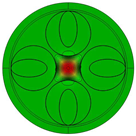
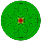
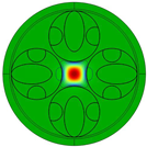
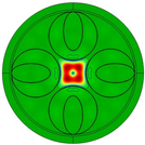
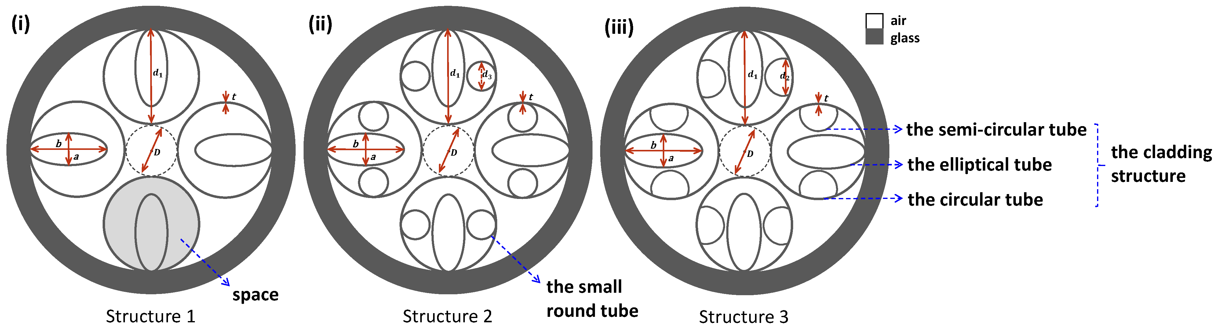
Initially, we altered an AN-ARF by using a cladding with a four-tube structure, which is marked as Structure 1 in
Figure 1(i). From the
mode field plot in
Table 1, it can be observed that most of the
mode is confined within the core, indicating a low single-mode characteristic. To improve the single-mode characteristic, we placed a small round tube on each side of every elliptical tube, as shown in
Figure 1(ii), to form Structure 2. The presence of these small round tubes allows the cladding structure to support modes that can couple with higher-order modes, thereby enhancing the single-mode performance, as evidenced by the
mode field patterns for Structure 2 in
Table 1. However, the small round tubes in Structure 2 only occupy limited space in the circular tube and create a large blank space for the transmission of the higher-order modes. We therefore replaced these with semi-circular tubes, resulting in Structure 3, as shown in
Figure 1(iii). The diagram illustrates that semi-circular tubes can occupy a larger structural space. In addition, the high-order mode field patterns for Structure 3 in
Table 1 show that the semi-circular tubes facilitate better coupling of higher-order modes into the cladding structure, resulting in greatly superior single-mode performance compared to Structure 2. Consequently, we selected Structure 3 for subsequent optimization. This structure is composed of double semi-circular tubes sandwiching elliptical tubes, and is therefore referred to as an SSE-ARF.
Figure 1(iii) depicts the cross-section of the proposed SSE-ARF, which consists of four cladding structures forming an anti-resonant layer. Each cladding structure is composed of an outermost circular tube element, an internally nested elliptical tube element, and semi-circular tube elements on both sides. The gray area represents glass material with a refractive index determined by the Sellmeier formula [
38], while the white area represents air with a refractive index of one. The Sellmeier formula is as follows:
where
represents the operating wavelength of the optical fiber. The geometric shape of the fiber is determined by the core diameter (
D), the thickness (
t) of the cladding element, the diameter (
) of the round tube element, the diameter (
) of the semi-circular tube element, the major axis length (
b), and the minor axis length (
a) of the elliptical tube elements from
Figure 1(iii). The value of
t is calculated using the following formula [
39]:
where
represents the operating wavelength,
M represents the order of the anti-resonance, and
and
are the refractive indices of glass and air, respectively. As the wavelength of light changes from the anti-resonant to the resonant wavelength, the binding ability of the glass wall to the light gradually weakens. This leads to the light gradually leaking to the other side of the glass wall, causing a gradual increase in the confinement loss. As the wavelength of light gradually changes from the resonant to the anti-resonant wavelength, the opposite process occurs. This means that ARFs have multiple passbands, with each value of
M corresponding to a different passband. A value of
M = 1 is taken here to broaden the operational bandwidth [
39]. We set
= 1.55 μm to ensure the communication band of the fiber is between the high-loss resonant wavelengths, thereby achieving lower losses [
22]. We ultimately determined the value of
t as 0.36 μm.
The remaining structural parameters need to be determined individually. As part of the parameter optimization process, we first determine the core diameter and subsequently normalize
to
D, denoted as
. Following this, we normalize the other parameters to
, denoted as
,
, and
. The details of the optimization process are discussed in
Section 3 of this paper. In addition, to match the practical application scenario for the fiber, the penetration depth of the connecting portions between each cladding element is set to
t/2 [
4].
3. Parameter Optimization and Discussion
The design and investigation of the optical fiber characteristics were carried out using the COMSOL Multiphysics 6.0 simulation platform. When selecting the structural parameters of the SSE-ARF, we employed the Wave Optics Module (Electromagnetic Waves, Frequency Domain) in COMSOL for modal analysis. This module models the problem by solving Maxwell’s equations, taking into account material properties, boundary conditions, and appropriate mesh generation. To ensure accurate discretization of the hollow-core fiber, the maximum element sizes in air and thin glass regions were typically set to
/4 and
/6 [
40], respectively (where
denotes the operating wavelength). Modal analysis, as the core tool in wave optics computations, enables the exploration of modal characteristics in complex waveguide structures. Through this analysis, the modal properties of the investigated fiber structure can be determined. The complete simulation workflow in COMSOL can be summarized as follows: selecting the physics interface and study type, defining the geometry, specifying materials, setting boundary and initial conditions, generating a finite element mesh, choosing a solver, and visualizing the results. Given the substantial computational burden of this method, certain improvements were implemented during the optimization process to reduce resource consumption.
The control variable analysis method is the most commonly used approach for optimizing the structural parameters of optical fibers [
32]. Its core principle involves keeping other parameters constant while determining the optimal values of the fiber’s structural parameters one by one. Additionally, to further reduce the computational burden, we analyzed the structural parameters of the fiber shown in
Figure 1(iii) and employed a method that prioritizes the main components. This method was used to first determine the values of the core diameter
D and thickness
t, which have a significant impact on the fiber structure. Subsequently, the remaining parameters, including the circular tube diameter
, semi-circular tube diameter
, and the major axis length
b and minor axis length
a of the elliptical tube, were grouped in pairs. The grouped parameters were then subjected to a unified normalization and scanning process. This approach not only reduces the computational and analytical workload but also allows the results to be presented as more intuitive performance pseudo-color maps. The detailed operational procedures are described in the following sections.
3.1. Core Diameter
Initially, we consider the size of the fiber core diameter
D, where, in general, an increase in
D helps reduce the CL. The CL is calculated as [
41]
where
represents the imaginary part of the effective refractive index, and
is the free space wavelength. However, enlarging
D also increases the overall cross-sectional area of the fiber, which is unfavorable for subsequent splicing operations with single-mode fibers. Therefore, the selection of an appropriate core size is crucial. We set
= 1.9 to ensure a relatively small distance between adjacent cladding structures, minimizing light leakage. The other parameters are set to
= 0.33,
= 0.4, and
= 0.8. Under these conditions, the ellipticity of the elliptical tube element is two, which ensures a relatively low CL. Because the selected cladding structure parameters may not guarantee optimal performance for the fiber at various core diameters, the fiber loss curve and the HOMER curve are not monotonic as
D changes, although a general trend towards reduction in CL is seen as
D is increased.
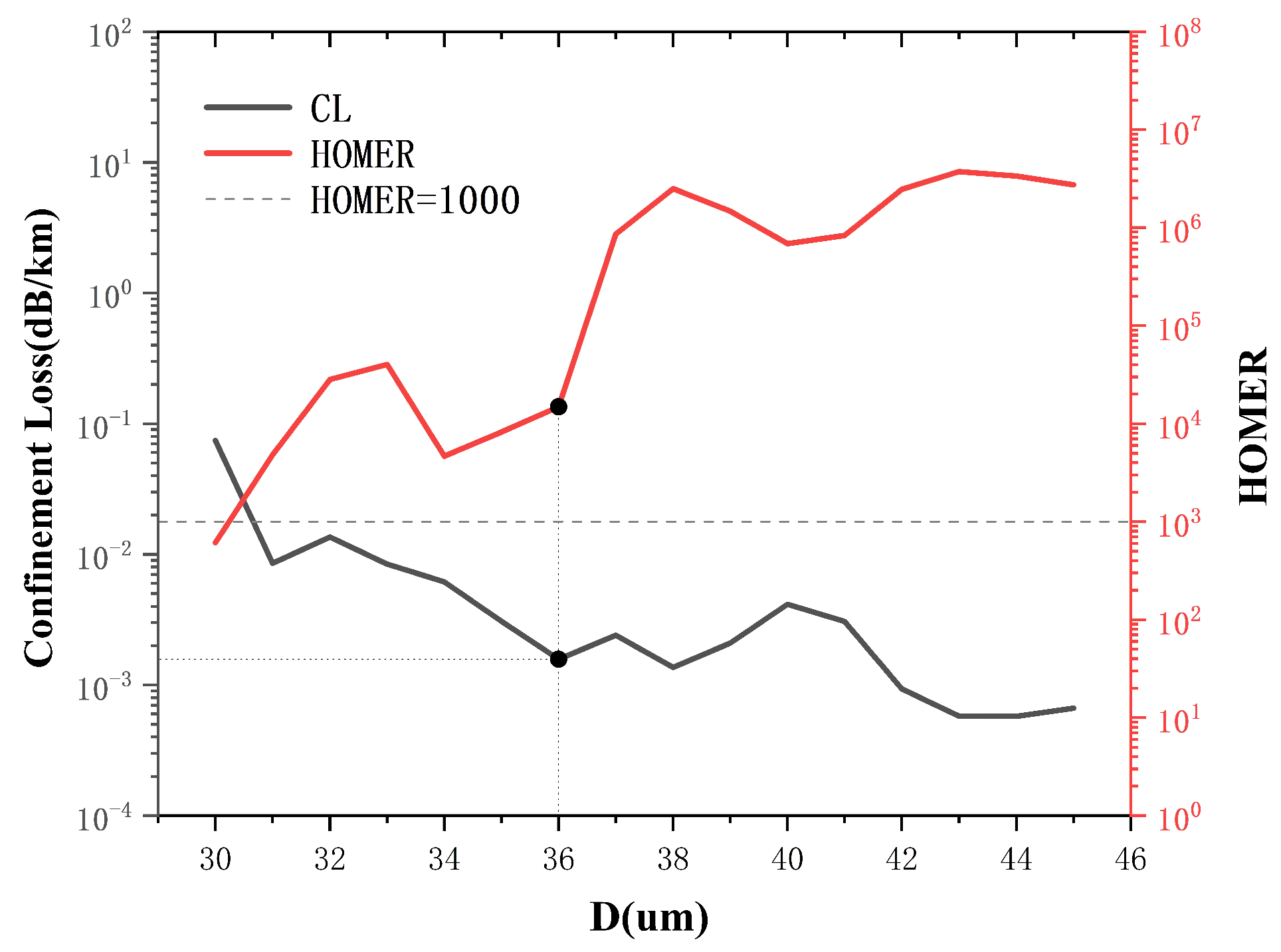
We observe that the CL for the fiber generally decreases with an increase in core diameter, whereas HOMER tends to increase, as deduced from the curves in
Figure 2. The gray dashed line in
Figure 2 indicates a HOMER value of 1000. It can be observed that when
D exceeds 30 μm, the fiber is likely to have excellent single-mode characteristics. Although increasing
D can improve the performance of the fiber, it also imposes several difficulties in real applications. We therefore select the position marked by the black dot as the core diameter, i.e.,
D = 36 μm. At this point, the fiber has both a low CL of 0.0015 dB/km and a high HOMER of 14,900, ensuring excellent loss characteristics and single-mode properties. Subsequent optimizations for this structure were carried out for
D = 36 μm,
t = 0.36 μm, and a wavelength of λ = 1.55 μm.
3.2. Parameters d1 and d2
After determining the size of the core, we then determined the other parameter values. The parameters of the elliptical tube element were set to
= 0.4 and
= 0.8 to minimize light leakage along the major axis of the elliptical tube. Based on these conditions, we conducted a parameter scan to determine the optimal values for
and
.
Figure 3a shows a pseudo-color plot of CL for varying values of
and
. The range of
is from 0.8 to 1.07, while the range of
is from 0.16 to 0.39. The blue area in
Figure 3a indicates that the CL of the fiber can be maintained at a relatively low level, as even the maximum CL value in the figure is below 0.1 dB/km. The minimum CL value of 0.00099 dB/km is located at the point where
= 0.91 and
= 0.33, as marked with a black triangle in
Figure 3a. This loss value is sufficiently small for application in long-distance fiber optic communication.
It is evident that changes in the value of
have a significant impact on CL. When
is less than 0.85 or greater than 1.05, CL gradually increases. The regions where the loss is greater than 0.01 dB/km are marked with white dashed lines.
Figure 3a(i–iv) to the right of
Figure 3a show the
mode field plots for the fiber in the corresponding areas, with the curves representing the intensity contours for the mode field. The increase in the loss in the region in
Figure 3a(i) is due to the large distance between adjacent resonant rings, which causes some light to leak through the gaps. In
Figure 3a(ii), a significant loss occurs because the size of the elliptical tube element is too large and the distance from the semi-circular tube is too small, generating cladding modes coupled from the fundamental mode. It is evident that the high loss observed in
Figure 3a(iii) can be attributed to the fact that, for this particular parameter, the effective refractive index of the modes supported by the air cavities in the cladding is analogous to that of the fundamental mode (
) in the core. This results in the coupling of the
mode into the cladding, leading to an elevated loss. The reason for the large loss in
Figure 3a(iv) is the small distance between two adjacent cladding structures. When two cladding structures are placed too closely, there is a tendency to generate new glass modes between them, thereby coupling fundamental mode light out of the core.
Figure 3b illustrates the variation in HOMER over the same parameter range as in
Figure 3a. In this figure, the regions within the grey dashed lines indicate HOMER values exceeding
, and when the value of
is around 0.95, the value of the HOMER can reach
or above. The maximum value of 3,615,358 is marked by a black triangle, and the corresponding mode field distribution is shown in
Figure 3b(vii). This indicates that the proposed optical fiber can achieve highly effective single-mode transmission.
The areas marked (v) and (vi) in
Figure 3b represent areas where the values of the HOMER are smaller than
. This can be attributed to a significant difference in the refractive indices between the modes in the cladding and the higher-order modes in the core; this means that the higher-order modes in the core are not well-coupled to the cladding, and adjustments to the cladding structure parameters are necessary to alter the cladding mode refractive index. The impact of the cladding structure size on the loss of higher-order modes is particularly evident with variation in the parameter
. When
is set to 0.95, the optical fiber consistently maintains a large HOMER. To the right of
Figure 3b, the areas marked (v)–(vii) represent
mode field patterns at corresponding positions of the optical fiber. By comparing (v) and (vi) with (vii), it is evident that the
mode at position (vii) is well-coupled to the cladding, leading to a significant loss of higher-order modes and ensuring a large HOMER value.
Figure 3a,b reveal that the point at which the minimum CL is obtained does not coincide with the point of maximum HOMER. Consequently, an alternative point of
= 0.95 and
= 0.33 is selected to balance the loss with the single-mode characteristic, giving a CL of 0.00146 dB/km and a HOMER of 283,056, representing excellent single-mode transmission with low loss.
3.3. Parameters a and b
Figure 4a depicts the variation in the CL as
ranges from 0.27 to 0.5 and
changes from 0.7 to 0.97. When
is less than 0.34, the distance between the semi-circular tube and the elliptical tube element increases, causing light leakage through the gap. The loss, therefore, becomes large, as seen in the high-loss region marked (i) in
Figure 4a. In contrast, when
exceeds 0.43, the distance between the semi-circular tube and the elliptical tube decreases and the size of the semi-circular tube increases. In this case, the fundamental mode in the core is prone to coupling to the cladding structure, leading to an increase in loss, as observed in region (ii) in
Figure 4a. The white circled area in the figure represents the area in which CL is below 0.01 dB/km. In addition, at values of
= 0.8 and
= 0.4, the minimum CL is 0.00146 dB/km, as marked by the black triangle.
Figure 4b presents a pseudo-color plot of the HOMER. The area enclosed by grey dashed lines represents the region where the HOMER exceeds
, indicating excellent single-mode transmission in the SSE-ARF. The maximum value for the HOMER in the figure is 1,694,239 and is marked by the black triangle. From
Figure 4b, it can be observed that the size of the elliptical structure has a significant impact on the single-mode characteristic of the fiber. To the right of
Figure 4b, by comparing (v) with (vi) and (vii), it can be observed that the
mode is well coupled to the cladding structure at the location of maximum HOMER.
In the same way as for the parameters and , the values of the parameters a and b corresponding to the minimum CL and the maximum HOMER are different. Ultimately, we chose numerical values of = 0.4 and = 0.8. At these parameter values, the CL for our SSE-ARF is 0.00146 dB/km, and the HOMER is 283,056. We believe that under these conditions, the SSE-ARF has good loss characteristics and single-mode characteristics in the communication wavelength range.
3.4. Summary and Discussion
In
Figure 5, the CL curves for the
and
modes and the HOMER curve for the SSE-ARF are plotted for values of
= 1.9 ×
D,
= 0.33 ×
,
a = 0.4 ×
, and
b = 0.8 ×
. The CL for the
mode is 0.00146 dB/km at a wavelength of 1.55 μm. The fluctuations in the fundamental mode CL curve are noticeable and can be attributed to the formation of nodes by the interconnection of cladding elements, leading to partial light leakage at these points. However, the SSE-ARF exhibits low losses (of below 0.1 dB/km) in the range 0.8–1.8 μm and below 0.01 dB/km in the range 1.02–1.7 μm, demonstrating excellent loss characteristics. On the right side of
Figure 5, the LP
01 mode field pattern is shown for a value of 1.55 μm, representing the effective confinement of light within the core. In addition, due to the loss fluctuations of the LP
01 mode and the absence of significant LP
11 mode loss fluctuations, the HOMER value for the SSE-ARF exhibits corresponding fluctuations with LP
01. At 1.55 μm, the value of the HOMER is 283,056, and this reaches a maximum at 1.42 μm with a value of 2,439,607. This implies that our SSE-ARF achieves single-mode transmission from the beginning of light propagation in the fiber. Hence, the SSE-ARF has an outstanding single-mode characteristic. In
Figure 5(ii), the high-order mode field pattern of the fiber at a wavelength of 1.55 μm is presented, showing effective coupling of light into the cladding.
The curves for CL against wavelength are plotted in
Figure 6a for four different fibers, where the orange, green, red, and blue lines represent 5-NANF [
42], 5-DNANF [
31], DT-DNANF [
32], and the proposed SSE-ARF, respectively. The parameters of each type of optical fiber correspond to their respective optimal parameter values.
Figure 6b shows the HOMER curves for the corresponding fibers. To the right of the figure, (i)–(iv) depict ideal cross-sectional views of the four fibers. As can be seen from
Figure 6a, the SSE-ARF can achieve a loss of less than 0.1 dB/km within the ultra-wide wavelength band from 0.8 to 1.8 μm. Moreover, the communication wavelength of 1.55 μm is marked with a black dot on the graph. It can be observed that near the communication wavelength, the SSE-ARF can obtain a relatively lowest loss value of 0.00033 dB/km, indicating that the SSE-ARF can achieve more excellent low-loss transmission performance. As can be seen from
Figure 6b, the SSE-ARF can achieve a relatively maximum HOMER value within the wavelength range of 1.2–1.55 μm, which means that it can achieve the most excellent single-mode transmission of the optical fiber.
4. Bending-Induced Loss
The bending sensitivity of SSE-ARF is another important characteristic. To explore this, we used a conformal mapping model, a widely used approach for calculating bending-induced loss in an optical fiber due to bending [
40,
43]. The principle of this model involves mapping the refractive index variation of the bent fiber against that of a straight fiber. The corresponding loss is then analyzed for a straight fiber. We set the bending direction as
x along the bending direction under the bending condition given by
where
x represents the distance from the core along the bending direction,
R is the bending radius, and
n is the refractive index of the material under straight fiber conditions. The bending-induced loss is calculated by subtracting the losses in the bent fiber from those in the straight fiber [
44,
45].
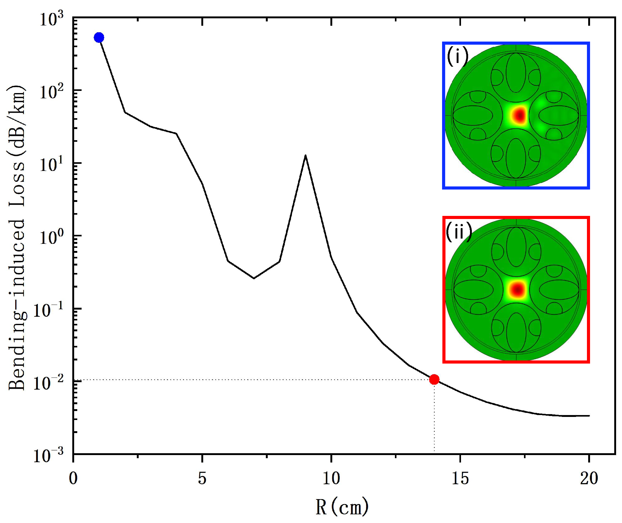
The curve in
Figure 7 illustrates the bending-induced loss as a function of the bending radius
R, ranging from 1 to 20 cm. From the loss variation curve, it can be observed that the bending-induced loss gradually decreases with an increase in the bending radius. As the fiber bends, the mode refractive index in the cladding will change; when this approaches (or matches) the fundamental mode refractive index in the core, the fundamental mode will be coupled to the cladding, resulting in significant losses. The peak loss at
R = 9 cm in
Figure 7, along with other loss points greater than this peak, is caused by the refractive index of the cladding mode approaching that of the
mode due to the bending of the optical fiber. This results in the coupling of the core mode into the cladding, leading to an increase in the loss of the
mode. The points at
R = 1 cm and
R = 14 cm are marked with blue and red dots, respectively.
Figure 7(i,ii) present the mode field profiles at these two points.
Figure 7(i) shows that even under extreme bending at 1 cm, the core can still confine most of the light, while
Figure 7(ii) reveals that at
R = 14 cm, the bending-induced loss is significantly reduced compared to
R = 1 cm, with a value of 0.015 dB/km. The loss drops below 0.01 dB/km for values of
R greater than 14 cm, indicating that bending-induced losses can be neglected beyond this point.
5. Fabrication Tolerance
In the actual process of preparing the optical fibers, it is difficult to precisely align the elliptical tube at a tangent to the jacked layer [
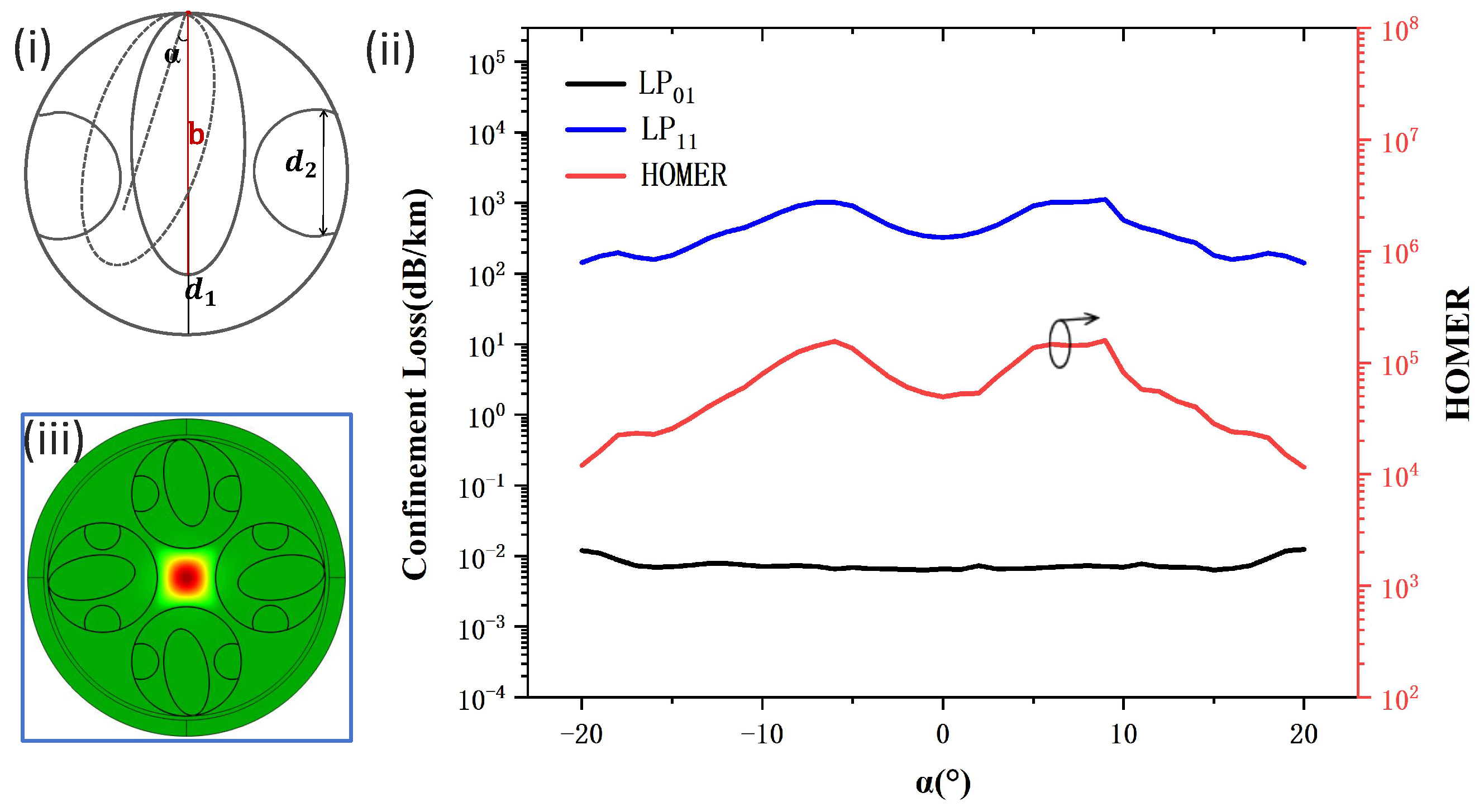
46], and the rotation angle of the elliptical tube element is therefore one of the main sources of fabrication error in optical fibers. We analyzed the impact of this manufacturing error on the performance of our SSE-ARF. In
Figure 8(i),
represents the angle between the axis of symmetry of the fiber cladding unit and the axis of symmetry of the long axis of the elliptical tube. When
> 0,
represents the angle by which the axis of symmetry of the long axis of the elliptical tube is offset to the right relative to the axis of symmetry of the cladding unit; when
< 0, the situation is the opposite. In our numerical study, the other parameters were set to the optimal performance values for SSE-ARF.
Figure 8(ii) shows the curves for the
and
modes, as well as the HOMER values for our SSE-ARF concerning the variation in
. It can be seen that the loss curve of the
mode does not change significantly with
. This is because, when the elliptical tube deviates within a certain range, the SSE-ARF can still maintain a stable suppression coupling model structure [
7], and the elliptical tube structure can still inhibit the leakage of the fundamental mode light in the core. In contrast, the
mode shows relatively significant fluctuations. This is because, when the elliptical tube element is moved, the shape and size of the air cavity in the cladding change, which alters the effective refractive index of the cladding mode. When the effective refractive index of the cladding mode approaches that of the
mode in the core, according to the suppression coupling model [
7], the
mode will couple with the cladding mode, thus leading to an increase in the loss of the
mode and ultimately causing a significant change in HOMER. From the HOMER curve, it can be seen that, when the elliptical tube element is rotated clockwise or counterclockwise by between 4° and 9°, the HOMER value is even larger than when the elliptical tube is tangent to the circular tube.
Figure 8(iii) represents the fundamental mode field pattern of the SSE-ARF for
= 10°, showing that the optical power is well confined within the core. Therefore, we can conclude that the performance of SSE-ARF is robust over a wide range of rotation of the elliptical tube element.
In general, the fabrication of an ARF consists of two main steps: fabrication of the preform, and drawing of the fiber [
31,
47]. However, the drawing process of an elliptical tube requires highly precise pressure management in the drawing tower, which has represented a long-standing challenge for conventional fiber manufacturing technology. As an alternative to the drawing process of an elliptical tube, the development of 3D printing technology offers another method for the fabrication of an ARF [
48]. In theory, 3D printing technology could be used to fabricate a fiber preform with complex geometries and low volumes. This opens up new opportunities for exploring very complex ARF designs that are impossible to fabricate using conventional fiber optic manufacturing techniques. Thus, the SSE-ARF has the potential to be successfully fabricated via 3D printing technology, which may bring revolutionary impacts on future fields such as optical fiber communication. Additionally, the specially optimized SSE-ARF also holds potential for applications in other domains like sensing and laser applications, warranting further exploration by researchers.

 ,
, 

