Abstract
A novel photonics-assisted technique for generating reconfigurable frequency hopping (FH) signals is proposed and demonstrated through optical comb filtering (OCF). The arithmetic progression of frequency difference between OCF passbands and optical frequency comb lines is exploited to enable wavelength selection controlled by an intermediate frequency signal, with ultra-wideband FH signals subsequently being generated through optical heterodyning. Comprehensive theoretical and numerical investigations are conducted, demonstrating the successful generation of diverse FH waveforms including 5-, 10-, and 25-level stepped frequency signals, Costas-coded patterns, as well as complex wideband signals such as 30 GHz linear frequency modulated and 24 GHz sinusoidal chirped waveforms. Critical system considerations including laser frequency stability, FH speed, and parameter optimization are examined. Wide tunable bandwidth exceeding 30 GHz, good stability, and inherent compatibility with photonic integration is achieved, showing significant potential for advanced applications in cognitive radio and modern radar systems where high-performance frequency-agile signal generation is required.
1. Introduction
The proliferation of wireless devices has exacerbated the scarcity of spectral resources. Consequently, modern radar and wireless communication systems require extensive, rapid, and flexible frequency tuning capabilities to mitigate frequency conflicts [1,2]. Additionally, the increasing demands for secure data transmission and anti-jamming have highlighted the growing importance of frequency hopping (FH) systems [3,4,5,6]. However, due to the inherent limitations in the operational bandwidth of electrical technologies, frequency hopping systems based on electrical frequency synthesis techniques face significant challenges in achieving real-time frequency hopping over a range of tens of gigahertz (GHz). Photonic-based technologies, characterized by their large operational bandwidth, low loss, immunity to electromagnetic interference, flexibility, reconfigurability, and potential for integration [7,8,9,10] have emerged as a promising alternative.
In recent years, various schemes for generating FH signals based on photonic technologies have been reported. In [11,12,13,14,15,16,17,18,19], FH signals with large frequency intervals and high hopping speeds are achieved through optical frequency switching, which is accomplished by adjusting the bias voltage of the Mach–Zehnder modulator (MZM) [11,12,13,14], the polarization direction in the polarization modulator (PolM) [15,16,17], and the passband of the optical filter [18,19]. Although these schemes realize wideband frequency hopping, the limited number of hopping points (typically two points) is insufficient to meet the flexibility requirements in practical scenarios. In [20], a four-level FH signal is generated by combining polarization direction control and bias control; however, further expansion of the FH points remains challenging. In [21,22], optical tunable filters based on micro-ring resonators (MRRs) or Mach–Zehnder interferometers (MZIs) are used to select the desired wavelengths of an optical frequency comb (OFC), thereby controlling the frequency of the output microwave signal. The FH frequency points in this method are determined by the number and spacing of the OFC comb lines, making it difficult to achieve flexible tuning to any arbitrary frequency within a given bandwidth. Additionally, increasing the number of FH points leads to greater complexity in the tunable optical filter, resulting in higher losses and reduced stability. In [23], a flexible FH generator based on dynamic control of an optically injected semiconductor is proposed. Despite this, the high spontaneous emission noise in the laser source results in poor frequency accuracy of the FH signals. In Reference [24], ultra-low phase noise FH signals are generated using a coupled optoelectronic oscillator (OEO). Nonetheless, the extended frequency switching times in the system limit the FH speed of the generated signals. In [25], the flexibility of the electrical frequency hopping and the large bandwidth of optical wavelength selection are integrated. Phase selection and wavelength switching on dual coherent OFCs control the frequency interval between the intermediate frequency FH signal’s optical sidebands and the optical local oscillator, enabling wideband and flexible FH signal generation. However, the use of optical switches restricts the FH speed.
In this work, a photonics-assisted FH signal generator based on OCF is proposed. By exploiting the arithmetic progression of frequency differences between OCF passbands and optical comb lines, wavelength selection is controlled via an intermediate frequency (IF) signal, enabling flexible FH signal generation through optical heterodyning. The proposed scheme offers three key advantages: (1) simultaneous wideband operation (30 GHz) and reconfigurable FH patterns; (2) passive wavelength selection without active tunable filters, improving stability and implementation feasibility; and (3) scalable operating bandwidth by adjusting the number of optical comb lines while maintaining the same system architecture. These features demonstrate the potential of this approach for advanced radar and cognitive radio applications requiring high-performance frequency-agile signal generation.
2. Theory and Principle
Figure 1a presents the architecture of the proposed photonic-aid flexible frequency hopping (FH) signal generator, which is composed of an optical frequency comb (OFC) generator, a band pass optical filter (OF), an optical comb filter (OCF), a pair of dual-parallel Mach–Zehnder modulators, a pair of 90° hybrids, and a photodetector (PD). Assume that the emitted optical signal of the OFC source can be expressed as follows:
where Ein, n, and FSR1 are the amplitude, index, and free spectrum range (FSR) of the OFC. f0 represents the frequency of the first wavelength of the optical frequency comb (OFC). The total number of OFC wavelengths is N. In the upper branch, the OFC is applied to DP-MZM1, and the carrier-suppressed right single-sideband (CS-RSSB) modulated by an intermediate frequency (IF) signal RF1 is provided by MSG1. The obtained signal can be obtained by the following equation:
where fRF1 is the frequency of the signal emitted from MSG1, and mDP1 is the modulation index of DP-MZM1. Jn(·) denotes the Bessel function of the first kind. The optical signal outputted by DP-MZM1 is then sent into the optical comb filter (OCF) to perform wavelength selection. The OCF is a narrow-band optical periodic filter with an FSR of FSR2. The central frequency of the n-th passband of the OCF is expressed as follows:
where f1 is the central frequency of the first passband of the OCF. Let Δf be the frequency difference between FSR1 and FSR2; then, (2) can be re-written as follows:
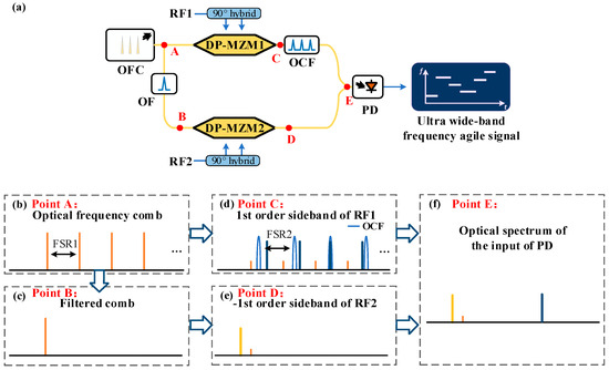
Figure 1.
(a) Schematic diagram of the proposed flexible frequency hopping signal generator. (b–f) The optical spectra at points A–E. OFC, optical frequency comb; OF, optical filter; DP-MZM, dual-parallel Mach–Zehnder modulator; OCF, optical comb filter; and PD, photodetector.
As shown in Figure 1d, by setting fRF1 to be (n − 1)Δf + f1 − f0, only the +1st order sideband of the n-th wavelength of the OFC falls in the passband of the OCF. Consequently, the filtered signal at the output of OCF is given by the following equation:
Therefore, the broadband wavelength selection controlled by an IF signal can be achieved. As illustrated in Figure 1c,e, the first wavelength extracted by the OF is the carrier-suppressed left single-sideband (CS-LSSB) modulated by the IF signal RF2 generated by MSG2 at DP-MZM2. The resultant signal can be expressed as follows:
where fRF2 is the frequency of the signal emitted from MSG2, and mDP2 is the modulation index of DP-MZM2. The optical signals EDP1(t) and EDP2(t) are combined and then sent into PD. After optical-to-electrical conversion, the photocurrent at the output of PD is given by the following equation:
As can be observed in (9), the frequency of iPD2(t) is defined by fRF1 and fRF2. By setting fRF1 to be (n − 1)Δf + f1 − f0, iPD2(t) is coarse converted to the frequency range of (fOCF − f0 + (l − 1)·FSR2, fOCF − f0 + l·FSR2). Tuning fRF2 from 0 to FSR2, a fine conversion can be achieved. Thus, by providing two IF FH signals from MSG1 and MSG2, the ultra-wideband flexible FH signal generation covering the frequency range of (fOCF − f0, fOCF − f0 + N·FSR2) can be achieved.
3. Simulation Results and Discussion
A simulation work based on the structure shown in Figure 1a was carried out using “Optisystem” to verify the theoretical analysis. The parameter settings are presented in Table 1. And the simulation setup is illustrated in Figure 2.

Table 1.
The parameter settings of the devices in the simulation.
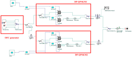
Figure 2.
The simulation setup of the proposed FH signal generator.
3.1. Optical Spectra Performance
The optical spectra of each device in the process of flexible FH signal generation are extracted and displayed in Figure 3. By setting the frequency of the first comb f0 and FSR1 to 191.1 THz and 5.8 GHz, a five-wavelength OFC is generated as shown in Figure 3a. For the OCF, f1 and FSR2 are set to be 191.1004 THz and 6 GHz, respectively. A 600 MHz single-tone signal generated by MSG1 is sent to DP-MZM1. The resultant spectrum is shown in Figure 3b. Due to the limited extinction ratio, the SSR of the generated signal is only 15.71 dB. Thanks to the narrow bandwidth of the OCF, only the +1st order sideband of the second wavelength can remain and the spurious component can be filtered out. As can be observed in zoomed spectra near the first, second, and third wavelengths presented in Figure 3c–e, the +1st order sideband near the second wavelength falls in the passband of the OCF. Thus, the wavelength selection is successfully implemented. On the other hand, another single-tone signal provided by MSG2 is applied to DP-MZM2, and the generated optical spectrum is shown in Figure 3f. Since the carrier cannot be well suppressed, an extra optical filter is utilized to extract the −1st order sideband. The filtered spectrum is given in Figure 3g. In Figure 3h, the output of OCF and OF2 are combined. After optical-to-electrical conversion, a wideband flexible FH signal can be obtained.
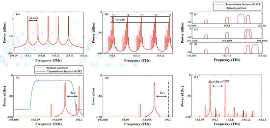
Figure 3.
The optical spectra at the output of (a) the OFC generator and (b) DP-MZM1. The zoomed optical spectra of DP-MZM1 near the (c) first, (d) second, and (e) third optical combs. The optical spectra at the output of DP-MZM2 (f) before and (g) after optical filtering. (h) The optical spectrum of the signal inputted to PD.
3.2. Demonstration of Wavelength Selection
To investigate the performance of wavelength selection, the driving RF signal provided by MSG1 is tuned from 0.4 GHz to 1.2 GHz with a step of 0.2 GHz as shown in Figure 4b. Controlled by the driving signals, the optical spectra of the selected wavelength are shown in Figure 4a. The wavelengths located at 193.1004 THz, 193.1064 THz, 193.1124 THz, 193.1184 THz, and 193.1244 THz are selected with an average SSR higher than 38 dB, indicating a high signal quality without interference of spurious components. Therefore, wavelength selection over a wide range of 30 GHz controlled by an IF signal under 1.2 GHz is achieved.
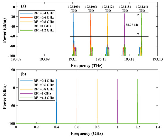
Figure 4.
(a) The optical spectrum of the selected wavelength and (b) the RF spectrum of the driving signal.
3.3. Demonstration of Flexible FH Signal Generation
In this study, the performance of FH signal generation is demonstrated. In this section, 5-level, 10-level, and 25-level stepped frequency signals with a period of 2.5 μs are generated. The frequency hopping intervals of the obtained signals are 6 GHz, 3 GHz, and 1.2 GHz. Based on the results of the Garbor transformation, the corresponding time–frequency diagrams are shown in Figure 5a–c. As can be observed, the FH signals exhibit concentrated energy at each frequency point, with no additional spurious frequency components present. In terms of the temporal waveforms of the generated signals shown in Figure 5d–f, slight periodic envelope fluctuations exist, particularly in Figure 5e,f. This is because the broadband optical bandpass filter OF2, used to suppress the optical carrier, has a non-flat passband response. Consequently, when the output signal frequency from MSG2 changes, the amplitude of the generated signal varies.
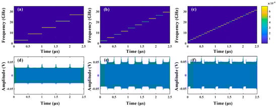
Figure 5.
The time–frequency diagram of the generated (a) 5-level, (b) 10-level, and (c) 25-level stepped frequency signals and their temporal waveforms (d–f).
In order to further investigate the flexibility of the proposed scheme, the generation of FH signals with random frequency order is implemented. Table 2 describes the parameter settings used to generate random FH signals. Here, we employ Costas sequences with lengths of 5, 10, and 25 to control the frequency order. The time–frequency diagrams of the generated signal are plotted in Figure 6a–c; the energy distributions are clear, consistent, and well with the theoretical analysis: 5, 10, and 25 frequencies with minimum frequency deviations of 6 GHz, 3 GHz, and 1.2 GHz exist in the diagrams and their frequency orders are in agreement with the ordering in Table 2. As can be found in the corresponding temporal waveforms in Figure 6d–f, the average amplitude is around 0.05 V. The fluctuations in the waveform envelope are within 20%.
Table 2.
Parameter settings for Costas FH signal generation.
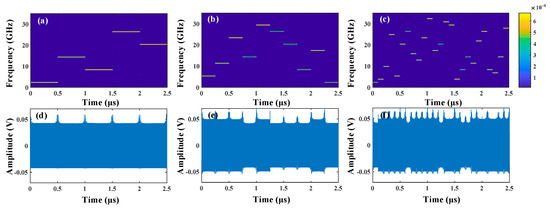
Figure 6.
(a–c) The time–frequency diagrams of the FH signals controlled by different Costas codes and (d–f) their temporal waveforms.
Moreover, the proposed scheme is capable of generating more complex frequency-agile signals with large bandwidths. As illustrated in Figure 7a, by incrementally increasing the output frequency of MSG1 from 0.4 GHz to 1.2 GHz in 0.2 GHz steps, and with MSG2 providing a 6 GHz bandwidth LFM signal, a wideband LFM signal with a bandwidth up to 30 GHz is successfully generated. In Figure 7b, a 24 GHz non-linearly chirped signal can also be obtained. The chirp shape of the signal is a smooth sinusoidal waveform with a period of 2.5 μs. The auto-correlation calculation results of the LFM signal and sinusoidal chirped signal are presented in Figure 7c,d, showing two sharp and narrow peaks. The full widths at half-maximum (FWHM) of the two peaks are 0.016 ns and 0.02 ns, respectively, corresponding to pulse compression ratios of 156,250 and 125,000, indicating excellent pulse compression performance. This suggests that the proposed scheme holds promising application prospects in high-resolution radar systems.
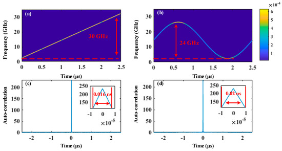
Figure 7.
Time–frequency diagrams of the generated (a) LFM signal and (b) sinusoidal chirped signal and their auto-correlation calculation results (c,d).
3.4. Effect of Frequency Offset Between OFC and OCF
In practice, non-ideal factors such as temperature variations and manufacturing limitations can lead to a time-varying frequency offset between the OFC and the passband of OCF, thereby affecting the quality of the generated FH signals. Setting the output frequency of MSG1 to be 0.4 GHz, then the +1 order sideband of the first wavelength of the OFC will theoretically be selected after the OCF. As shown in Figure 8(a-i), when there is no frequency offset, the desired sideband is precisely centered within the passband of the OCF. At this point, the filtered optical sideband exhibits maximum power, as illustrated in Figure 8(b-i), where the resulting spectrum achieves an SSR of 41.82 dB. When the OFC source has a 100 MHz frequency offset, as shown in Figure 8(a-ii), the desired optical sideband appears at the edge of the OCF passband, leading to a reduction in the power of the sideband in the OCF output signal. As seen in Figure 8(b-ii), the SSR of the output optical signal decreases to 9.08 dB. To further investigate the effect of frequency offset, frequency offset deviations are added to the simulation to monitor the SSR variation in the selected sideband. Figure 8c presents the recorded results. As evident from the plot, when the frequency offset is less than 40 MHz, the OSSR of the selected wavelength remains above 40 dB. If the offset exceeds 40 MHz, the OSSR drops significantly, falling below 10 dB at 100 MHz. This is due to the 100 MHz passband width of the OCF used in the simulation. When the frequency offset exceeds 40 MHz, the desired wavelength is positioned at the edge of the passband, resulting in a significant degradation of the OSSR of the generated signal. To mitigate the effects of frequency offset, a narrow-linewidth stable laser can be used to provide an OFC source with sufficiently low-frequency drift. Additionally, increasing the passband width of the OCF can enhance tolerance to frequency offsets. In this case, the frequency difference between FSR1 and FSR2 should be at least higher than the bandwidth of the passband of the OCF, BOCF. However, this approach may impact the frequency range of the generated signals and impose higher bandwidth requirements on the MSG. The required operating bandwidth of the RF source in practical applications and the maximum frequency range of the generated signals by the system will be investigated in the subsequent sections.
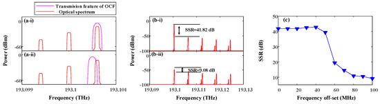
Figure 8.
(a-i) The zoomed optical spectra near the first wavelength without frequency offset and (a-ii) with a 100 MHz offset. (b-i) The optical spectra after the OCF without frequency offset and (b-ii) with a 100 MHz offset. (c) The SSR versus frequency offset curve of the filtered signal.
3.5. Analysis of FH Speed
For radar and spread spectrum communication applications, the FH speed is a critical parameter that determines the anti-interception performance of the systems. As for the proposed scheme, the FH speed is primarily determined by two factors: the hopping speed of the IF-FH signal generated by the MSG and the wavelength selection speed. The former is mainly constrained by the performance of the MSG, while the latter is related to the characteristics of the OCF. The maximum achievable FH speed of the system can be expressed as Fmax = min {FMSG, FWS}. Here, FMSG and FWS represent the maximum FH speeds of the MSG and wavelength selection, respectively.
As explained in the principle section, wavelength selection is achieved by filtering the desired optical sideband using the OCF. However, when the hopping speed increases, the spectrum of the IF-FH signal generated by the MSG will experience broadening. This broadening may extend into the passband of adjacent OCF channels, potentially causing crosstalk interference.
Let us define the frequency dwell time of the IF-FH signal output by MSG1 to be TFH; the FH speed of the proposed system is given as 1/TFH. Then, the IF-FH signal generated by MSG1 can be regarded as a superposition of sinusoidal pulses at different frequency points. Thus, within a short time period, the signal at a specific frequency point fFH can be expressed as follows:
where AFH is the amplitude and initial phase of this signal. Assume that the signal is SSB modulated to the OFC and one of the generated optical sidebands has the same central frequency as the n-th OCF passband. The time domain and frequency domain of this optical sideband are given by the following equations:
where mFH is the modulation index of DP-MZM1; rect(·) and sinc(·) denote rectangular window and sinc functions, respectively. Therefore, the null-to-null bandwidth of this optical sideband is Bnull = 2/TFH, which is directly proportional to the FH speed. The frequency difference between a selected optical sideband and the adjacent OCF passband is Δf − BOCF/2. Consequently, any spectral broadening of the optical sideband exceeding this value will leak into the neighboring channel, thereby degrading the spectral purity of the FH signal.
To investigate the performance of wavelength selection under different FH speeds, we set Δf and BOCF to be 200 MHnd 100 MHz, and the output frequency of MSG2 was set to 2 GHz. Meanwhile, the output signal of MSG1 is a frequency-stepped signal from 400 MHz to 1200 MHz with an interval of 200 MHz. By adjusting the FH speed to 10 MHz, 40 MHz, 80 MHz, and 160 MHz, the optical spectra around the OCF passband and the temporal waveforms and the time–frequency diagrams of the generated FH signals were determined. The results are presented in Figure 9. As shown in the optical spectra, higher FH speed leads to more severe spectral broadening of the optical sidebands. This broadening effect becomes particularly noticeable at an FH speed of 160 MHz, where we observe significant energy leakage from the main lobe beyond the OCF passband boundaries. While these spectral changes occur, the time domain waveform analysis reveals that the envelope characteristics remain largely unaffected by the varying FH speeds. As shown in the time–frequency diagrams in Figure 9(a-iii) to Figure 9(d-iii), when the FH speed is 10 MHz, the signal energy stays tightly concentrated in both time and frequency. But as the FH speed increases, the signal quality degrades noticeably. The energy starts scattering to other frequencies within each symbol period, creating interference between consecutive symbols. This inter-symbol interference (ISI) reaches its worst point at 160 MHz, where it becomes severe enough to potentially disrupt proper signal reception.
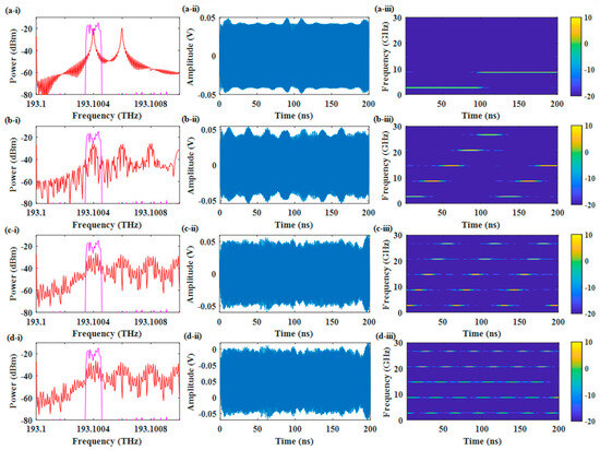
Figure 9.
(a-i–d-i) The optical spectra of the first passband of the OCF with FH speeds of 10 MHz, 40 MHz, 80 MHz, and 160 MHz (red) and the transmission feature of the OCF. (a-ii–d-ii) The temporal waveform of the FH signals with FH speeds of 10 MHz, 40 MHz, 80 MHz, and 160 MHz. (a-iii–d-iii) The time–frequency diagram of the FH signals with FH speeds of 10 MHz, 40 MHz, 80 MHz, and 160 MHz.
To quantitatively analyze the ISI characteristics under different frequency hopping speeds, Figure 10 presents the RF spectra during the first symbol period at various FH rates. The measured RFSSR (radio frequency sideband suppression ratio) demonstrates a clear degradation trend. At 10 MHz FH speed, the system achieves optimal performance with an RFSSR of 38.51 dB, indicating precise wavelength selection and minimal interference. This drops significantly to 24.33 dB at 40 MHz, 17.32 dB at 80 MHz, and deteriorates sharply to just 4.81 dB at 160 MHz. Figure 10b further illustrates this relationship through an averaged RFSSR-versus-FH-speed curve, obtained from five experimental trials. The curve clearly demonstrates the critical trade-off between FH speed and spectral purity; while higher speeds enable greater agility, they come at the cost of degraded signal integrity through increased ISI. This empirical relationship provides a quantitative framework to determine the maximum operable FH speed based on specific receiver requirements.
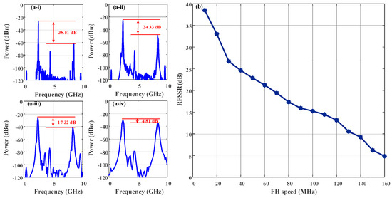
Figure 10.
(a-i–a-iv) The spectra of the FH signals with FH speeds of 10 MHz, 40 MHz, 80 MHz, and 160 MHz in the first symbol period. (b) The RFSSR vs FH speed curve.
3.6. Analysis of Maximum FH Bandwidth and Parameter Selection
In the simulation, the number of optical comb lines N of the OFC was set to 5, with the free FSRs of the OCF and OFC configured to 6 GHz and 5.8 GHz, respectively. Consequently, the FH signals generated are confined to a frequency range of 30 GHz. In practical applications, the maximum frequency hopping range can be expanded by increasing N, and it is also restricted by the values of FSR1 and FSR2.
According to the analysis in the principle section, the key to wavelength selection lies in matching the frequency of the IF signal output by the MSG with the frequency difference between the OFC comb lines and the center frequency of the OCF passband. Then, the frequency difference between the n-th OFC comb and the center frequency of the n-th OCF passband fd−n can be given as follows:
When fd−n exceeds FSR1, the frequency difference between the center frequency of the n-th passband and the frequency of the (n − 1)-th comb line, fd−n − FSR1, can cause crosstalk with another frequency difference fd−n′. This results in undesired wavelengths appearing within the passband. Figure 11 gives an example of an undesired wavelength selection results. Here, we set FSR1, FSR2, and f1 − f0 to be 5.6 GHz, 6 GHz, and 0.4 GHz. Mathematically, there is an ambiguity between fd−15-FSR1 and fd−1. As can be observed in Figure 8, when the output frequency of MSG1 is 0.4 GHz, both the +1st order sidebands of the first and 15th comb lines exist with high power. The SSR is only 5.42 dB. If we ignore the effect of the 15th comb line, the SSR is up to 39.97 dB.
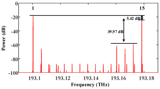
Figure 11.
The optical spectrum of the undesired wavelength selection result.
Thus, to ensure the effectiveness of wavelength selection, the maximum number of OFC comb lines N should satisfy the following:
As mentioned in the principle section, the frequency tuning range of the signals output by MSG2 should reach FSR2, meaning that the operational bandwidth of MSG2 should be at least FSR2. Under this premise, the maximum frequency tuning range Bmax of the proposed generator can be expressed as follows:
In practical engineering applications, the signal generation system frequently does not necessitate a frequency tuning range as extensive as Bmax. Consequently, the number of OFC comb lines N can be chosen according to the specific requirements. Correspondingly, the operational bandwidth of MSG1 should be broader than N·Δf. To achieve lower costs, it is generally desirable to minimize the real-time operating bandwidth requirements of the RF signal source for the system. This implies that, while ensuring the operating frequency range of the flexible FH signal generator meets the requirements, both FSR2 and N·Δf should be minimized. However, a smaller FSR for the OCF increases the fabrication complexity and cost. Additionally, the value of Δf must also meet the system’s tolerance requirements for laser source frequency offset. Therefore, the selection of various parameters for the proposed scheme can be described by the following optimization problem:
In this optimization problem, the objective is to minimize both FSR2 and N·Δf to achieve lower costs and simpler fabrication. The constraints ensure the following:
- FSR2 is not smaller than the minimum feasible FSR, FSRmanu, considering fabrication complexity and cost.
- N is at most Nmax, which is the maximum number of comb lines for effective wavelength selection.
- N·FSR2 meets the required frequency tuning range B.
- Δf is at least fprotect. fprotect must ensure robustness against laser frequency offset while meeting the frequency hopping rate requirements.
3.7. Comparison with the Related Work
Based on the analysis above, the comparison of this work with other reported multi-level FH signal generation schemes is shown in Table 3. Hopping level, operational bandwidth, frequency tunability, and limitations are evaluated and summarized. Thanks to the periodic characteristics of OFC and OCF, the operational bandwidth of the proposed generator can be easily extended to tens of GHz. Simultaneously, with the precise combination of electrical frequency hopping signal generation, it exhibits flexible frequency tuning performance and good frequency accuracy. Noteworthy, the proposed scheme adopts OCF as a passive element, which demonstrates superior stability compared to tunable filters. Furthermore, the absence of optical switch components eliminates the introduction of additional frequency switching time. The design does not require the use of long optical fiber loops, thereby presenting a more promising prospect for integration. This characteristic facilitates a reduction in both volume and power consumption while simultaneously improving stability. Although the current study lacks experimental validation, we confirm the experimental feasibility of all critical components in our design. The OFC can be implemented using external modulation techniques [26,27], high-Q microresonators [28], or mode-locking technology [29], with the mode-locking approach providing superior frequency stability. The OCF can be realized through multiple approaches, including the Mach–Zehnder interferometer [30], temperature-insensitive multi-mode interference waveguides [31], and Fabry–Pérot (FP) etalons. More advanced implementations may utilize cascaded differential-group-delay elements to achieve tunable optical comb filtering with adjustable bandwidth and FSR [32].
Table 3.
The comparison of several photonic multi-level FH signal generation schemes.
4. Conclusions
In this study, a photonic-aid flexible FH signal generator based on optical comb filtering was proposed and investigated. In the simulation work, 5-level, 10-level, and 25-level stepped and Costas sequence-controlled FH signals were obtained. The frequency hopping bandwidth and hopping rate achieved 30 GHz and 0.1 GHz, respectively. The generation of more complex frequency-agile signals including a 30 GHz LFM signal and a 24 GHz sinusoidal chirped signal were achieved. Moreover, it was determined that the frequency hopping bandwidth can be extended by increasing the number of optical comb lines in the OFC. The effects of laser frequency offset and the selection of system parameters were analyzed. Methods to minimize the bandwidth requirements of the RF signal source, while still satisfying application demands, were presented. The proposed scheme, offering a wide operational bandwidth, flexible frequency tuning performance, good stability, and promising integration potential, is expected to find applications in cognitive radio and modern radar systems.
Author Contributions
Supervision, X.L. and S.Z.; writing—original draft preparation, Y.Z.; writing—review and editing, X.L., G.W., R.W., J.M. and Z.Z. All authors have read and agreed to the published version of the manuscript.
Funding
This research received no external funding.
Institutional Review Board Statement
Not applicable.
Informed Consent Statement
Not applicable.
Data Availability Statement
Data are contained within the article.
Conflicts of Interest
The authors declare no conflicts of interest.
References
- Ghelfi, P.; Laghezza, F.; Scotti, F.; Serafino, G.; Capria, A.; Pinna, S.; Onori, D.; Porzi, C.; Scaffardi, M.; Malacarne, A.; et al. A Fully Photonics-Based Coherent Radar System. Nature 2014, 507, 341–345. [Google Scholar] [CrossRef]
- Romashov, V.V.; Romashova, L.V.; Khramov, K.K.; Yakimenko, K.A.; Doktorov, A.N. Wide-Band Hybrid Frequency Synthesizer with Improved Noise Performance. In Proceedings of the 2018 Moscow Workshop on Electronic and Networking Technologies (MWENT), Moscow, Russia, 15–18 May 2018; pp. 1–4. [Google Scholar]
- Chen, R.; Li, Z.; Shi, J.; Guan, L.; Zhang, J. High Secure Sequence Design in Frequency Hopping Communications. China Commun. 2019, 16, 139–150. [Google Scholar]
- Skolnik, M. Radar Handbook; McGraw-Hill: New York, NY, USA, 2008. [Google Scholar]
- Simon, M.K.; Omura, J.K.; Scholtz, R.A.; Levitt, B.K. Spread Spectrum Communications Handbook; McGraw-Hill: New York, NY, USA, 1994. [Google Scholar]
- Neri, F. Introduction to Electronic Defense Systems, 3rd ed.; Artech: Norwood, MA, USA, 2018. [Google Scholar]
- Liu, Q.; Fok, M.P. Ultrafast and Wideband Microwave Photonic Frequency-Hopping Systems: A Review. Appl. Sci. 2020, 10, 521–538. [Google Scholar] [CrossRef]
- Kumar, N.; Suthar, B. Advances in Photonic Crystals and Devices; CRC Press: Boca Raton, FL, USA, 2019. [Google Scholar]
- Singh, A.; Thapa, K.B.; Kumar, N. Analysis and design of optical biosensors using one-dimensional photonic crystals. Optik 2015, 126, 244–250. [Google Scholar] [CrossRef]
- Kumar, N.; Saraf, J. Tunable reflectance characteristics of magnetized cold plasma-based one-dimensional defective photonic crystal. Optik 2022, 252, 168577. [Google Scholar] [CrossRef]
- Feng, X.; Yan, L.; Li, P.; Ye, J.; Zou, X.; Pan, W.; Luo, B. Photonic Approach for Generation and Fast Switching of Binary Digitally Modulated RF Signals. IEEE Photonics J. 2020, 12, 1–8. [Google Scholar] [CrossRef]
- Lei, M.; Zheng, Z.; Song, C.; Bai, Y.; Qian, J.; Huang, S.; Gao, X. Equivalent Photonic Switch for Microwave Frequency Shift Keying Signal Generation. Opt. Lett. 2019, 44, 3138–3141. [Google Scholar] [CrossRef]
- Chen, Y. High-Speed and Wideband Frequency-Hopping Microwave Signal Generation via Switching the Bias Point of an Optical Modulator. IEEE Photonics J. 2018, 10, 1–7. [Google Scholar] [CrossRef]
- Cao, P.; Hu, X.; Zhang, L.; Wu, J.; Jiang, X.; Su, Y. Photonic Generation of Microwave Frequency Shift Keying Signal Using a Single-Drive Mach-Zehnder Modulator. Opt. Express 2014, 22, 14433. [Google Scholar] [CrossRef]
- Huang, L.; Wang, P.; Xiang, P.; Chen, D.; Zhang, Y.; Tao, J.; Pu, T.; Chen, X. Photonic Generation of Microwave Frequency Shift Keying Signals. IEEE Photonics Technol. Lett. 2016, 28, 1928–1931. [Google Scholar] [CrossRef]
- Li, X.; Zhao, S.; Zhang, K.; Zhu, Z.; Zheng, Y.; Liang, D. Photonic Generation of Microwave Binary Digital Modulation Signal with Format Agility and Parameter Tunability. Opt. Commun. 2018, 429, 106–111. [Google Scholar] [CrossRef]
- Ye, J.; Yan, L.; Wang, H.; Pan, W.; Luo, B.; Zou, X. Photonic Generation of Microwave Frequency Shift Keying Signal Using a Polarization Maintaining FBG. IEEE Photonics J. 2018, 10, 1–8. [Google Scholar] [CrossRef]
- Xie, Y.; Zhuang, L.; Jiao, P.; Dai, D. Sub-Nanosecond-Speed Frequency Reconfigurable Photonic Radio Frequency Switch Using a Silicon Modulator. Photonics Res. 2020, 8, 852–857. [Google Scholar] [CrossRef]
- Jiang, H.; Yan, L.; Pan, Y.; Pan, W.; Luo, B.; Zou, X.; Eggleton, B. Microwave Photonic Comb Filter with Ultra-Fast Tunability. Opt. Lett. 2015, 40, 4895–4898. [Google Scholar] [CrossRef]
- Feng, X.; Yan, L.; Jiang, H.; Li, P.; Ye, J.; Zhou, Y.; Pan, W.; Luo, B.; Zou, X.; Zhou, T. Photonic Generation of Multilevel Frequency-Hopping Microwave Signal. IEEE Photonics J. 2019, 11, 1–7. [Google Scholar] [CrossRef]
- Zhou, F.; Wang, X.; Yan, S.; Hu, X.; Zhang, Y.; Qiu, H.; Xiao, X.; Dong, J.; Zhang, X. Frequency-Hopping Microwave Generation with a Large Time-Bandwidth Product. IEEE Photonics J. 2018, 10, 1–9. [Google Scholar] [CrossRef]
- Wang, G.; Meng, Q.; Li, Y.; Li, X.; Zhou, Y.; Zhu, Z.; Gao, C.; Li, H.; Jiang, W.; Zhao, S. High-Speed and Wideband Multilevel Frequency-Hopping Microwave Signal Generation Based on a Sagnac Loop. Results Phys. 2023, 52, 106807. [Google Scholar] [CrossRef]
- Zhou, P.; Zhang, F.; Ye, X.; Guo, Q.; Pan, S. Flexible Frequency-Hopping Microwave Generation by Dynamic Control of Optically Injected Semiconductor Laser. IEEE Photonics J. 2016, 8, 1–9. [Google Scholar] [CrossRef]
- Liu, H.; Guo, M.; Zhang, T.; Dai, J.; Xu, K. Ultralow-Phase-Noise and Broadband Frequency-Hopping Coupled Optoelectronic Oscillator Under Quiet Point Operation. Photonics Res. 2024, 12, 1785–1793. [Google Scholar] [CrossRef]
- Bochao, K.; Li, L.; Qinggui, T.; Zan, L.; Jinman, G.; Zhongbo, Z.; Xiaojun, L.; Xiongfei, L. Wideband Microwave Frequency-Hopping Signal Generation Technology Based on Coherent Double Optical Comb. J. Light. Technol. 2024, 42, 7634–7642. [Google Scholar] [CrossRef]
- He, C.; Pan, S.; Guo, R.; Zhao, Y.; Pan, M. Ultraflat optical frequency comb generated based on cascaded polarization modulators. Opt. Lett. 2012, 37, 3834–3836. [Google Scholar] [CrossRef] [PubMed][Green Version]
- Wei, R.; Yan, J.; Peng, Y.; Yao, X.; Bai, M.; Zheng, Z. Optical frequency comb generation based on electro-optical modulation with high-order harmonic of a sine RF signal. Opt. Commun. 2013, 291, 269–273. [Google Scholar] [CrossRef]
- Del’Haye, P.; Schliesser, A.; Arcizet, O.; Wilken, T.; Holzwarth, R.; Kippenberg, T.J. Optical frequency comb generation from a monolithic microresonator. Nature 2007, 450, 1214–1217. [Google Scholar] [CrossRef] [PubMed]
- Fukuchi, Y.; Miyauchi, R. Optical Frequency Comb Generation from a Bismuth-Based Mode-Locked Fiber Laser. In Proceedings of the 2022 Asia Communications and Photonics Conference (ACP), Shenzhen, China, 5–8 November 2022; pp. 308–311. [Google Scholar]
- Kumar, A.; Raghuwanshi, S.K.; Kumar, S. Analysis of the tunable optical comb filter by using Mach-Zehnder interferometer. In Proceedings of the 2013 6th IEEE/International Conference on Advanced Infocomm Technology (ICAIT), Taipei, Taiwan, 6–9 December 2013; pp. 179–181. [Google Scholar]
- Lee, Y.L.; Choi, Y.W.; Jung, H.S.; Eom, T.J.; Shin, W.; Ko, D.K.; Yang, W.S.; Lee, H.M.; Kim, W.K.; Lee, H.Y. Temperature-Insensitive Dual-Comb Filter Based on Multimode Interference Ti:LiNbO3 Waveguide. IEEE Photonics Technol. Lett. 2009, 21, 507–509. [Google Scholar] [CrossRef]
- Yan, L.S.; Ye, J.; Jiang, H.Y.; Pan, W.; Luo, B.; Yi, A.L.; Guo, Y.H.; Yao, X.S. A Photonic Comb Filter with Independently and Digitally Tunable Bandwidth and Frequency Spacing. IEEE Photonics Technol. Lett. 2011, 23, 857–859. [Google Scholar] [CrossRef]
Disclaimer/Publisher’s Note: The statements, opinions and data contained in all publications are solely those of the individual author(s) and contributor(s) and not of MDPI and/or the editor(s). MDPI and/or the editor(s) disclaim responsibility for any injury to people or property resulting from any ideas, methods, instructions or products referred to in the content. |
© 2025 by the authors. Licensee MDPI, Basel, Switzerland. This article is an open access article distributed under the terms and conditions of the Creative Commons Attribution (CC BY) license (https://creativecommons.org/licenses/by/4.0/).