Article

On the Performance of Non-Lambertian Relay-Assisted 6G Visible Light Communication Applications

1
College of Technology and Data, Yantai Nanshan University, Yantai 265713, China
2
Key Laboratory of Signal Detection and Processing in Xinjiang Uygur Autonomous Region, School of Computer Science and Technology (School of Cyberspace Security), Xinjiang University, Urumqi 830046, China
3
China Mobile Research Institute, Beijing 100053, China
4
Department of Electronic Engineering, Beijing National Research Center for Information Science and Technology, Tsinghua University, Beijing 100084, China
*
Author to whom correspondence should be addressed.
Photonics 2025, 12(6), 541; https://doi.org/10.3390/photonics12060541
Submission received: 31 March 2025 / Revised: 9 May 2025 / Accepted: 23 May 2025 / Published: 26 May 2025

Abstract

:
Visible light communication (VLC) has become one important candidate technology for beyond 5G and even 6G wireless networks, mainly thanks to its abundant unregulated light spectrum resource and the ubiquitous deployment of light-emitting diodes (LED)-based illumination infrastructures. Due to the high directivity of VLC channel propagation, relay-based cooperative techniques have been introduced and explored to enhance the transmission performance of VLC links. Nevertheless, almost all current works are limited to scenarios adopting well-known Lambertian transmitter and relay, which fail to characterize the scenarios with distinctive non-Lambertian transmitter or relay. For filling this gap, in this article, relay-assisted VLC employing diverse non-Lambertian optical beam configurations is proposed. Unlike the conventional Lambertian transmitter and relay-based research paradigm, the presented scheme employs the commercially available non-Lambertian transmitter and relay to configure the cooperative VLC links. Numerical results illustrate that up to 40.63 dB SNR could be provided by the proposed non-Lambertian relay-assisted VLC scheme, compared with about a 34.22 dB signal-to-noise ratio (SNR) of the benchmark Lambertian configuration.

1. Introduction

To address the exponentially increasing demands on data throughput, visible light communication (VLC) is becoming one promising enabling technique beyond 5G and future 6G wireless networks [1,2,3,4,5]. Compared to the conventional radio frequency (RF)-based technology, VLC is capable of offering several advantages, including license-free and abundant optical spectrum resource, low-cost light front end, natural immunity to the RF electromagnetic interference, provision of illumination function, and superior security performance [6,7,8,9,10]. On the other side, due to the high directivity of VLC signal propagation, the limited coverage footprint and the unsatisfying link reliability are viewed as the bottleneck issues that seriously hinder VLC commercialization [11,12,13,14,15]. To derive broader coverage and improved mobility, a variety of relay and cooperative communication techniques are introduced to VLC system designs [16,17,18,19].
In particular, the authors in [8] investigated how a relay technique could improve the error rate performance of one typical optical orthogonal frequency division multiplexing (OFDM) VLC system, and the optimum allocation of available light-emitting diode (LED) chips between the ambient light source, i.e., the source terminal and the task light, i.e., relay terminal, was determined. Moreover, the study in [9] presented one simulation model for a VLC channel with amplify-and-forward (AF) relay and showed that even in scenarios with low power and signal-to-noise ratio (SNR), the cooperation relay is capable of improving the VLC system performance. Similarly, the authors in [10] proposed a decode-and-forward (DF) relay-aided VLC system with non-orthogonal multiple access (NOMA) to improve the system outage performance of the cell-edge users. In addition, the work in [11] studied the outage and symbol error performance of this hybrid VLC-RF system with spatially random terminals under DF and AF schemes, respectively. Accordingly, approximated analytical and asymptotic expressions for the outage probability of the considered system were derived as well. Similarly, the work in [12] studied the outage performance of a cooperative hybrid VLC-RF wireless sensor network (WSN) under DF and AF relay schemes, respectively. At the same time, the authors in [13] focused on an efficient repeater-assisted VLC to address this efficient uplink transmission, and verified that the installation of the repeaters enhances the performance significantly with reduced size and power requirement of LEDs. In novel spatial modulation (SM) format aspect, the authors in [14] proposed an indoor cooperative incremental hybrid decode-amplify-forward (IHDAF) protocol-based SM VLC system to resist the channel propagation fading and improve the system performance. More recently, one novel wireless backhaul solution was proposed for indoor optical attocell networks in [16], which adopts the multi-hop relay wireless optical links to connect base stations (BSs) and the gateway. In addition, the cascaded channel analysis was accomplished for an indoor VLC relay-assisted system, in which the relay also received part of the reflected signal from the main source [17]. In physical layer security (PLS) aspects, a novel joint relay–jammer selection algorithm was proposed in [18] to enhance the secrecy performance of the hybrid RF/VLC system with multiple DF relaying nodes. With regard to outdoor application scenarios, the authors in [19] investigated a vehicle-to-vehicle relay-assisted VLC link and analyzed the effect of the relay vehicle’s orientation with respect to the source vehicle.
Nevertheless, almost all of these relay-assisted VLC works assume that the concerned LED-based transmitter and relay follow the conventional Lambertian optical beam pattern, which objectively ignores the potential beam diversity and the relevant design degree of freedom. As a matter of fact, the fundamental measurement and modeling works have illustrated that the distinct non-Lambertian optical beam patterns could be elaborately designed and manufactured by the international LED producers [20,21]. Additionally, the non-Lambertian optical beam patterns have been introduced and discussed in many research branches of the VLC domain, including, but not limited to, channel modeling and characterization [22,23], cells planning, access points design, coordinated coverage, multiple input multiple output, multiple optical beam switching, and secure optical wireless links [24,25]. And the optical beam effect and the potential performance are estimated and illustrated in respective VLC branch directions.
However, up to now, to the best of our knowledge, the distinctive non-Lambertian optical beams, the potential available beam configurations, and the respective performance characteristics are still waiting for fundamental investigation and numerical evaluation in the relay-assisted VLC research branch. Motivated by the observations above, in this paper, the typical non-Lambertian beams are employed to construct the relay-assisted VLC transmission links. As one of the first pioneering studies investigating relay-assisted visible light communications based on the ubiquitous non-Lambertian illumination infrastructure, this work overcomes the limitation of the conventional studies of the relay-assisted visible light communications, which fail to consider the optical beam diversity of the actual and ubiquitous LED illumination infrastructure as the lack of capability to simultaneously satisfy the professional need of communications, optics, radiometry, and illumination. To address the quite challenging interdisciplinary research, for the first time, this work successfully contributes towards providing the complete analytic system architecture of non-Lambertian relay-assisted visible light communications for the potential readers, and illustrates the exciting design dimension for the relay-assisted visible light communications. Objectively, this work provides abundant research opportunities for the researcher in the direction of relay-assisted visible light communications.
In this paper, the amplify-and-forward (AF) relay-assisted VLC employing diverse optical beam configurations are presented in Section 2. Numerical evaluation is presented in Section 3. Finally, Section 4 concludes this paper.

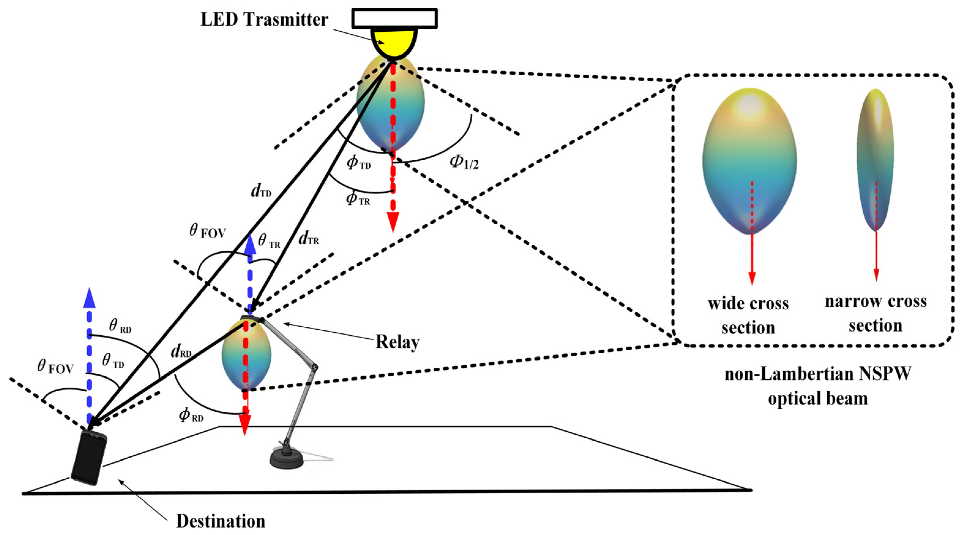
2. Relay-Assisted VLC Employing Diverse Optical Beam Configurations

To a large extent, the relay-assisted VLC channel gain and coverage characteristic are dominated by the optical beam pattern of LED source in the concerned transmitters. In actuality, the distinct beam patterns objectively provide one novel design and exploration dimension for relay-assisted VLC performance enhancement.

2.1. Relay-Assisted VLC Employing Benchmark Lambertian Beam Configurations

According to the classic photometry theory, radiation intensity is usually adopted as one key metric to measure the spatial radiation characteristics of optical beam configurations. Typically, when the LED optical source matches with benchmark Lambertian beam configurations, the response radiation intensity can be calculated by the following [20,22]:
I Lam ϕ = m Lam + 1 2 π cos m Lam ϕ ,
where ϕ is the angle of emission, and m Lam is the Lambertian order.
In typical relay-assisted indoor VLC scenario, the proportion of non-line-of-sight paths component is much less than the counterpart of line-of-sight (LOS) path. To simplify the analysis, this article only considers the contribution of the LOS path. Therefore, when the radiation characteristic of the optical source follows the benchmark Lambertian beam, the channel gain from the Lambertian source S Lam to the receiver, i.e., destination D, could be given as follows [20,22]:
H TD ( S Lam , D ) = A R d TD 2 I Lam ϕ TD cos θ TD n 2 sin 2 θ FOVD ,     0 θ TD θ FOVD 0 , θ TD > θ FOVD = A R m Lam + 1 2 π d TD 2 cos m Lam ϕ TD cos θ TD n 2 sin 2 θ FOVD , 0 θ TD θ FOVD 0 , θ TD > θ FOVD
where A R is the detection area of destination; d TD denotes the LOS distance between the optical source and the destination; ϕ TD is the angle of emission from the optical source to the destination; θ TD denotes the angle of incidence from the optical source to the destination; n denotes the refractive index of the optical concentrator; and θ FOVD is the field of view (FOV) of the destination receiver. When the Lambertian order is set as 1, then the respective 3D radiation pattern is illustrated in Figure 1, and in Figure 1, one indoor 6G IoT scenario with relay-assisted VLC employing benchmark Lambertian beams is illustrated. The electrical signal received by the destination receiver in the first phase of the relay-assisted VLC downlink transmission could be given as follows:
r TD Lam t = ρ T η D H TD ( S Lam , D ) x T t + w TD t ,
where ρ T denotes the electrical to optical coefficient of the optical source, η D denotes the photodetector response of the destination receiver, x T t is the unipolar time domain waveform signal in the electrical domain, and w TD t is the additive white Gaussian noise (AWGN) of the LOS link from the optical source to the destination. And, specifically, the unipolar waveform signal x T t could be expressed as follows:
x T t = P elec x t + B T ,
where P elec denotes the total electrical signal power for transmission, x t denotes the original bipolar signal in electrical domain, and B T is one added direct current (DC) bias component for transforming the original bipolar signal into the unique one. And the effective received signal-to-noise ratio (SNR) in the first phase of the AF relay-assisted VLC transmission could be denoted as
S N R TD Lam = ρ T 2 η D 2 H TD 2 ( S Lam , D ) P elec σ TD 2
where σ TD 2 denotes the total variance of the AWGN w TD t at the destination. Accordingly, this total noise could be given by the sum of the main noise components:
σ TD 2 = σ shot 2 + σ thermal 2 ,
where σ shot 2 denotes the shot noise variance at the receiver destination, and σ thermal 2 denotes the thermal noise variance at the receiver destination. In the first phase of the AF relay-assisted VLC transmission, the received VLC signal at the intermediate relay node could be represented as
r TR Lam t = ρ T η R H TR ( S Lam , R ) x T t B T + w TR t ,
where η R denotes the photodetector responsivity of the AF relay R , H TR ( S Lam , R ) denotes the channel gain from the Lambertian source S Lam to the AF relay R , and w TR t is the additive white Gaussian noise (AWGN) of the LOS link from the optical source to the intermediate relay node. Similarly, when the LED radiation characteristic of the relay node also follows the benchmark Lambertian beam, the channel gain from the Lambertian source S Lam to the relay R could be given as follows:
H TR ( S Lam , R ) = A R d TR 2 I Lam ϕ TR cos θ TR n 2 sin 2 θ FOVR ,     0 θ TR θ FOVR 0 , θ TR > θ FOVR                                     = A R m Lam + 1 2 π d TR 2 cos m Lam ϕ TR cos θ TR n 2 sin 2 θ FOVR , 0 θ TR θ FOVR 0 , θ TR > θ FOVR ,
where d TR denotes the LOS distance between the optical source and the intermediate relay node; ϕ TR is the angle of emission from the optical source to the relay node; θ TD denotes the angle of incidence from the optical source to the relay node; and θ FOVR is the field of view (FOV) of the relay receiver. As the AF VLC Lambertian relay could directly amplify the received signal r TR Lam t in the electrical domain by one amplification factor λ , the transmitted signal by the Lambertian relay node could be given by the following:
x R Lam t = λ r TR Lam t + B R ,
where B R denotes the DC biasing level of the Lambertian relay node. In the second phase of the relay-assisted VLC downlink transmission, the destination node will receive the signal from the AF VLC Lambertian relay node r TRD Lam t , which could be described as follows [8,9]:
r TRD Lam t = ρ R η D H RD ( R Lam , D ) x R Lam t + w RD t                           = ρ R η D H RD ( R Lam , D ) λ r TR Lam t + B R + w RD t                           = ρ R η D H RD ( R Lam , D ) λ ρ T η R H TR ( S Lam , R ) x T t B T + w TR t + B R + w RD t                           = ρ R η D H RD ( R Lam , D ) λ ρ T η R H TR ( S Lam , R ) P elec x t + w TR t + B R + w RD t ,
where H RD ( R Lam , D ) denotes the channel gain from the AF Lambertian relay R Lam to the destination node, and w RD t is the AWGN of the LOS link from the intermediate VLC relay node to the VLC destination node. Similarly, the channel gain H RD ( R Lam , D ) could be described as follows:
H RD ( R Lam , D ) = A R d RD 2 I Lam ϕ RD cos θ RD n 2 sin 2 θ FOVD ,     0 θ RD θ FOVD 0 , θ RD > θ FOVD                 = A R m Lam + 1 2 π d RD 2 cos m Lam ϕ RD cos θ RD n 2 sin 2 θ FOVD , 0 θ RD θ FOVD 0 , θ RD > θ FOVD ,
where d RD denotes the LOS distance between the relay and the destination node; ϕ RD is the angle of emission from the relay node to the destination node; and θ RD denotes the angle of incidence from the relay node to the destination node. And the effective received SNR in the second phase of the AF Lambertian relay-assisted Lambertian VLC transmission could be denoted as follows [8,9]:
S N R TRD Lam = ρ T 2 η R 2 ρ R 2 η D 2 H TR 2 ( S Lam , R ) H RD 2 ( R Lam , D ) λ 2 P elec ρ R 2 η D 2 H RD 2 ( R Lam , D ) λ 2 σ TR 2 + σ RD 2
In this article, assuming that the full channel state information (CSI) for concerned links is available at the receiver destination node, then by adopting the maximal ratio combining (MRC) using the above CSI at the destination node in the relay VLC transmission, the SNR at the output of MRC is the sum of individual SNRs in the first and second phase of the relay-assisted transmission, which could be described as follows [8,9]:
S N R AF Lam = S N R TD Lam + S N R TRD Lam = ρ T 2 η D 2 H TD 2 ( S Lam , D ) P elec σ TD 2 + ρ T 2 η R 2 ρ R 2 η D 2 H TR 2 ( S Lam , R ) H RD 2 ( R Lam , D ) λ 2 P elec ρ R 2 η D 2 H RD 2 ( R Lam , D ) λ 2 σ TR 2 + σ RD 2
In this work, without loss of generality, the on–off keying (OOK) modulation scheme is considered, considering its simplicity and wide use in the VLC domain. And the bit error ratio (BER) for OOK under relay-assisted VLC employing benchmark Lambertian beam configurations could be given by the following [8,9]:
B E R OOK Lam = Q S N R AF Lam
where Q denotes the tail probability of the standard distribution and could be specifically given by
Q α = 1 2 π α e b 2 / 2 d b

2.2. Relay-Assisted VLC Employing Typical Rebel Non-Lambertian Beam Configurations

Similar to the well-discussed benchmark Lambertian beam, the spatial radiation intensity of the symmetric non-Lambertian beam depends on the elevation angle of the emitted optical signal as well [21,22]. Without loss of generality, as typical symmetric non-Lambertian optical beams, the counterparts from the LUXEON Rebel LED are deliberately selected for the following discussion in this article. The reason for this selection is that, on one hand, this non-Lambertian beam has quite different spatial radiation characteristics compared with the conventional Lambertian optical beams; on the other hand, this non-Lambertian beam is measured and derived from the commercially available LEDs, which makes this work applicable in relay-assisted VLC implementation.
Based on the popular measurement and modeling work of commercially available LED optical beams in [21], the spatial radiation intensity of the LUXEON Rebel optical beam can be profiled using the following compact equation as one sum of multiple Gaussian functions [21,22]:
I Rebel ( ϕ ) = i = 1 N 1 g 1 i Rebel exp ln 2 ϕ g 2 i Rebel g 3 i Rebel 2 ,
where ϕ denotes the emission angle, and N1 = 2 is the number of Gaussian functions. Specifically, the values of coefficients in this expression are g 11 Rebel = 0.76, g 21 Rebel = 0°, g 31 Rebel = 29°, g 12 Rebel = 1.10, g 22 Rebel = 45°, and g 32 Rebel = 21°. At the same time, it must be noted that these variable values are consistent with the international top work of LED radiation patterns, i.e., reference [21] by I. Moreno, who is one top and well-known researcher of beam patterns of various LEDs, especially including these non-Lambertian ones. Moreover, all the non-Lambertian models in reference [21] are derived by solid measurements and professional numerical modeling for the commercially available LED, including, but not limited to, benchmark Lambertian, and LUXEON Rebel beams. For more and clearer details of these beam patterns, the individual reviewer and the potential readers are directed to the relevant publications, which include, but are not limited to, references [21,22,23,24,25] in this article.
From the side view, Figure 2 illustrates the 3D beam patterns of this LUXEON Rebel non-Lambertian optical beam with rotational symmetry. Unlike the previous Lambertian optical beam, in this LUXEON Rebel non-Lambertian case, the maximum emission intensity does not appear at the normal direction, i.e., the red arrow direction, any more, but at all directions with irradiance angle of about 40°. In a typical relay-assisted indoor VLC scenario, when the radiation characteristic of the optical source follows the LUXEON Rebel beam, the channel gain from the LUXEON Rebel non-Lambertian source S Rebel to the receiver destination D could be given as follows [20,22]:
H TD ( S Rebel , D ) = A R P normRebel d TD 2 I Rebel ϕ TD cos θ TD n 2 sin 2 θ FOVD ,     0 θ TD θ FOVD 0 , θ TD > θ FOVD = A R d TD 2 i = 1 N 1 g 1 i Rebel exp ln 2 ϕ g 2 i Rebel g 3 i Rebel 2 cos θ TD n 2 sin 2 θ FOVD 0 θ TD θ FOVD 0 , θ TD > θ FOVD
where P normRebel denotes the power normalization factor of the LUXEON Rebel optical beam, which fundamentally ensures that the beam power radiated in all spatial directions is 1 W. And in Figure 2, one indoor 6G IoT scenario with relay-assisted VLC employing LUXEON Rebel beams is illustrated. The electrical signal received by the destination receiver in the first phase of the relay-assisted Rebel non-Lambertian VLC downlink transmission could be given as follows:
r TD Rebel t = ρ T η D H TD ( S Rebel , D ) x T t + w TD t ,
And the effective received SNR in the first phase of the AF relay-assisted Rebel non-Lambertian VLC transmission could be denoted as follows:
S N R TD Rebel = ρ T 2 η D 2 H TD 2 ( S Rebel , D ) P elec σ TD 2
In the first phase of the AF relay-assisted Rebel non-Lambertian VLC transmission, the received VLC signal at the intermediate relay node could be represented as follows:
r TR Rebel t = ρ T η R H TR ( S Rebel , R ) x T t B T + w TR t ,
where H TR ( S Rebel , R ) denotes the channel gain from the Rebel non-Lambertian source S Rebel to the AF relay. Similarly, when the LED radiation characteristic of the relay node also follows the Rebel non-Lambertian beam, the channel gain from the Rebel non-Lambertian source S Rebel to the relay R could be given as follows:
H TR ( S Rebel , R ) = A R P normRebel d TR 2 I Rebel ϕ TR cos θ TR n 2 sin 2 θ FOVR , 0 θ TR θ FOVR 0 , θ TR > θ FOVR = A R i = 1 N 1 g 1 i Re bel exp ln 2 ϕ TR g 2 i Re bel g 3 i Re bel 2 cos θ TR n 2 P normRebel d TR 2 sin 2 θ FOVR , 0 θ TR θ FOVR 0 , θ TR > θ FOVR ,
As the AF VLC Rebel non-Lambertian relay could also directly amplify the received signal r TR Rebel t in electrical domain by one amplification factor λ , the transmitted signal by the Rebel non-Lambertian relay node could be given by the following:
x R Rebel t = λ r TR Rebel t + B R ,
In the second phase of the relay-assisted VLC downlink transmission, the destination node will receive the signal from the AF VLC Rebel non-Lambertian relay node r TRD Rebel t , which could be described as follows:
r TRD Rebel t = ρ R η D H RD ( R Rebel , D ) x R Rebel t + w RD t = ρ R η D H RD ( R Rebel , D ) λ r TR Rebel t + B R + w RD t = ρ R η D H RD ( R Rebel , D ) λ ρ T η R H TR ( S Re bel , R ) x T t B T + w TR t + B R + w RD t = ρ R η D H RD ( R Rebel , D ) λ ρ T η R H TR ( S Re bel , R ) P elec x t + w TR t + B R + w RD t ,
where H RD ( R Rebel , D ) denotes the channel gain from the AF Rebel non-Lambertian relay R Rebel to the destination node. Similarly, the channel gain H RD ( R Lam , D ) could be described as follows:
H RD ( R Rebel , D ) = A R P normRebel d RD 2 I Rebel ϕ RD cos θ RD n 2 sin 2 θ FOVD , 0 θ RD θ FOVD 0 , θ RD > θ FOVD = A R i = 1 N 1 g 1 i Rebel exp ln 2 ϕ RD g 2 i Rebel g 3 i Rebel 2 cos θ RD n 2 P normRebel d RD 2 sin 2 θ FOVD , 0 θ RD θ FOVD 0 , θ RD > θ FOVD
And the effective received SNR in the second phase of the AF Rebel non-Lambertian relay-assisted Rebel non-Lambertian VLC transmission could be denoted as follows:
S N R TRD Rebel = ρ T 2 η R 2 ρ R 2 η D 2 H TR 2 ( S Rebel , R ) H RD 2 ( R Rebel , D ) λ 2 P elec ρ R 2 η D 2 H RD 2 ( R Rebel , D ) λ 2 σ TR 2 + σ RD 2
By adopting MRC using the above CSI at the destination node in the Rebel non-Lambertian relay VLC transmission, the SNR at the output of MRC is the sum of individual SNRs in the first and second phase of the Rebel non-Lambertian relay-assisted transmission, which could be described as follows:
S N R AF Rebel = S N R TD Rebel + S N R TRD Rebel = ρ T 2 η D 2 H TD 2 ( S Rebel , D ) P elec σ TD 2 + ρ T 2 η R 2 ρ R 2 η D 2 H TR 2 ( S Rebel , R ) H RD 2 ( R Rebel , D ) λ 2 P elec ρ R 2 η D 2 H RD 2 ( R Rebel , D ) λ 2 σ TR 2 + σ RD 2
And the BER for OOK under the relay-assisted VLC employing Rebel non-Lambertian beam configurations could be given by the following:
B E R OOK Rebel = Q S N R AF Rebel

2.3. Relay-Assisted VLC Employing Typical NSPW Non-Lambertian Beam Configurations

Different from the well-discussed Lambertian beam, the spatial radiation intensity of the asymmetric non-Lambertian beam depends on the elevation and azimuth angle of the emitted optical signal simultaneously [21,22]. Without loss of generality, in this work, the NSPW optical beam is profiled and explored as the non-Lambertian optical beam with rotational asymmetry.
Under this non-Lambertian beam configuration, the respective radiation intensity expression could also be given via one sum of multiple Gaussian functions [21,22]:
I NSPW ( ϕ , α ) = i = 1 N 2 g 1 i exp In 2 ( ϕ g 2 i ) 2 cos 2 α ( g 3 i ) 2 + sin 2 α ( g 4 i ) 2 ,
where α is the azimuth angle of emission direction relative to the LED source, and N2 = 2 is the number of cosine-power functions. Specifically, the values of coefficients in this expression are g 1 1 = 0.13, g 2 1 = 45°, g 3 1 = g 4 1 = 18°, g 1 2 = 1, g 2 2 = 0, g 3 2 = 38°, and g 4 2 = 22°.
From the wide and the narrow cross-section view angles, Figure 3 shows the 3D beam patterns of this asymmetric NSPW non-Lambertian optical beam. In a typical relay-assisted indoor VLC scenario, when the radiation characteristic of the optical source follows the asymmetric NSPW beam, the channel gain from the asymmetric NSPW non-Lambertian source S NSPW to the receiver destination D could be given as follows [20,22]:
H TD ( S NSPW , D ) = A R P normNSPW d TD 2 I NSPW ϕ TD , α TD cos θ TD n 2 sin 2 θ FOVD , 0 θ TD θ FOVD 0 , θ TD > θ FOVD = A R P normNSPW d TD 2 sin 2 θ FOVD i = 1 N 2 g 1 i exp In 2 ( ϕ TD g 2 i ) 2 cos 2 α TD ( g 3 i ) 2 + sin 2 α TD ( g 4 i ) 2 × cos θ TD n 2 , 0 θ TD θ FOVD 0 , θ TD > θ FOVD ,
where P normNSPW denotes the power normalization factor of the asymmetric NSPW optical beam, which fundamentally ensures that the beam power radiated in all spatial directions is 1W. And in Figure 3, one indoor 6G IoT scenario with relay-assisted VLC employing asymmetric NSPW beams is illustrated. The electrical signal received by the destination receiver in the first phase of the relay-assisted asymmetric NSPW non-Lambertian VLC downlink transmission could be given as follows:
r TD NSPW t = ρ T η D H TD ( S NSPW , D ) x T t + w TD t ,
And the effective received SNR in the first phase of the AF relay-assisted asymmetric NSPW non-Lambertian VLC transmission could be denoted as follows:
S N R TD NSPW = ρ T 2 η D 2 H TD 2 ( S NSPW , D ) P elec σ TD 2
In the first phase of the AF relay-assisted asymmetric NSPW non-Lambertian VLC transmission, the received VLC signal at the intermediate relay node could be represented as follows:
r TR NSPW t = ρ T η R H TR ( S NSPW , R ) x T t B T + w TR t ,
where H TR ( S NSPW , R ) denotes the channel gain from the asymmetric NSPW non-Lambertian source S NSPW to the AF relay. Similarly, when the LED radiation characteristic of the relay node also follows the asymmetric NSPW non-Lambertian beam, the channel gain from the asymmetric NSPW non-Lambertian source S NSPW to the relay R could be given as follows:
H TR ( S NSPW , R ) = A R P normNSPW d TR 2 I NSPW ϕ TR , α TD cos θ TR n 2 sin 2 θ FOVR , 0 θ TR θ FOVR 0 , θ TR > θ FOVR = A R P normNSPW d TR 2 sin 2 θ FOVR i = 1 N 2 g 1 i exp In 2 ( ϕ TR g 2 i ) 2 cos 2 α TR ( g 3 i ) 2 + sin 2 α TR ( g 4 i ) 2 × cos θ TR n 2 , 0 θ TR θ FOVR 0 , θ TD > θ FOVR ,
As the AF VLC asymmetric NSPW non-Lambertian relay could also directly amplify the received signal r TR NSPW t in the electrical domain by one amplification factor λ , the transmitted signal by the asymmetric NSPW non-Lambertian relay node could be given by the following:
x R NSPW t = λ r TR NSPW t + B R ,
In the second phase of the relay-assisted VLC downlink transmission, the destination node will receive the signal from the AF VLC asymmetric NSPW non-Lambertian relay node r TRD NSPW t , which could be described as follows:
r TRD NSPW t = ρ R η D H RD ( R NSPW , D ) x R NSPW t + w RD t = ρ R η D H RD ( R NSPW , D ) λ r TR NSPW t + B R + w RD t = ρ R η D H RD ( R NSPW , D ) λ ρ T η R H TR ( S NSPW , R ) x T t B T + w TR t + B R + w RD t = ρ R η D H RD ( R NSPW , D ) λ ρ T η R H TR ( S NSPW , R ) P elec x t + w TR t + B R + w RD t ,
where H RD ( R NSPW , D ) denotes the channel gain from the AF asymmetric NSPW non-Lambertian relay R NSPW to the destination node. Similarly, the channel gain H RD ( R NSPW , D ) could be described as follows:
H RD ( R NSPW , D ) = A R P normNSPW d RD 2 I NSPW ϕ RD , α RD cos θ RD n 2 sin 2 θ FOVD , 0 θ RD θ FOVD 0 , θ RD > θ FOVD = A R i = 1 N 2 g 1 i exp In 2 ( ϕ RD g 2 i ) 2 cos 2 α RD ( g 3 i ) 2 + sin 2 α RD ( g 4 i ) 2 P normNSPW d RD 2 sin 2 θ FOVD × cos θ RD n 2 , 0 θ RD θ FOVD 0 , θ RD > θ FOVD ,
And the effective received SNR in the second phase of the AF asymmetric NSPW non-Lambertian relay-assisted NSPW non-Lambertian VLC transmission could be denoted as follows:
S N R TRD NSPW = ρ T 2 η R 2 ρ R 2 η D 2 H TR 2 ( S NSPW , R ) H RD 2 ( R NSPW , D ) λ 2 P elec ρ R 2 η D 2 H RD 2 ( R NSPW , D ) λ 2 σ TR 2 + σ RD 2
By adopting MRC using the above CSI at the destination node in the asymmetric NSPW non-Lambertian relay VLC transmission, the SNR at the output of MRC is the sum of individual SNRs in the first and second phase of the asymmetric NSPW non-Lambertian relay-assisted transmission, which could be described as follows:
S N R AF NSPW = S N R TD NSPW + S N R TRD NSPW = ρ T 2 η D 2 H TD 2 ( S NSPW , D ) P elec σ TD 2 + ρ T 2 η R 2 ρ R 2 η D 2 H TR 2 ( S NSPW , R ) H RD 2 ( R NSPW , D ) λ 2 P elec ρ R 2 η D 2 H RD 2 ( R NSPW , D ) λ 2 σ TR 2 + σ RD 2
And the BER for OOK under relay-assisted VLC employing asymmetric NSPW non-Lambertian beam configurations could be given by the following:
B E R OOK NSPW = Q S N R AF NSPW
Unfortunately, to follow the relevant guideline of avoiding the potential duplicate publication, the figure that straightforwardly compares the concerned LED beam patterns cannot be included in this work. To demonstrate the accuracy of reconstruction, the difference between experimental data and the modeled equation must be compared by computing both the root mean square (RMS) error and the normalized cross-correlation (NCC) [21,26,27]. According to the work of [21,26,27], the RMS error between the experiment and the modeled equation can be calculated on a range of M points over the domain, and the reconstructed pattern must be sufficiently accurate, regardless of the type of LED. The RMS error must be less than the standard limit of 5%, and an LED model with an NCC higher than 99% gives enough accuracy for many applications. As for the applied two non-Lambertian models in our work, the related RMS and NCC for the two models are given in Figure 1f and 1b of the above reference [21], separately. Accordingly, as labeled in Figure 1f of the above reference [21], for the LUXEON Rebel non-Lambertian model from Lumileds Philips, the respective RMS error is 1.32%, and NCC is 99.93%, which apparently and sufficiently satisfied the abovementioned standard of RMS and NCC in assuring the accuracy of the LED reconstruction model. On the other hand, the respective RMS error is 1.01%, and NCC is 99.97% for NSPW non-Lambertian model from Nichia, which apparently satisfies the abovementioned standard of RMS and NCC in assuring the accuracy of LED reconstruction model as well. Therefore, the accuracies of the applied models have been apparently and sufficiently verified, according to the well-reported work of [21].
It must be noted that the well-reported works of relay-assisted visible light communications are almost all based on single-relay configuration, but not the so-called multiple-relays configuration, which include, but are not limited to, references [9,10,11,12,14,17,19] of this article. Therefore, the system configuration of single transmitter and relay is consistent with the abovementioned works, which is essential as the first pioneering work of investigating relay-assisted visible light communications based on the ubiquitous non-Lambertian illumination infrastructure. As for more sophisticated multiple-relays cases, one vital and well-known study topic is the conventional Lambertian beams-based relay-assisted VLC. Therefore, it definitely deserves one series of independent investigations and discussions in our near future work.

3. Numerical Evaluation
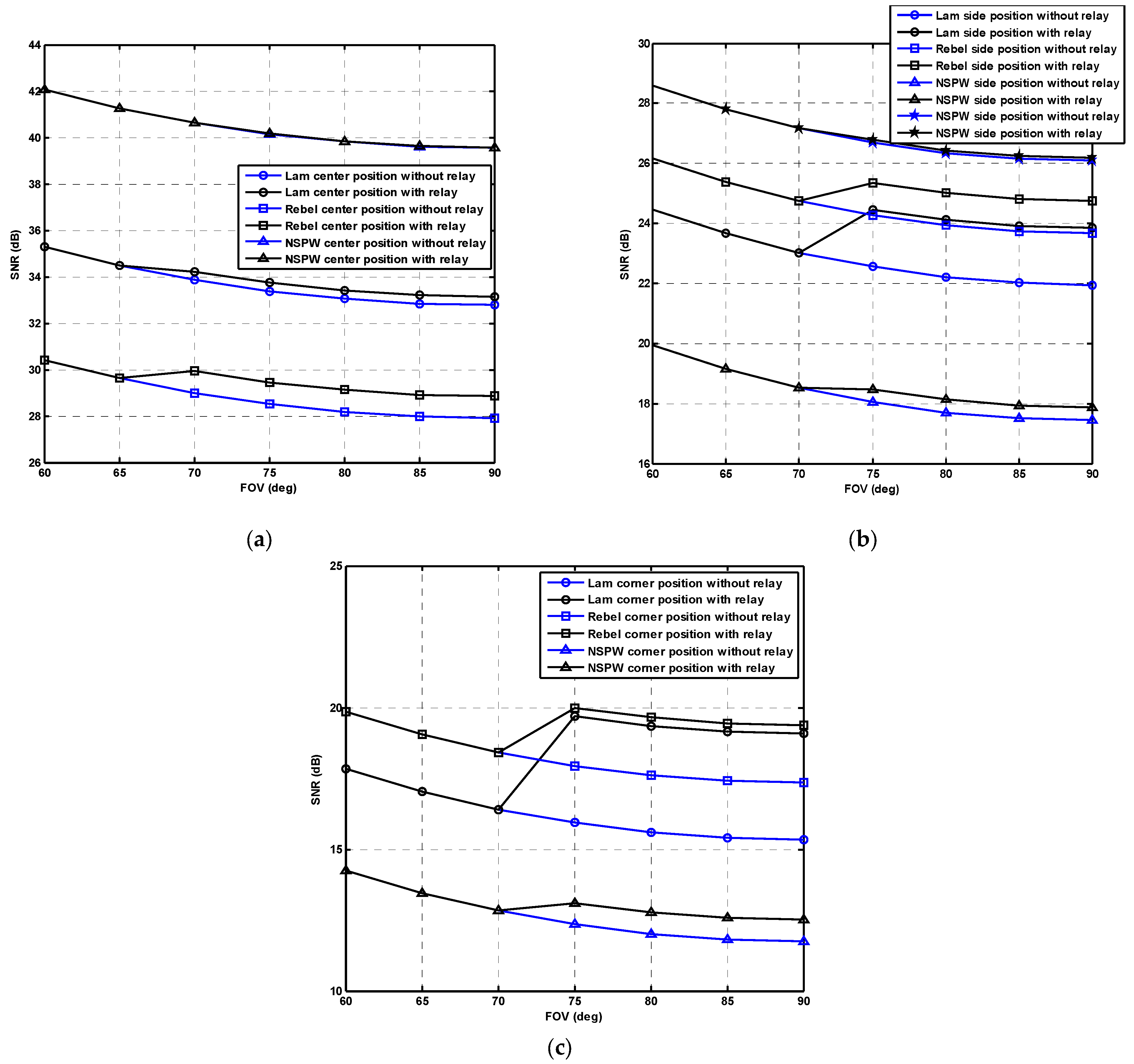
In this section, the numerical analysis is carried out between the conventional Lambertian beam configuration and the non-Lambertian optical beam configuration-based relay-assisted VLC systems. Specifically, one representative medium-sized indoor scenario is envisioned, which is consistent with the one in Figure 1, Figure 2 and Figure 3. Furthermore, the main parameters of the investigated relay-assisted VLC systems are included in Table 1. It must be noted that, objectively, no unit is needed for the number of transmitter, LED Lambertian index, and concentrator refractive index in Table 1. Therefore, all the parameters are well founded and are consistent with the published work, which includes, but is not limited to, the references [8,9,20,24,25]. Specifically, the room size is 5 × 5 × 3 m3, which is one typical VLC scenario with medium size [8,9]. Without loss of generality, only one transmitter is considered and mounted at the center of the ceiling [8,9], and the Lambertian index is 1, which represents the generalized Lambertian beam pattern [9,20]. At the receiver end, the height of the receiver is 0.85 m, which is consistent with the height of a typical office desk [24,25]. The response of PD for the relay and destination node is 0.53 A/W, the concentrator refractive index is 1.5, VLC noise power density is 1.0 × 10⁻²¹ W/Hz, and the LED modulation bandwidth is 20 MHz, which are all typical values for VLC systems, and are consistent with the reported works [20,24,25]. In Table 1, some parameters, including number of transmitter, LED Lambertian index, and concentrator refractive index, are without units, but are not missing units. All these three parameters are variables without units, which do not need units in physics.
Without loss of generality, the single LED transmitter is mounted on the center of the ceiling, while the relay is positioned at coordinates (1.6, 1.6, 1.35 m) with fixed height. In the following work, three typical receiver positions, including center receiver position, side receiver position, and corner receiver position, are adopted to comparatively evaluate the performance of relay-assisted VLC systems with distinct light beam patterns from different views. Accordingly, the coordinates for the mentioned three receiver positions are (2.5, 2.5, 0.85 m), (2.5, 0.5, 0.85 m), and (0.5, 0.5, 0.85 m), respectively. Moreover, due to the asymmetry of spatial radiation for the NSPW light beam, one additional side receiver position 2, i.e., (0.5, 2.5, 0.85 m), is introduced to sufficiently observe the relay VLC transmission performance at the neighbor-side position facing non-uniform radiation intensity from the emerging rotationally asymmetric non-Lambertian optical beam.
As for an amplify-and-forward mechanism of the relay node, which amplifies both signal and noise, it must be noted that the same amplify-and-forward mechanism is applied at the respective relay node of the concerned baseline Lambertian beam-based relay-assisted 6G visible light communication system, as shown in Figure 1; the novel LUXEON Rebel non-Lambertian beam-based relay-assisted 6G visible light communication system, as shown in Figure 2; and the novel asymmetric NSPW non-Lambertian beam-based relay-assisted 6G visible light communication system, as shown in Figure 3. Therefore, all the numerical results in this work objectively present the performance differences of the above three visible light communication systems using amplify-and-forward mechanism, sufficiently and fairly considering the potential effect of the noise amplification at the involved relay node. As for the so-called impact of noise amplification on the SNR and BER, we note that all the results of the SNR and the BER in the following Figure 4, Figure 5, Figure 6 and Figure 7 are obtained under the explicit consideration of the noise amplification at the involved relay node, but not in the absence of consideration of this degradation effect. Therefore, the recommended analysis of the SNR and BER with the impact of noise amplification can be found in the relevant content of Figure 4, Figure 5, Figure 6 and Figure 7.

3.1. Effect of FOV

In Figure 4, the SNR performance at the destination node versus the receiver FOV for the case of central position, side position, and corner position are presented separately. Specifically, for the central position, where the receiver FOV for relay and destination is simultaneously reduced from the original 60 to 90 deg, the received SNR for the conventional Lambertian optical beam configuration-based VLC system without relay assist is gradually reduced to 32.78 dB from the initial 35.28 dB, while the counterpart of the non-Lambertian LUXEON Rebel optical beam-based VLC system without relay assist is gradually reduced to 27.91 dB from the initial 30.41 dB, and the counterpart of the non-Lambertian NSPW optical beam-based VLC system without relay assist is gradually reduced to 39.55 dB from the initial 42.05 dB.
For the center position, as shown in Figure 4a, once the relay assist is applied in the above VLC systems, the respective performance gain can be separately identified if the needed FOV condition is satisfied. In detail, no gain is found until the FOV for relay and destination is increased to 70 deg, as no VLC signal is captured by the optical receiver of the VLC relay, which is independent of the specific light beam configuration. When the FOV for relay and destination reaches 70 deg, for the conventional Lambertian optical beam configuration-based VLC system, the received SNR is enhanced to 34.22 dB from 33.86 dB by applying the Lambertian relay assist, which means that about 0.36 dB received SNR gain is provided. Moreover, when the FOV for relay and destination is further increased to 90 deg, by applying the Lambertian relay assist, the received SNR is further changed to 33.14 dB, with up to 0.36 dB gain achieved for the received SNR. Similarly, for the non-Lambertian LUXEON Rebel optical beam configuration-based VLC system, as the FOV for relay and destination is up to 70 deg, the received SNR is enhanced to 29.94 dB from 28.99 dB by applying the non-Lambertian LUXEON Rebel relay assist, which means that about a 0.95 dB received SNR gain is provided. Moreover, when the FOV for LUXEON Rebel relay and destination is further increased to 90 deg, by applying the LUXEON Rebel relay assist, the received SNR is further changed to 28.86 dB, with up to 0.95 dB gain achieved for the received SNR. However, for the left case of non-Lambertian NSPW optical beam-based VLC system, the gain provided by the VLC relay assist is quite limited, as the original received SNR satisfies 39.55 dB for FOV of 90 deg, and 40.63 dB for FOV of 70 deg, which makes the relevant relay gain negligible.
For the side position, as shown in Figure 4b, once the relay assist is applied in the above VLC systems, a more obvious performance gain can be successfully realized if the FOV condition is no less than 75 deg. Accordingly, when the FOV for relay and destination is up to 75 deg, for the conventional Lambertian optical beam configuration-based VLC system, the received SNR is enhanced to 24.45 dB from 22.55 dB by applying the Lambertian relay assist, which means that about 1.90 dB received SNR gain is provided. Moreover, when the FOV for relay and destination is further increased to 90 deg, by applying the Lambertian relay assist, the received SNR is further changed to 23.84 dB, with an up to 1.90 dB gain achieved for the received SNR. Similarly, for the case of LUXEON Rebel optical beam configuration, as the FOV for relay and destination is up to 75 deg, the received SNR is enhanced to 25.36 dB from 24.27 dB by applying the LUXEON Rebel relay assist, which means that about a 1.09 dB received SNR gain is provided. Moreover, when FOV for both relay and destination is up to 90 deg, by applying the LUXEON Rebel relay, the received SNR is further changed to 24.76 dB, which means that up to a 1.10 dB gain is acquired for the received SNR. Distinctly, for the left case of non-Lambertian NSPW optical beam-based VLC system, an impressive difference for the performance and achievable gain can be observed for the mentioned side position and additional side receiver position 2. Specifically, for the side position, as the much weaker radiation intensity from the NSPW optical beam is faced by the VLC receiver, the received SNR with relay is limited to 18.46 dB and 17.86 dB for the FOV of 75 deg and 90 deg, respectively, while the achieved gain is up to 0.42 dB and 0.42 dB accordingly by applying the non-Lambertian NSPW relay assist. On the contrary, for the side position 2, as the much stronger radiation intensity from the NSPW optical beam is faced by the VLC receiver, the received SNR with relay is excellent, up to 26.77 dB and 26.17 dB for the FOV of 75 deg and 90 deg, respectively, while the achieved gain by relay is just about 0.08 dB and 0.09 dB accordingly, as it is quite challenging to further improve the SNR performance from the very high initial performance via the relay assistance.
For the more challenging corner position, as shown in Figure 4c, once the relay assist is applied in the above VLC systems, the intense performance gain can be obtained if the needed FOV condition is satisfied. Accordingly, when the FOV for relay and destination is up to 75 deg, for the conventional Lambertian optical beam configuration-based VLC system, the received SNR at the corner position is impressively enhanced to 19.69 dB from 15.93 dB by applying the Lambertian relay assist, which means that about 3.76 dB SNR gain is provided. Moreover, when the FOV for relay and destination is further increased to 90 deg, by applying the Lambertian relay assist, the received SNR at the corner position is further changed to 19.09 dB, with up to a 3.76 dB gain achieved for the received SNR. Similarly, for the case of the LUXEON Rebel optical beam configuration, as the FOV for relay and destination is up to 75 deg, the received SNR at corner position is enhanced to 19.99 dB from 17.95 dB by applying the LUXEON Rebel relay assist, which means that about a 2.04 dB received SNR gain is provided. Moreover, when the FOV for both relay and destination is up to 90 deg, by applying the LUXEON Rebel relay, the received SNR at the corner position is further changed to 19.39 dB, which means that up to a 2.05 dB gain is acquired for the received SNR at the corner position, as the sufficient VLC signal intensity is emitted to the far corner position via the cup-shaped radiation pattern of the LUXEON Rebel beam at the LED transmitter and relay transmitter. But for the left case of the non-Lambertian NSPW relay assist, the received SNR at the corner position is simultaneously limited by the long transmission path and the weak radiation intensity from the NSPW transmitter and relay to the direction of the room corner. Numerically, the respective received SNR with relay is just 13.10 dB and 12.50 dB for the FOV of 75 deg and 90 deg, respectively, while the achieved gain by relay is about 0.75 dB and 0.75 dB, accordingly.

3.2. Effect of Aperture Size

In Figure 5, the SNR performance at the destination node versus the receiver aperture size for the case of central position, side position, and corner position are presented separately. Firstly, when the optical receiver is located at the center position, as shown in Figure 5a, under the conventional Lambertian optical beam configuration, once the physical area of PD, also known as aperture size of the receiver and relay node, is simultaneously increased from the initial 0.5 cm2 to 1.5 cm2, the received SNR without the relay assist is enhanced from the initial 23.60 dB to 33.14 dB. Meanwhile, the received SNR with the relay assist is enhanced from the initial 23.24 dB to 32.78 dB, which means that the received SNR gain provided by the relay assist is changed from the initial 0.36 dB to 0.36 dB. At the same receiver position, if the novel LUXEON Rebel non-Lambertian optical beam configuration is adopted at the LED transmitter and the relay node, once the aperture size of the receiver and relay node is increased from the initial 0.5 cm2 to 1.5 cm2, the received SNR with the relay assist is gradually enhanced from the initial 19.31 dB to 28.86 dB, but the received SNR gain provided by the relay assist is still just 0.94 dB. As for the left case of non-Lambertian NSPW beam configuration at the LED transmitter and the relay node, if the aperture size is increased from the initial 0.5 cm2 to 1.5 cm2, the related SNR without and with the relay is enhanced from about 30.01 dB to 39.55 dB, which means that the SNR gain provided by the relay is negligible, as too much radiation intensity from the NSPW optical beam is projected to the ideal center receiver position.
Secondly, when the optical receiver is located at the side position, as shown in Figure 5b, under the conventional Lambertian optical beam configuration, once the aperture size is increased from the initial 0.5 cm2 to 1.5 cm2, the received SNR without the relay assist is enhanced from the initial 12.41 dB to 21.95 dB, while the received SNR with the relay assist is enhanced from the initial 14.29 dB to 23.84 dB, which indicates that the gain provided by the relay assist is slightly changed from the initial 1.88 dB to 1.89 dB. At this receiver position, if the novel LUXEON Rebel beam configuration is adopted at the transmitter and the relay node, with the aperture size increased from the initial 0.5 cm2 to 1.5 cm2, the received SNR with the relay assist is gradually enhanced from the initial 15.21 dB to 24.76 dB, but the gain provided by the relay assist remains at about 1.09 dB. As for the left non-Lambertian NSPW beam configuration, if the aperture size is varied from 0.5 cm2 to 1.5 cm2, the related SNR with the relay is enhanced from about 8.31 dB to 17.86 dB, and the gain from the relay assist remains at about 0.41 dB. Thanks to the spatial asymmetry of the NSPW beam, the received SNR with the relay assist at the additional side position 2 is up to a superior 16.63 dB, and this performance metric is further improved to 26.17 dB with the aperture size varied to a better 1.5 cm2, although the SNR gain presented is still about 0.09 dB during these various aperture size settings.
Thirdly, when the optical receiver is located at the more challenging corner position, as shown in Figure 5c, under the baseline Lambertian configuration, once the aperture size is increased from the initial 0.5 cm2 to 1.5 cm2, the received SNR without the relay assist is accordingly varied from 5.79 dB to 15.33 dB, while the received SNR with the relay assist enhanced from 9.53 dB to 19.09 dB, which means that the gain achieved by the relay assist remains at a decent 3.74 dB during this change process. If the beam configuration is replaced by the LUXEON Rebel option at the transmitter and relay node, with the aperture size at the receiver and relay node increased from the initial 0.5 cm2 to 1.5 cm2, the received SNR with the relay assist is gradually enhanced from the initial 9.83 dB to 19.39 dB, while the gain provided by the relay assist remains at about 2.03 dB. However, for the left option of NSPW beam configuration, with the aperture size increased from the initial 0.5 cm2 to 1.5 cm2, the received SNR with the relay assist is gradually changed from the initial 2.95 dB to 12.50 dB, while that gain from the relay assist remains at a mere 0.75 dB after the aperture size variation.

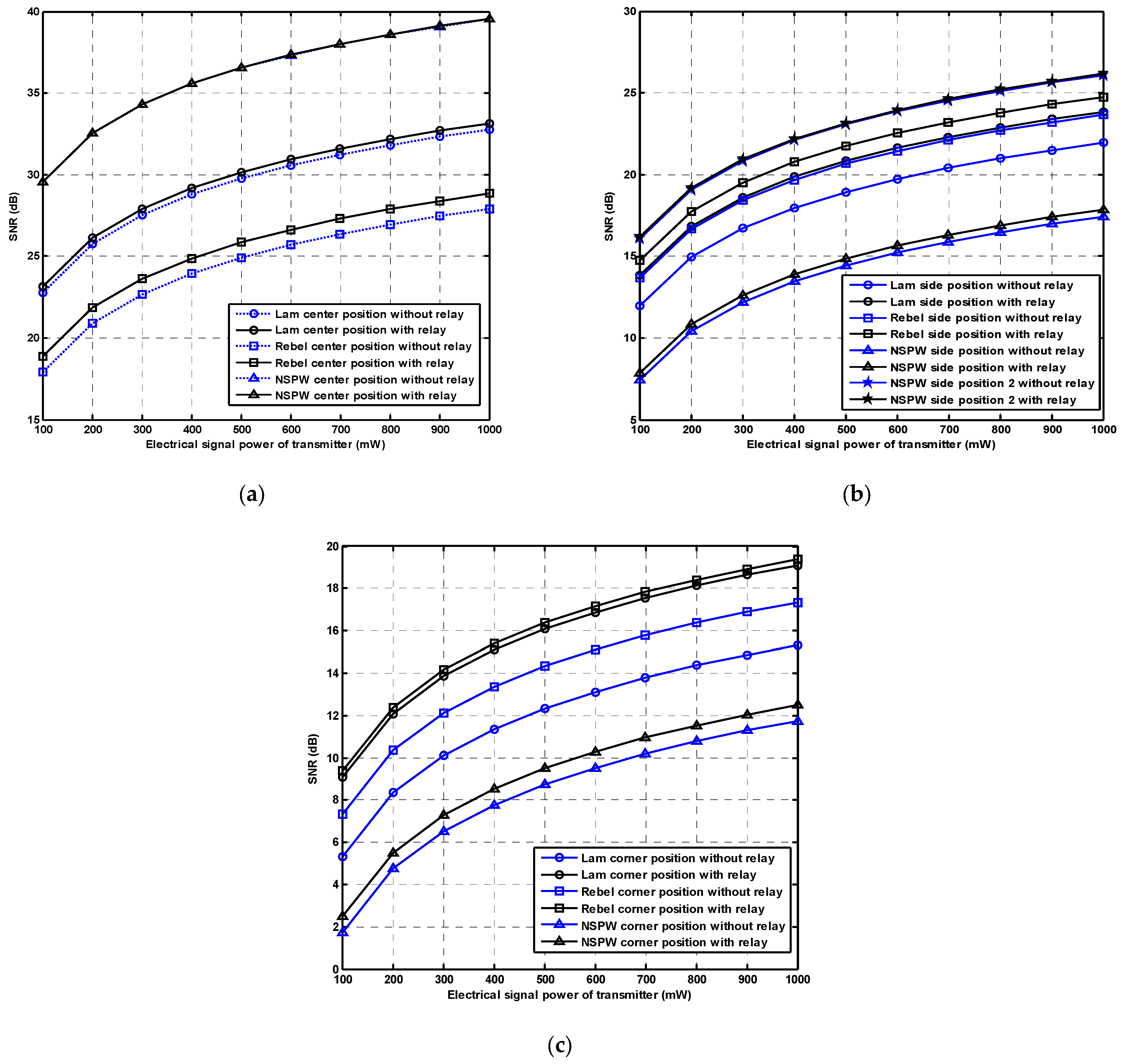
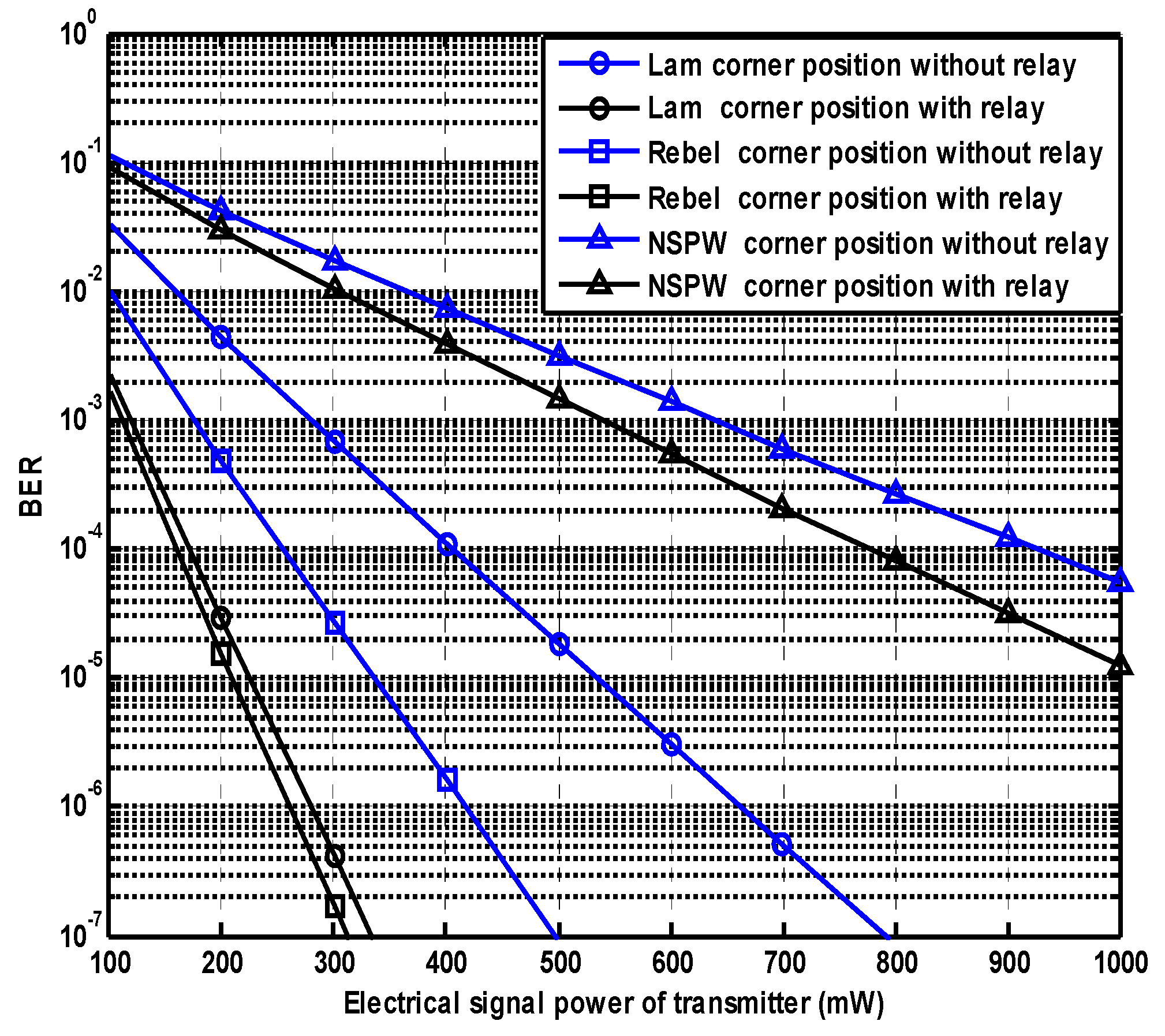
3.3. Effect of Emitted Signal Power

In Figure 6, the SNR performance at the destination node versus the emitted electrical signal power for the case of central position, side position, and corner position are presented separately. Specifically, as shown in Figure 6a of the central position, for the case of Lambertian beam configuration, once the emitted electrical signal power at the LED transmitter and relay node is simultaneously increased from the initial 100 mW to 1000 mW, the received SNR with the relay assist is enhanced from the initial 23.14 dB to 33.14 dB, which indicates that the respective relay assist gain is still the initial 0.36 dB. At this ideal central position, if the LUXEON Rebel beam is applied at the transmitter and the relay node, with the emitted electrical signal power increased from 100 mW to 1000 mW at the LED transmitter and relay node, the received SNR with the relay assist is gradually enhanced from the initial 18.85 dB to 28.86 dB, and the respective SNR gain provided by relay remains at about 0.94 dB. As for the left NSPW beam configuration, with the abovementioned variation of the emitted signal power, the related SNR with the relay is enhanced from an excellent 29.56 dB to 39.56 dB; however, the gain from the relay assist is almost negligible.
For the side position, as shown in Figure 6b, under the conventional Lambertian optical beam configuration, once the emitted electrical signal power is increased from 100 mW to 1000 mW, the received SNR with the relay assist is enhanced from the initial 13.83 dB to 23.84 dB, while the gain provided by the relay assist remains at about 1.88 dB with different emission power level. At this receiver position, if the LUXEON Rebel configuration is adopted at the transmitter and the relay node, with the emission power increased from the initial 100 mW to 1000 mW, the received SNR with the relay assist is gradually enhanced from the initial 14.75 dB to 24.76 dB, but the achieved gain via the relay assist remains at about 1.09 dB. As for the left non-Lambertian NSPW configuration, if the emission power is increased from the initial 100 mW to 1000 mW, the related SNR with the relay is enhanced from about 7.86 dB to 17.86 dB, and the gain from the relay assist remains at just 0.42 dB. Thanks to the spatial asymmetry of the NSPW beam, the received SNR with the relay assist at the additional side position 2 is up to a superior 16.17 dB, and this performance metric is further improved to 26.17 dB with the emission power varied to a better 1000 mW, although the SNR gain presented is still about 0.09 dB during these various emission power settings.
For the corner position, as shown in Figure 6c, under the baseline Lambertian configuration, once the emission power is increased from the initial 100 mW to 1000 mW, the received SNR with the relay assist is enhanced from 9.07 dB to 19.09 dB, but the gain achieved by the relay assist remains at a decent 3.74 dB during this change process. If the beam configuration is replaced by the LUXEON Rebel option at the transmitter and relay node, with the emission power increased from the initial 100 mW to 1000 mW, the received SNR with the relay assist is gradually enhanced from the initial 9.37 dB to 19.39 dB; however, the gain provided by the relay assist remains at about 2.03 dB. Furthermore, for the left option of the NSPW beam configuration, with the emission power increased from the initial 100 mW to 1000 mW, the received SNR with the relay assist is gradually enhanced from the initial 2.49 dB to 12.50 dB, but the gain provided by the relay assist remains at about 0.74 dB.
To compare the BER performance of relay VLC systems with different beam configurations, the BER curves at the corner destination node versus the emitted electrical signal power are illustrated in Figure 7. For the case of the baseline Lambertian configuration with relay assist, to achieve the targeted BER of 10−4, the needed simultaneous electrical signal power at the transmitter node is about 170 mW, while the needed electrical signal power at the transmitter is increased to 400 mW once the relay assist is not available. On the other hand, for the case of the LUXEON Rebel configuration with relay assist, to achieve the targeted BER of 10−4, the needed signal power at the transmitter node is just 140 mW, while the needed power at the transmitter is increased to 260 mW once the relay assist is not available. Finally, for the case of the NSPW configuration with relay assist, to achieve the targeted BER of 10−4, the needed signal power at the transmitter and relay node is up to 770 mW, while the needed power at the transmitter is simultaneously further increased to 920 mW once the relay assist is absent.
It must be noted that the topic of this work is non-Lambertian relay-assisted 6G visible light communication, but not the well-reported basic non-Lambertian VLC. The coverage, alignment, and complexity issues of the basic non-Lambertian VLC have been well investigated and explored by the works of Prof. Jupeng Ding and his research team. If the individual reviewer and the potential readers are interested in the coverage, alignment, and complexity issues of the basic non-Lambertian VLC, they are encouraged to read and study the excellent and pioneering works of Prof. Jupeng Ding and his research team, which include, but are not limited to, references [22,23,24,25] of this article.

4. Conclusions

This work was motivated by the applicability limitation of the conventional Lambertian relay-aided VLC technique schemes, which are unable to adapt to the diverse non-Lambertian transmitter scenarios. In this work, the typical non-Lambertian transmitter and relay were utilized to configure the relay-aided VLC links. For the corner receiver position, to achieve the targeted BER of 10−4, the needed simultaneous electrical signal power at the transmitter node is about 140 mW for the case of the LUXEON Rebel configuration, while the counterpart of the benchmark Lambertian relay link is more than 170 mW. In the near future work for 6G network, the exploration of relay-assisted diverse non-Lambertian VLC could be further extended to customized beam forming, beam cooperation, dynamic beam configuration, beam switching, resource allocation, reconfigurable multiple-input multiple-output, and other key techniques design.

Author Contributions

J.D. determined the theme and structure of the article, provided professional knowledge in the field of visible light communications, wrote and modified the article, and replied to comments from editors and reviewers. C.-L.I. provided theoretical knowledge of mobile communication and wireless communication. J.W. found the literature, participated in the discussion, and wrote some of the content. H.Y. looked for the literature, participated in the discussion. All authors have read and agreed to the published version of the manuscript.

Funding

This work was supported in part by the National Natural Science Foundation of China (Grants No. 62061043), Yantai Nanshan University Research and Development Fund Project (Grants No. 2025KJ01001), Tianshan Cedar Project of Xinjiang Uygur Autonomous Region (Grants No. 2020XS27), and High-level Talents Introduction Project in Autonomous Region (Grants No. 042419004).

Institutional Review Board Statement

Not applicable.

Informed Consent Statement

Not applicable.

Data Availability Statement

Data are contained within the article.

Conflicts of Interest

The authors declare no conflicts of interest.

References

  1. Zhang, Y.; Zhang, H.; Cosmas, J.; Jawad, N.; Ali, K.; Meunier, B.; Kapovits, A.; Huang, L.K.; Li, W.; Shi, L.; et al. Internet of radio and light: 5G building network radio and edge architecture. Intell. Converg. Netw. 2020, 1, 37–57. [Google Scholar] [CrossRef]
  2. Chowdhury, M.Z.; Hossan, M.T.; Islam, A.; Jang, Y.M. A comparative survey of optical wireless technologies: Architectures and applications. IEEE Access 2018, 6, 9819–9840. [Google Scholar] [CrossRef]
  3. Sun, S.; Yang, F.; Song, J. Sum rate maximization for intelligent reflecting surface-aided visible light communications. IEEE Commun. Lett. 2021, 25, 3619–3623. [Google Scholar] [CrossRef]
  4. Sun, S.; Wang, T.; Yang, F.; Song, J.; Han, Z. Intelligent reflecting surface-aided visible light communications: Potentials and challenges. IEEE Veh. Technol. Mag. 2022, 17, 47–56. [Google Scholar] [CrossRef]
  5. Wang, T.; Yang, F.; Song, J.; Han, Z. Dimming Techniques of Visible Light Communications for Human-Centric Illumination Networks: State-of-the-Art, Challenges, and Trends. IEEE Wirel. Commun. 2020, 27, 88–95. [Google Scholar] [CrossRef]
  6. Eltokhey, M.W.; Alouini, M.-S. Searchlight-Assisted Feeder Links for UAV-Based VLC Networks. IEEE Commun. Mag. 2025, 63, 158–164. [Google Scholar] [CrossRef]
  7. Hamza, A.S.; Deogun, J.S.; Alexander, D.R. Classification framework for free space optical communication links and systems. IEEE Commun. Surv. Tuts. 2019, 21, 1346–1382. [Google Scholar] [CrossRef]
  8. Kizilirmak, R.C.; Narmanlioglu, O.; Uysal, M. Relay-Assisted OFDM-Based Visible Light Communications. IEEE Trans. Commun. 2015, 63, 3765–3778. [Google Scholar] [CrossRef]
  9. Oliveira, M.; Monteiro, P.; Pohl, A. Performance Improvement of VLC Systems Employing an Amplify-and-Forward Scheme. In Proceedings of the 2019 22nd International Symposium on Wireless Personal Multimedia Communications (WPMC), Lisbon, Portugal, 24–27 November 2019; IEEE: New York, NY, USA, 2019. [Google Scholar]
  10. Zhu, M.; Wang, Y.; Liu, X.; Ma, S.; Zhang, X.; Fu, Y. Performance Analysis for DF Relay-aided Visible Light Communication System with NOMA. IEEE Photonics J. 2022, 14, 7350809. [Google Scholar] [CrossRef]
  11. Zhang, C.; Ye, J.; Pan, G.; Ding, Z. Cooperative Hybrid VLC-RF Systems with Spatially Random Terminals. IEEE Trans. Commun. 2018, 66, 6396–6408. [Google Scholar] [CrossRef]
  12. Zhang, C.; Ye, J.; Shi, J.; Pan, G.; Li, Z.; Ding, Z. Cooperative Hybrid VLC-RF Systems for WSNs. In Proceedings of the 2018 Asia-Pacific Signal and Information Processing Association Annual Summit and Conference (APSIPA ASC), Honolulu, HI, USA, 12–15 November 2018; IEEE: New York, NY, USA, 2018. [Google Scholar]
  13. Vikramaditya, S.; Sewaiwar, A.; Chung, Y. An Efficient Repeater Assisted Visible Light Communication. In Proceedings of the European Wireless 2015, Budapest, Hungary, 20–22 May 2015; IEEE: New York, NY, USA, 2015. [Google Scholar]
  14. Ren, B.; Bai, Z.; Yang, Y.; Pang, K.; Sun, S.; Han, T.; Kwak, K. Enhanced Performance of Indoor Cooperative IHDAF Protocol Based SM VLC System. In Proceedings of the 2018 IEEE 18th International Conference on Communication Technology (ICCT), Chongqing, China, 8–11 October 2018; IEEE: New York, NY, USA, 2018. [Google Scholar]
  15. Kazemi, H.; Safari, M.; Haas, H. A Wireless Optical Backhaul Solution for Optical Attocell Networks. IEEE Trans. Wirel. Commun. 2018, 18, 807–823. [Google Scholar] [CrossRef]
  16. Kazemi, H.; Safari, M.; Haas, H. A wireless backhaul solution using visible light communication for indoor Li-Fi attocell networks. In Proceedings of the 2017 IEEE International Conference on Communications (ICC), Paris, France, 21–25 May 2017; IEEE: New York, NY, USA, 2017. [Google Scholar]
  17. Ndjiongue, A.R.; Ngatched, T.M.N.; Ferreira, H.C. AF Cooperative VLC Communication Systems: Cascaded Channel Analysis. In Proceedings of the ICC 2019–2019 IEEE International Conference on Communications (ICC), Shanghai, China, 20–24 May 2019; IEEE: New York, NY, USA, 2019. [Google Scholar]
  18. Al-khori, J.; Nauryzbayev, G.; Abdallah, M.; Hamdi, M. Joint Beamforming Design and Power Minimization for Friendly-Jamming Relaying Hybrid RF/VLC Systems. IEEE Photonics J. 2019, 11, 7902718. [Google Scholar] [CrossRef]
  19. Eso, E.; Zabih, G.; Zvanovec, S.; Pesek, P.; Sathian, J. Vehicle-to-Vehicle Relay-Assisted VLC With Misalignment Induced Azimuth or Elevation Offset Angles. IEEE Photonics Technol. Lett. 2021, 33, 908–911. [Google Scholar] [CrossRef]
  20. Komine, T.; Nakagawa, M. Fundamental analysis for visible-light communication system using LED lights. IEEE Trans. Consum. Electron. 2004, 50, 100–107. [Google Scholar] [CrossRef]
  21. Moreno, I.; Sun, C.-C. Modeling the radiation pattern of LEDs. Opt. Exp. 2008, 16, 1808–1819. [Google Scholar] [CrossRef] [PubMed]
  22. Ding, J.; I, C.-L.; Xu, Z. Indoor optical wireless channel characteristics with distinct source radiation patterns. IEEE Photonics J. 2016, 8, 7900115. [Google Scholar] [CrossRef]
  23. Ding, J.; I, C.L.; Xie, R.; Lai, H.; Zhang, C. Actual radiation patterns-oriented non-deterministic optical wireless channel characterization. In Proceedings of the Springer Chinese Conference on Biometric Recognition, Urumchi, China, 11–12 August 2018; Springer: Berlin, Germany, 2018. [Google Scholar]
  24. Ding, J.; I, C.-L.; Wang, J.; Yang, H. Optical beams switching-based coverage enhancement scheme for compact visible light communications. IEEE J. Light. Technol. 2022, 40, 6139–6150. [Google Scholar] [CrossRef]
  25. Ding, J.; I, C.-L.; Wang, J.; Yang, H.; Wang, L. Multiple optical beam switching for physical layer security of visible light communications. IEEE Photonics J. 2022, 14, 7306209. [Google Scholar] [CrossRef]
  26. Sun, C.C.; Lee, T.X.; Ma, S.H.; Lee, Y.L.; Huang, S.M. Precise optical modeling for LED lighting verified by cross correlation in the midfield region. Opt. Lett. 2006, 31, 2193–2195. [Google Scholar] [CrossRef] [PubMed]
  27. Chien, W.T.; Sun, C.C.; Moreno, I. Precise optical model of multi-chip white LEDs. Opt. Express 2007, 15, 7572–7577. [Google Scholar] [CrossRef] [PubMed]
Figure 1. Schematic of relay-assisted VLC employing benchmark Lambertian beams for 6G IoT application. It should be emphasized that the benchmark Lambertian beam configuration, but not the non-Lambertian beam configuration, is adopted at the LED transmitter and relay.
Photonics 12 00541 g001
Figure 2. Schematic of relay-assisted VLC employing LUXEON Rebel beams for 6G IoT application. It should be emphasized that, unlike Figure 1, the LUXEON Rebel non-Lambertian beam configuration, but not the Lambertian beam configuration, is adopted at the LED transmitter and relay.
Photonics 12 00541 g002
Figure 3. Schematic of relay-assisted VLC employing asymmetric NSPW beams for 6G IoT application. It should be emphasized that, unlike Figure 1, the asymmetric NSPW non-Lambertian beam configuration, but not the Lambertian beam configuration, is adopted at the LED transmitter and relay.
Photonics 12 00541 g003
Figure 4. SNR performance at the destination node versus the receiver FOV for the case of (a) central position, (b) side position, and (c) corner position.
Photonics 12 00541 g004
Figure 5. SNR performance at the destination node versus the aperture size for the case of (a) central position, (b) side position, and (c) corner position.
Photonics 12 00541 g005
Figure 6. SNR performance at the destination node versus the emitted electrical signal power for the case of (a) central position, (b) side position, and (c) corner position.
Photonics 12 00541 g006
Figure 7. BER performance at the destination node versus the emitted electrical signal power.
Photonics 12 00541 g007
Table 1. Main parameters configuration.
ParametersValues
Room size (W × L × H)5 × 5 × 3 m3
Electrical signal power of source and relay node1 W
Number of transmitter1
Location of transmitter(2.5, 2.5, 3) m
LED Lambertian index1
Electrical to optical coefficient of the source and relay node0.5 W/A
Receiver field of view90°
Height of receiving plane0.85 m
Physical area of PD1.5 cm2
Responsively of PD for the relay and destination node0.53 A/W
Concentrator refractive index1.5
LED modulation bandwidth20 MHz
VLC noise power density1.0 × 10−21 W/Hz
Location of relay(1.6, 1.6, 1.35) m
Disclaimer/Publisher’s Note: The statements, opinions and data contained in all publications are solely those of the individual author(s) and contributor(s) and not of MDPI and/or the editor(s). MDPI and/or the editor(s) disclaim responsibility for any injury to people or property resulting from any ideas, methods, instructions or products referred to in the content.

