1. Introduction
For a long time, four-wave mixing (FWM) has attracted the attention of numerous researchers due to its ability to manipulate information and transfer energy between optical fields of different frequencies and/or polarizations [
1,
2]. However, implementing FWM in conventional media faces challenges of weak nonlinear responses and significant resonant absorption, typically requiring high-intensity lasers or materials with special symmetries to enhance atom–light interactions. This limitation can be overcome by exploiting the effect of electromagnetically induced transparency (EIT) [
3], which introduces a control field in multilevel atomic systems to suppress linear absorption at near-resonant frequencies via quantum destructive interference, thus enabling a coherent FWM of weak light signals via enhanced nonlinear susceptibility [
4,
5]. In view of this fact, EIT-based FWM in multilevel atomic systems has attracted broad interest recently, with most efforts focusing on exploring various laser coupling schemes [
6,
7,
8,
9,
10,
11] that enable important applications, including frequency conversion [
11,
12], squeezed light or biphoton generation [
13,
14], optical storage or quantum memory [
15,
16], and nonlinear optical amplification [
17,
18]. As a result, FWM continues to be a highly relevant research topic, promising the development of advanced optical devices and quantum technologies, especially when working media like Rydberg atoms or driving schemes like non-Hermitian optics are incorporated [
19,
20].
On the other hand, optically tunable parity-time (
) symmetry and antisymmetry, as typical non-Hermitian effects, have been extensively studied in various EIT systems by making the control field and another external field exhibit out-of-phase spatially periodic modulations [
21,
22,
23,
24,
25,
26,
27,
28,
29,
30,
31]. Leveraging
symmetry and antisymmetry, a series of nontrivial optical phenomena can be achieved, including unidirectional reflectionless (URL) [
25,
26,
27], asymmetric perfect absorption (APA) [
27,
28], and asymmetric diffraction [
29,
30,
31]. This benefits indeed from the unusual feature
for
-symmetric systems while
for
-antisymmetric systems with
being the complex susceptibility of a probe field at position
r in an EIT medium. As far as we know, most non-Hermitian EIT studies focus on the linear regime because out-of-phase spatially periodic modulations of two external fields have already introduced abundant nontrivial optical phenomena along with theoretical and experimental complexities. Undoubtedly, if extended to the nonlinear regime, non-Hermitian EIT studies will significantly enhance the likelihood of realizing a broader spectrum of nontrivial optical phenomena, facilitating the development of advanced optical devices with multiple nonreciprocal scattering channels.
In this work, we consider a four-level double- scheme of cold 87Rb atoms driven by two strong fields (coupling or dressing) and two weak fields (probe or signal) to facilitate desired non-Hermitian FWM processes. We find that it is viable to realize a non-Hermitian atomic device exhibiting four scattering channels with respect to the probe and signal fields—direct and cross transmission as well as direct and cross reflection—when the coupling and dressing fields are set in the phase-mismatched standing-wave (SW) pattern. It is of more interest that one or two of the four output fields—forward and backward probes as well as forward and backward signals—may be quenched when both probe and signal input fields come from one side of this atomic sample. Such nonreciprocal scattering behaviors can be classified into ’single-color unidirectional transport’, ’dual-color unidirectional transport’, and ’single-color directional blockade’, all of which arise from perfect destructive interference between relevant cross and direct scattering channels. Beyond expanding the scope of non-Hermitian optics into the nonlinear regime, our findings provide a theoretical blueprint for multi-channel scattering devices with all-optical tunability.
2. Model and Equations
We start by considering a four-level atomic system in the double-
configuration as shown in
Figure 1a, where a probe field and a signal field of frequencies (amplitudes)
and
(
and
) drive, respectively, transitions
and
, while a coupling field and a dressing field of frequencies (amplitudes)
and
(
and
) drive, respectively, transitions
and
. These coherent light fields exhibit detunings (Rabi frequencies)
,
,
, and
(
,
,
, and
) with
(
) being resonant frequencies (dipole moments) on relevant atomic transitions. To avoid drive wrong transitions, each light field can be chosen with an appropriate polarization when the frequency difference between levels
and
is large enough, as detailed at the beginning of the next section. Two distinct FWM pathways are enabled in this system, governed by the energy conservation condition of
. One follows the transition sequence
, starting by absorbing
photons and ending at emitting
photons. The other proceeds via
, starting by absorbing
photons and ending at emitting
photons. Significantly, in addition to inevitably existent direct transmission channels (referring to
or
photons transmitting directly without frequency conversion), the two FWM pathways introduce cross transmission channels (referring to
photons being converted into
photons and then transmitted, or vice versa), which are inherently absent in traditional linear EIT systems where the probe and signal fields propagate independently.
We further assume that the coupling and dressing fields are in the SW pattern with
where
and
represent the wavenumbers, while
refers to a phase shift. In fact, both
and
are formed by two retroreflected light beams, which propagate along the
directions with the
and
wavenumbers, so that the probe and signal fields experience Bragg reflection and FWM in four different ways. Therefore, the two SW driving fields open up direct reflection channels (referring to
or
photons reflecting directly without frequency conversion), which cannot be achieved by traveling wave (TW) driving fields. Notably, we may take
, which is crucial for ensuring a common Bragg condition for both probe and signal fields so that their reflections can be simultaneously enhanced. Although
and
are slightly different,
can be achieved through experimentation by carefully adjusting the small angles
and
of the SW coupling and dressing fields with respect to the
z direction. Last but not least, the interplay between coherent FWM and Bragg reflection can give rise to a class of extra nontrivial scattering channels, namely cross reflection channels (referring to
photons being converted into
photons and then reflected, or vice versa).
Under both electric-dipole and rotating-wave approximations, with the above considerations, we can write down the Hamiltonian in the interaction picture as follows:
where
and
are two-photon and three-photon detunings, respectively. To account for population decay and coherence dephasing, respectively, with rates
and
, we introduce the Lindblad superoperator
, which, together with
, can be employed to derive a set of dynamical equations governing the 16 density matrix elements
associated with the double-
configuration in
Figure 1(a). In the limit of weak probe and signal fields (
) of interest, to the first-order of
and
, it is appropriate to set
and
so that these dynamical equations of density matrix elements reduce to
Setting
in the above equations, it is easy to cast the first-order steady-state solutions for the probe and signal coherences into a matrix form:
with
and
for the two diagonal elements while
for the common off-diagonal element and
for the common denominator. We have also defined the complex dephasing rates
,
, and
for the spin (
), probe (
), and signal (
) coherences, respectively, with
usually negligible because it is typically at least three-order of magnitude smaller than
.
The diagonal (direct) terms
and
are the only ones that would survive in the absence of dressing and coupling fields, while the off-diagonal (crossed) terms
would vanish. Nonlinear wave-mixing effects mediated by these crossed terms play a key role in the scattering processes represented by Equation (
4). It is worth noting that the signal affects the spatial distribution of the probe’s coherence (polarization) in much the same way as the probe affects the spatial distribution of the signal’s coherence. Such a symmetrical mutual influence—at least under the first-order approximation of
and
—is explicitly represented by two identical anti-diagonal matrix elements in Equation (
4). When the dressing field vanishes,
in Equation (
4) reduces to
, viz., the familiar coherence expression of a three-level
linear EIT system. Similarly, we have
when there is no coupling field. In such linear EIT systems, significant advances have been made in achieving optically tunable
symmetry or antisymmetry by exploiting the out-of-phase spatial modulation techniques [
21,
22,
23,
24,
25,
26,
27,
28,
29,
30,
31]. Prompted by these advances, we now leverage the spatially mismatched SW coupling and dressing fields in the nonlinear FWM system shown in
Figure 1a to attain a
non-Hermitian optical response. This can be performed by shifting
and
by
, which clearly provides control capabilities beyond those of traditional linear systems.
Then, we build on a recent work [
32] where only a probe
or a signal enters the atomic sample to further address a new scenario where scattering involves instead of
both probe and signal impinging simultaneously. A sketch of the scattering region (
) is shown in
Figure 1b, where the incident probe and signal pair—depicted as straight arrows—can enter from either left or right, while the four scattering channels—represented by wavy arrows—denote the outgoing waves after scattering. For the left incident case, viz.,
and
, the scattered fields comprise the
transmitted pair
, arising from the interference between direct and cross transmission channels, and the
reflected pair
that arise instead from the interference between direct and cross reflection channels (see the upper panel). Conversely, for the right incident case, viz.,
and
, our non-Hermitian FWM scattering entails the transmitted pair
and the reflected pair
(see the lower panel). The two scattered pairs
and
are characterized by the following synthetic transmission and reflection coefficients (incidence from the left):
with
, or else (incident from the right)
with
. Here,
and
(
and
) represent the transmission (reflection) amplitudes for a left-input probe field, quantifying the direct and cross transmission (reflection) channels, respectively. The same definitions apply to
and
(
and
), yet for a left-input signal field. Symmetrically, when the probe and signal fields are input from the right side, analogous transmission and reflection amplitudes can be defined by swapping the two input directions with ‘
’.
All 16 transmission and reflection amplitudes inside the square brackets of Equations (
5) and (
6) can be computed by solving the steady-state Maxwell equations under the slowly varying envelope approximation with the consideration that both probe and signal fields contain forward
and backward
components. The polarization functions required to solve these Maxwell equations are
and
with
N being the atomic density. They are here computed through the Fourier expansions of their space-dependent components according to
, where
and the zeroth-order
and the first-order
components are given by
with
being the common period of SW coupling and dressing fields. The coupled equations for the four-mode (probe and signal) electric fields
involved in the non-Hermitian FWM scattering process can be numerically solved under the condition of perfect phase matching (
):
with
and
. Here, we do not include a nonzero
because its main effect is to reduce the nonlinear conversion efficiency, as shown in [
2,
33], considering TW driving fields in an FWM process. A formal integration of this equation as detailed in Ref. [
32] yields a
transfer matrix
that relates the electric fields
at two boundaries
and
. By applying single-input field boundary conditions adopted here (
i)
and
; (
)
and
; (
)
and
; (
)
and
, we could obtain with the help of the transfer-matrix elements
the 16 complex amplitudes
with
[
32] inside the square brackets of Equations (
5) and (
6) and, in turn, the 8 synthetic reflection and transmission coefficients
with
.
3. Results and Discussion
In this section, our goal is to explore a few nonreciprocal scattering phenomena based on coherent FWM attained with out-of-phase periodic coupling and dressing fields, in the specific case where a probe field and a signal input field impinge upon the atomic sample from either the left or right side. We choose the D1 line of
87Rb atoms as an example by taking
,
,
, and
for the double-
system in
Figure 1a. This then yields a frequency difference of 816 MHz between levels
and
, while
GHz between levels
and
[
34], with the probe and coupling fields being in the
polarization, and the signal and dressing fields being in the
polarization. In this regard, we can make each optical field drive a desired transition, yet with negligible influences on all other transitions, either due to excessively large detunings or improper polarizations. Moreover, we have dephasing rates
kHz and
MHz, transition wavelengths
nm, and dipole moments
C·m [
34].
To validate the non-Hermitian properties induced by out-of-phase periodic coupling and dressing fields, we plot in
Figure 2 the moduli of all transmission and reflection amplitudes against the probe detuning
for symmetric driving fields of
and
. We also take
as a representative case because it corresponds to the most pronounced non-Hermitian spatial modulation maximizing the nonreciprocal scattering effects. As predicted in the last section, by combining nonlinear frequency conversion with Bragg reflection, we observe not only the omnipresent direct transmission amplitudes
but also the nonzero cross transmission amplitudes
, direct reflection amplitudes
, and cross reflection amplitudes
. A notably interesting fact is that nonreciprocal behaviors occur for both cross transmissions and direct reflections with
and
(compare the red solid and blue dashed lines), while the direct transmissions and cross reflections are reciprocal with
and
(see the black solid lines). Moreover, we have an invariance upon the simultaneous exchange of input frequencies and directions with
,
,
, and
. However, by applying asymmetric driving parameters (
or
), we can not only break this invariance but also violate the reciprocity of cross reflections, resulting in
. This will be further clarified in subsequent discussion on synthetic transmission and reflection coefficients.
Based on above nonreciprocal transmission and reflection amplitudes, four completely nonreciprocal output states with
,
,
, and
can be obtained by comparing the case of
and
with the case of
and
. This means that the probe and signal input fields coming from the left side and those coming from the right side should have identical amplitudes and phases when we make the comparison. We expect in particular that, when
and
as well as
and
satisfy specific conditions, perfect destructive interference may occur between relevant direct and cross scattering channels [see Equations (
5) and (
6)] to result in the quenching of one or two of the four (two probe and two signal) output fields. This then enables an interesting transition from nonreciprocal to unidirectional scattering behaviors, which will be validated through subsequent numerical results.
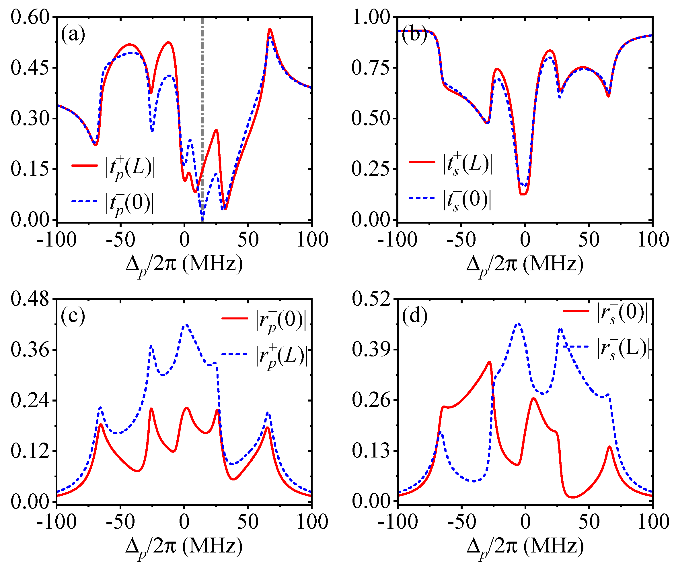
First, we try to prove that one of the four output fields can be quenched when the two input fields come from the right side but remains observable like others when the two input fields come from the left side. Such a single-color unidirectional transport, attained with symmetric driving parameters, is shown in
Figure 3 by quenching the left probe output field
at a specific probe detuning for two right input fields
and
as an example. We find from the blue dashed lines that
tends to be vanishing, while
,
, and
are clearly nonzero, at
MHz [denoted by the vertical gray line in (a)] when the two right input fields exhibit an amplitude ratio
and a phase difference
. Meanwhile, we find from the red solid lines that all output fields are observable at the same probe detuning when the two input probe fields come from the left side with the same amplitude ratio and phase difference. Though not shown here, we note that it is also viable to obtain
,
, or
by modulating the two right input fields in amplitude and phase, or achieve the same quenching results by modulating the two left input fields in amplitude and phase. Each of these single-color unidirectional transport behaviors is a result of perfect destructive interference between nonreciprocal reflection (
or
) or transmission (
or
) amplitudes, which is straightforward to understand by resorting to Equations (
5) and (
6).
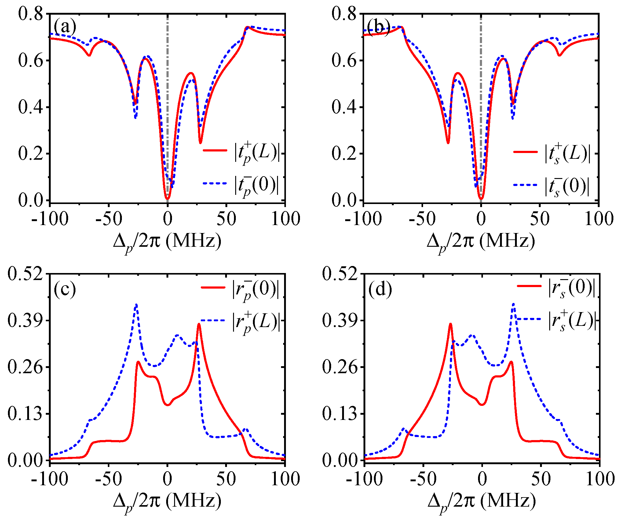
Second, we try to prove that two output fields on the same side can be quenched when the two input fields come from the left side but remain observable when the two input fields come from the right side. Such a dual-color unidirectional transport, attained also with symmetric driving parameters, is shown in
Figure 4 by quenching the right output fields
and
at a specific probe detuning for two left input fields
and
as an example. It is easy to find from the red solid lines that both
and
tend to be vanishing, while
and
are evidently nonzero, at
MHz [denoted by the vertical gray lines in (a) and (b)] when the two left input fields exhibit an amplitude ratio
and a phase difference
. Meanwhile, we find from the blue dashed lines that all output fields are observable at the same probe detuning when the two input probe fields come from the right side with the same amplitude ratio and phase difference. Though not shown here, it is also viable to obtain
and
by modulating the two left input fields in amplitude and phase, or achieve the same nonreciprocal quenching results by modulating the two right input fields in amplitude and phase. Both types of dual-color unidirectional transport can also be attributed to a perfect destructive interference, which, however, involves either two pairs of nonreciprocal reflection (
and
) or transmission (
and
) amplitudes in Equations (
5) and (
6).
Finally, we try to prove that one of the four output fields can be quenched with the other three being always observable regardless of whether the two input fields come from the left side or the right side. Such a single-color directional blockade, attained with asymmetric driving parameters (
) instead, is shown in
Figure 5 by quenching the left probe output field
at a specific probe detuning in both cases of two left input fields
and two right input fields
as an example. It is easy to find from the blue dashed lines that
tends to be vanishing, while
,
, and
are clearly nonzero, at
MHz [denoted by the vertical gray line in (a)] for two right input fields with
and
. It is also evident from the red solid lines that
tends to be vanishing, while
,
, and
are clearly nonzero, at
MHz [denoted by the vertical gray line in (c)] for two left input fields with
and
. The single-color directional blockade featured by both
and
is also resulted from perfect destructive interference, which further involves nonreciprocal cross reflections (
) in addition to nonreciprocal direct reflections (
) and nonreciprocal cross transmissions (
) due to asymmetric driving parameters. Though not shown here, we have checked that it is also viable to obtain
,
, or
regardless of whether the two input fields with appropriate amplitude ratios and phase differences come from the left side or right side.


