Abstract
Nonlinear dynamical states generated by self-delayed feedback based on fiber structures have broad applications. However, fiber-based optoelectronic feedback or pure optical feedback systems exhibit long delays, and the coupling mechanisms between these two loops differ significantly from those in short-delay systems. A systematic investigation of feedback coupling mechanisms under long-delay conditions is of great significance for optimizing such systems. In this paper, the nonlinear dynamic state generated by directly modulated distributed feedback semiconductor laser (DM-DFBL) self-delayed feedback with an optoelectronic oscillation loop is studied. Both numerical and experimental results show that the DM-DFBL’s dynamical states vary with changes in optical and electrical feedback intensities. In the self-delayed feedback, the DM-DFBL exhibits an evolutionary path from a chaos (CO) state to a period-one (P1) state and finally becomes a steady state with the decrease of optical feedback intensity. In the optoelectronic oscillation loop, the DM-DFBL generates a microwave frequency comb (MFC), a full-frequency oscillation, and a P1 state. Additionally, the dynamic state of the DM-DFBL can be disturbed, and the stability of the P1 state and the QP state can be enhanced when the optoelectronic oscillation loop is introduced. These conclusions contribute to the precise control of dynamic evolution.
1. Introduction
With the low nonlinear dynamic threshold, a semiconductor laser is easy to generate various dynamic states, such as period-one (P1), multi-period (MP), quasi-periodic (QP), injection-locked, four-wave mixing (FWM), chaos (CO) when it is subjected to external disturbances [1,2]. These dynamic states are of great value in photon microwave signals generation [3,4], photonic filters [5], optical frequency combs generation [6], and so on. The frequently used methods for generating nonlinear dynamics include master–slave optical injection [7], mutual optical injection [8], self-delayed feedback [9], and optoelectronic feedback [10]. Unfortunately, the master–slave optical injection generates microwave signals with large noise [11]. The parameters of the mutual optical injection structure are not easy to control [12]. In comparison, the structure of the self-delayed feedback is simple, and its parameters are easy to control. The dynamic state of a semiconductor laser based on the self-delayed feedback is sensitive to several parameters, including the bias current, operating temperature, polarization, injected power, and feedback delay. In general, the self-delay feedback structure can be achieved through a free space optical path [13], integrated circuits [14], and fiber links [15]. The system based on a free space optical path is rarely studied due to its high loss and complexity. The integrated circuits of the self-delayed feedback are a short-delay system (the delay time is less than the relaxation oscillation time), then the dynamical state of the laser has a strong dependence on the phase delay. Nevertheless, the self-delay feedback based on fiber links is a long-delay system that is insensitive to the phase delay. Besides, the optoelectronic oscillation loop can be used as an optoelectronic oscillator (OEO), which is a typical optoelectronic feedback system with rich nonlinear dynamics. Some researchers utilize the DM-DFBL to replace the external modulators and lasers of the OEO loop. It saves costs and simplifies the structure. However, most of the studies have only focused on optical or electrical feedback structures individually, and often ignore the effect of the competition between the two on the lasers. It is important to study the dynamic state of the hybrid optical and optoelectronic structure. Although the hybrid structure has been investigated in prior studies, the scope of these investigations has been limited to the short-delay system [16]. The theoretical study and experimental validation for the long-delay system are lacking. In addition, the hybrid optical and optoelectronic structure can also reduce the noise of the generated signal and improve the stability of the system [17]. Therefore, the physical mechanisms of generating nonlinear dynamical states deserve an in-depth study when optical and optoelectronic hybrid systems function together.
This study presents a dual-loop configuration integrating a DM-DFBL self-delayed feedback with an optoelectronic oscillation loop to investigate nonlinear dynamic state generation. The proposed system establishes two distinct feedback pathways, which are an optical self-delayed feedback loop and an electrical feedback intensity modulation channel via the OEO circuit. Through systematic numerical simulations and experimental validation, we demonstrate the comprehensiveness of these coupled feedback mechanisms. Numerical investigations compare dynamical evolution under three configurations: pure optical feedback, standalone OEO operation, and their synergistic combination. Experimental verification tracks the transition pathways of dynamic states across these operational regimes and confirms numerical predictions with remarkable consistency. The established numerical model demonstrates strong predictive capability for laser dynamics, while experimental results validate the practical feasibility of this dual-loop architecture. This integrated approach not only deepens understanding of nonlinear generation mechanisms but also provides precise control over dynamic evolution. The demonstrated methodology offers theoretical foundations and technical solutions for advanced applications in optical communications, signal processing, and nonlinear photonic systems.
2. Principle
The schematic diagram of the DM-DFBL self-delayed feedback with an optoelectronic oscillation loop is shown in Figure 1. The DM-DFBL self-delayed feedback structure is marked by a blue dashed frame, and the optoelectronic oscillation loop is marked by a red dashed frame. The DM-DFBL self-delayed feedback consists of a DM-DFBL, an optical circulator (Cir), an optical delay line (ODL), an optical coupler (OC1), an attenuator (ATT1), and a polarization controller (PC). The optoelectronic oscillation loop consists of a DM-DFBL, a Cir, an ODL, OC1, an erbium-doped fiber amplifier (EDFA), OC2, ATT2, a photodetector (PD), and an electric amplifier (EA). In this scheme, the nonlinear dynamical state of the DM-DFBL output is mainly controlled by the optical feedback intensity () and the electrical feedback intensity (). In the DM-DFBL self-delayed feedback loop, the is changed by adjusting ATT1. The polarization state of injected light and the internal optical field in DM-DFBL is controlled by the PC. When the polarization of the injected light and the cavity mode are matched, the nonlinear threshold of the DM-DFBL is minimized. In the optoelectronic oscillation loop, the optical signal is converted into an electrical signal through the PD and fed back to modulate the DM-DFBL.
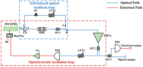
Figure 1.
The schematic diagram of the DM-DFBL self-delayed feedback with an optoelectronic oscillation loop. DM-DFBL: directly modulated distributed feedback semiconductor laser, Cir: optical circulator, ODL: optical delay line, OC: optical coupler, ATT: optical attenuator, PC: polarization controller, EDFA: erbium-doped fiber amplifier, PD: photodetector, EA: electrical amplifier.
Based on schematic diagrams and semiconductor rate equations [9,18], the rate equation for the optical and optoelectronic hybrid system can be expressed as follows:
where , , and represent the carrier number, photon number, and phase, respectively. The set of equations describes the carrier number, photon number, and phase in the laser as a function of time. is the optical feedback intensity, defined as the ratio of the injected power to the free-running power. is electrical feedback intensity that is a dimensionless feedback parameter, denoting the effect of the optoelectronic oscillation loop on nonlinear dynamic states. In addition, is the delay time of light in the optical feedback loop, and is the delay time of light in an optoelectronic feedback loop. This ensures that the system is long-delayed (the delay time is more than the relaxation oscillation time: 0.112 ns) and saves computer facilities. Besides, the output power of DM-DFBL can be expressed as follows:
All the parameters and corresponding values are listed in Table 1. The values are extracted from a typical semiconductor laser.

Table 1.
Simulation parameters, values, and symbol notations.
Equations (1)–(5) are solved numerically via the fourth-order Runge–Kutta algorithm. The time series and frequency spectrum of different dynamic states are obtained through numerical calculations. The bifurcation diagram of the dynamic states is obtained from successive extrema (maximum and minimum) of the amplitude in the time series when the optical feedback intensity takes different values. These results are used to analyze the dynamic behavior of the DM–DFBL.
Firstly, the dynamic states generated by the DM-DFBL self-delayed pure optical feedback are studied. The DM-DFBL exhibits the CO state, QP state, and P1 state with the decrease of optical feedback intensity, as shown in Figure 2. When , the time series are irregular waveforms with randomly varying peaks, and the frequency spectrum is continuous, as shown in Figure 2(a1,a2). These results indicate that the laser is in the CO state. Figure 2b demonstrates that, in the circumstance of , the time series manifests a tendency towards periodicity, but each cycle exhibits distinct characteristics. Moreover, the frequency spectrum displays numerous oscillation modes, as shown in Figure 2(b2). The intensity of these oscillation modes is found to be non-uniform, and the intervals between them are inconsistent. This indicates that the DM-DFBL is a QP state, which is an intermediate state between the chaotic and periodic states. When , the time series are strictly sinusoidal signals, and the frequency spectrum exhibits a high-power oscillation mode with a frequency of about 8.513 GHz. In addition, the lower power oscillation modes at 17.026 GHz and 25.539 GHz are also identified in Figure 2(c2), which are the higher-order modes of the P1 oscillation (a frequency-doubled signal and a frequency-triple signal). These results indicate that the laser is in the P1 state, which originates from the relaxation oscillations of the DM-DFBL. In order to more fully describe the distribution of the dynamical states of the DM-DFBL in parameter space, the bifurcation diagram is presented in Figure 3.
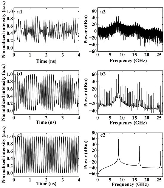
Figure 2.
The time series and the frequency spectrum of different dynamic states that are generated based on DM-DFBL self-delayed feedback: (a) CO, ; (b) QP, ; (c) P1, (1, 2 represent the time series and the frequency spectrum, respectively).
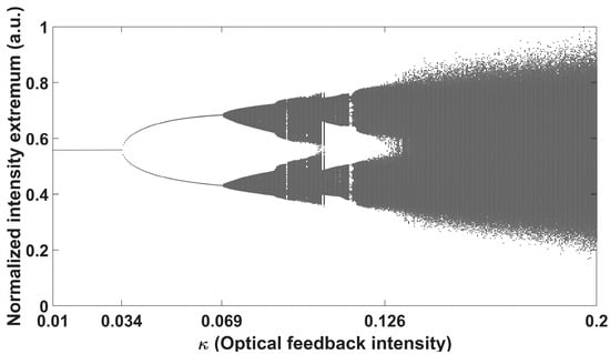
Figure 3.
The bifurcation diagram of the dynamics states that are generated based on DM-DFBL self-delayed pure optical feedback with the variation of .
Figure 3 shows the bifurcation diagram of the dynamics states that are generated based on DM-DFBL self-delayed pure optical feedback, with the variation of . When is smaller than 0.034, the feedback light is not enough to interfere with the output of the DM-DFBL; thus, the DM-DFBL is in a steady state. When is more than 0.034, there is a maximum or a minimum at the same position, indicating that the DM-DFBL is in the P1 state. Meanwhile, the intensity of the P1 state is enhanced with the increase of . When is more than 0.069, the feedback light interacts with the cavity mode to induce multiplicative period bifurcations, resulting in multiple extreme points at the same position. It means that DM-DFBL is in the MP state or QP state. There is an increase in the number of extreme points with an increase in . When is more than 0.126, the intense competition between individual modes in the laser can occur, the bifurcations quickly increase, and the periodicity of the DM-DFBL is destroyed. Eventually, the DM-DFBL evolves to the CO state. This evolutionary process is called multiplicative period bifurcation, which is a typical dynamic state evolutionary process.
The dynamic behaviors of the optoelectronic oscillation loop are studied, as shown in Figure 4. The optoelectronic oscillation loop can be considered as an OEO, which is a typical feedback system with rich nonlinear dynamic state characteristics. The rich dynamic behavior in the OEO benefits from the high-gain feedback. Figure 4a shows the results for . The time series presents a regular pulse signal, and there is a series of equally spaced frequency components with a frequency interval of 3.14 GHz in the frequency spectrum, i.e., the MFC. The MFC originates from the nonlinearity of the DM-DFBL because the injected electrical signal causes the laser to operate in the nonlinear region. Figure 4b shows the results for ; it is evident that some frequency components with a frequency interval of 244 MHz and relatively low intensity appear between the MFC frequency components in the spectrum. The frequency interval of these components is called the free spectral range (FSR, , where is the velocity of optical, is the effective refractive index of the transmission medium, is the length of the OEO loop). These FSRs originate from the OEO oscillation eigenmodes, which are determined by the length of the OEO loop (corresponding time delay is 4 ns) and the relaxation oscillation time of the DM-DFBL. Nevertheless, the time series maintains regular pulse signals due to the MFC’s dominant influence. Figure 4c shows the results for . The MFC has essentially disappeared, and a set of FSRs with a frequency interval of 244 MHz is observed in the frequency spectrum. It is named the full-frequency oscillation from a self-locking state of the fundamental frequency [19]. The regular pulse signal appears with burrs in the time series due to the spectrum components of the MFC still exists, as shown in Figure 4(c1,c2). Moreover, due to the well-defined phase relationships among spectral components in pulse signals, the optoelectronic oscillation loop contributes to enhanced signal stability in experimental systems.
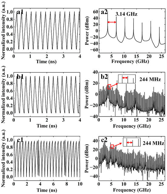
Figure 4.
The time series and the frequency spectrum of different dynamic states that are generated based on an optoelectronic oscillation loop: (a) ; (b) ; (c) (1, 2 represent the time series and the frequency spectrum, respectively).
From the above results, it is seen that both the time series and frequency spectrum are capable of representing the same dynamic state. In order to reduce the length of the article without compromising its generalisability, the frequency spectrum is uniformly used without any particular cases in the subsequent discussion.
Based on the above results, the mutual effect of DM-DFBL self-delayed feedback and optoelectronic oscillation loops on the dynamic states is further explored. At first, the output of the DM-DFBL self-delayed feedback is set to the CO state and then introduced into the optoelectronic oscillation loop. When and , although the frequency spectra are still continuous, the oscillation modes around 8.5 GHz are all enhanced to different degrees, as shown in Figure 5(a1,a2). When , some oscillation envelopes appear near direct current (DC), with the corresponding frequency interval is about 244 MHz, as shown in Figure 5(a3). This means that the optoelectronic oscillation loop is gradually dominating the output of the laser. But overall, the laser is still in the CO state, and the introduction of the optoelectronic oscillation loop enhances mode competition within the laser.
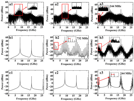
Figure 5.
The frequency spectrum of different dynamic states that are generated based on a hybrid architecture combining pure optical feedback and optoelectronic feedback under different values of : (a) The DM-DFBL self-delayed feedback primitive output is CO state; (b) The DM-DFBL self-delayed feedback primitive output is QP state; (c) The DM-DFBL self-delayed feedback primitive output is P1 state (1, 2 and 3 represent , and , respectively).
Next, the output of the DM-DFBL self-delayed feedback is set to the QP state and then introduced into the optoelectronic oscillation loop. In the case of , the dynamic state of the DM-DFBL is transferred from the original QP (Figure 2b) to the P1 state, as shown in Figure 5(b1). The phenomenon is caused by the vernier caliper effect of the two oscillating modes of the self-delayed feedback loop and the optoelectronic oscillation loop. The optoelectronic oscillation loop can drive the QP state into a periodic state, owing to the inherent susceptibility of QP states to external disturbances. When , a number of frequency components appear in the frequency spectrum, and the corresponding FSR is about 732 MHz (3 times the FSR of the OEO), which is also the MFC, as shown in Figure 5(b2). When , the periodic states in the frequency spectrum are destroyed, and the output of the laser develops towards the eigenoscillation of the OEO, as shown in Figure 5(b3). This means that the optoelectronic oscillation loop is gradually dominating the output of the laser.
Finally, the output of the DM-DFBL self-delayed feedback is set to the P1 state and then introduced into the optoelectronic oscillation loop. When and , the output of the DM-DFBL is still in the P1 state, as shown in Figure 5(c1,c2). There is no obvious change in the P1 state when compared to the case in the absence of the introduction of the optoelectronic oscillation loop (Figure 2c). It is due to the limitation of the accuracy of the fourth-order Runge–Kutta algorithm in the numerical calculation process. In a subsequent experiment, the enhancement of the P1 state is found to have an obvious effect. When , the oscillation mode with FSR = 244 MHz appears near DC, as shown in Figure 5(c3). Consequently, this is further evidence that the optoelectronic oscillation loop is gradually dominating the output of the laser.
3. Experimental Results and Discussion
The schematic diagram of the experiment is shown in Figure 1. The DM-DFBL (WAVE OPTICS DML-1550-20-10-FA, Beijing, China) without internal isolation is used, and its threshold current is 7 mA. In the experiment, the bias current of the DM-DFBL is set to 13 mA, and the DM-DFBL free-running optical power and wavelength are −0.42 dBm and 1547.68 nm, respectively, at an operating temperature of 25 °C. The PD (FINISAR XPDV2120R, bandwidth: 50 GHz, Saxonburg, PA, USA) converts the optical signal into an electrical signal, and the EA (SHF S126A, gain: 29 dB, Berlin, Germany) provides gain to the loop. In addition, the length of the fiber link for the self-delayed feedback loop is approximately 24 m, with a corresponding . The length of the fiber link for the optoelectronic oscillation loop is approximately 64 m, with a corresponding . The relaxation oscillation frequency of the DM-DFB is about 8.9 GHz, as shown in Figure 6c. Accordingly, the coupling delay of the self-delayed feedback loop and the optoelectronic oscillation loop is much larger than the relaxation oscillation time (1/8.9 GHz = 0.112 ns). Therefore, the self-delayed feedback and the optoelectronic oscillation are a long-delay system. The optical spectrum of the generated dynamic states is observed by an optical spectrum analyzer (YOKOGAWA AQ6370C, minimum resolution: 0.02 nm, Tokyo, Japan), and its frequency spectrum and waveforms are observed by an electrical spectrum analyzer (Agilent N9010A, frequency range: 9 kHz–26.5 GHz, Santa Clara, CA, USA), respectively.
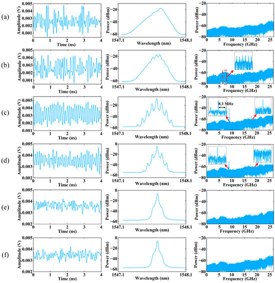
Figure 6.
The time series, the optical spectrum and the frequency spectrum of different dynamic states that are generated based on the DM-DFBL self-delayed pure optical feedback: (a) CO; (b) QP; (c) P1; (d) weak P1; (e) weak feedback; (f) free output; (first column: the time series; second column: the optical spectrum; third column: the frequency spectrum).
3.1. The Dynamic States Generated by the DM-DFBL Self-Delayed Feedback
Firstly, the DM-DFBL self-delaying feedback loop is in operates alone (connect point A and disconnect point B), as shown in Figure 1. The optical signal from point B was measured using an optical spectrum analyzer. After photoelectric conversion via a PD, the optical signal from point B was measured using an oscilloscope (for time series) and a spectrum analyzer (for frequency spectrum). Under optimal phase-polarization matching conditions, the laser exhibits rich dynamic states when the injection powers are changed by adjusting ATT1. The output of the DM-DFBL exhibits dynamic states, including CO state, QP state, P1 state, weak P1 state, and free state, with the decrease of , and the corresponding results are shown in Figure 6. These results are consistent with the trends observed in Figure 3 of the numerical calculations.
When , the time series are irregular waveforms with randomly varying peaks, as shown in Figure 6a. Compared to the optical spectrum of free output (Figure 6f), the single-mode feature of the output is broken, and the optical spectrum is broadened, and the frequency spectrum is a flat continuous spectrum. These results indicate that the laser is in a CO state. When , although the time series are still chaotic, the intervals between each peak seem to exhibit periodicity, as shown in Figure 6b. The optical spectrum narrows gradually and presents optical sidebands compared to the CO state. The corresponding frequency spectrum also narrows with the energy gradually concentrating, and a set of oscillatory envelopes appear at the concentration, as shown in the inset in Figure 6b. It means that the laser is in the QP state. When , the time series is not a strictly sinusoidal signal; it fluctuates in amplitude, as shown in Figure 6c. This is due to the fact that the P1 oscillation is formed by the dynamic competition between a regeneration mode and a cavity mode after redshift. The oscillation is more sensitive to external disturbances, resulting in an unstable generated P1 signal. Therefore, the amplitude of the sinusoidal has certain fluctuations while possessing a strict periodicity. The optical spectrum is centered on the cavity mode of the DM-DFBL with multiple optical sidebands of fixed wavelength differences. This is a typical optical spectrum of a P1 oscillation. The frequency spectrum has a high-power oscillation mode with a frequency of approximately 8.9 GHz, and an oscillation mode of lower power is also found at 17.8 GHz, which is a higher-order mode of the P1 oscillation (a frequency-doubled signal). These results indicate that the laser is in the P1 state. When , the amplitude of the time series, optical spectrum, and frequency spectrum is all weakened, as shown in Figure 6d. In addition, the number of optical sidebands decreases in the optical spectrum, and higher-order modes disappear in the frequency spectrum, but the general trend is consistent with the P1 state. These results indicate that the laser is in the weak P1 state. When , the corresponding time series, optical spectrum, frequency spectrum, and free outputs of the DM-DFBL are almost consistent, as shown in Figure 6e,f. This means that the injected light almost has no influence on the output of the laser.
3.2. The Dynamic States Generated by the Optoelectronic Oscillation Loop
The optoelectronic oscillation loop is in operates alone (disconnect point A and connect point B), as shown in Figure 1. In the experiment, the electrical feedback intensity () is expressed in terms of the power injected into PD1. When , the optical signal is converted into an electrical signal with weak intensity. However, the inherent high gain of the EA amplifies even weak electrical signals beyond the oscillation threshold, initiating sustained oscillations. In this experiment, the non-flat open-loop response of the OEO (manifested through frequency-dependent EA gain variations) creates preferential amplification conditions, and the shorter fiber length in the OEO loop results in an extended FSR of 3.1 MHz, thus partially suppressing conventional multi-mode oscillations. Under these combined effects, a specific oscillatory mode coinciding with the EA’s optimal response frequency becomes dominant [19]. Through iterative feedback modulation, this selected mode undergoes progressive enhancement, ultimately evolving into a stabilized single-mode microwave signal as shown in Enlarged view 1 of Figure 7a. The frequency spectrum profile confirms the OEO’s operation in the fundamental P1 oscillation regime. Additionally, the system simultaneously generates the frequency-doubled harmonic component observable in the Enlarged view 2 of Figure 7a, indicative of nonlinear interactions within the oscillation dynamics. It is noteworthy that the P1 does not appear since the open-loop response of the OEO is flat in the numerical calculations. When , there is a series of equally spaced frequency components with a frequency interval of 123.8 MHz, i.e., the MFC, as shown in Figure 7b. In the Enlarged view 2 of Figure 7b, there is no obvious FSR, indicating that the system has not yet reached the oscillation threshold. In fact, the intensity of these MFC’s frequency components is enhanced and the number of frequency components is increased when they can get more gain. When , there is a series of FSRs with a frequency interval of 3.1 MHz generated, as shown in Figure 7c. It means that the loop starts to oscillate due to thermal noise.
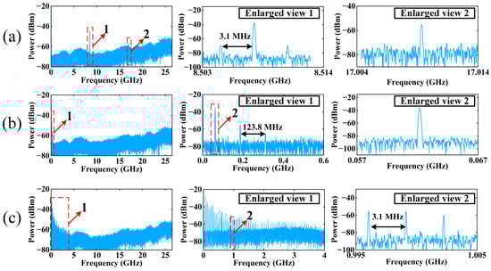
Figure 7.
The frequency spectrum of different dynamic states that are generated based on the optoelectronic oscillation loop: (a) ; (b) ; (c) ; (Enlarged view 1 and 2 are enlarged views of parts of 1 and 2, respectively).
3.3. The Dynamic State Generated by DM-DFBL Self-Delayed Feedback with an Optoelectronic Oscillation Loop
In order to study the mutual effect of the DM-DFBL self-delayed feedback and the optoelectronic oscillation loops on the dynamic state, connect points A and B, as shown in Figure 1. At first, the output of the DM-DFBL self-delayed feedback is set to the CO state and then introduced into the optoelectronic oscillation loop, as shown in Figure 8a. When , although the frequency spectrum is still a relatively flat continuous spectrum, there is a certain concentration of energy around 6.35 GHz. Meanwhile, a series of oscillatory envelopes can be observed, as shown in Figure 8(a1). This is due to the fact that the injection of electrical signals in the electrical feedback loop changes the concentration of carriers in the DM-DFBL, and thus, the output of the laser is disturbed. When , some frequency components appear near DC with the corresponding frequency interval is 123.8 MHz, as shown in Figure 8(a2). This is consistent with the characteristics of the optoelectronic oscillation loop when operating alone, as shown in Enlarged view 1 of Figure 7b. It means that the optoelectronic oscillation loop is gradually dominating the output of the laser. When , the full-frequency oscillation is observed in Figure 8(a3). It reveals that the optoelectronic oscillation loop is completely dominant, i.e., the optoelectronic oscillation loop changes the original output state of the DM-DFBL self-delayed feedback. In conclusion, the optical and optoelectronic hybrid loops can directly affect the original output state and change the evolution of the dynamic state of the laser. For further validation, the following analysis continues to study the changes in the QP state and P1 state.
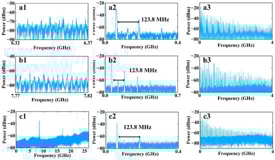
Figure 8.
The frequency spectrum of different dynamic states that are generated based on DM-DFBL self-delayed feedback with an optoelectronic oscillation loop under different values of : (a) the DM-DFBL self-delayed feedback primitive output is CO state; (b) the DM-DFBL self-delayed feedback primitive output is QP state; (c) the DM-DFBL self-delayed feedback primitive output is P1 state (1, 2 and 3 represent , and , respectively).
Next, the output of the DM-DFBL self-delayed feedback is set to the QP state and then introduced into the optoelectronic oscillation loop, as shown in Figure 8b. When , the concentration of energy in the frequency spectrum is more obvious compared to Figure 6b, as shown in Figure 8(b1). It means that the optoelectronic oscillation loop has enhanced the oscillatory state of the QP state. When , the variation trend of the dynamic state is consistent with the original output of the DM-DFBL in the CO state. The optoelectronic oscillation loop gradually dominates, as shown in Figure 8(b2). When , the full-frequency oscillation is also observed in Figure 8(b3). It also reveals that the optoelectronic oscillation loop is completely dominant in the output of the laser.
Finally, the output of the DM-DFBL self-delayed feedback is set to the P1 state and then introduced into the optoelectronic oscillation loop, as shown in Figure 8c. When , the intensity and stability of the P1 state and the frequency-doubling signal are enhanced, as shown in Figure 8(c1). This is due to the fact that the DM-DFBL self-delayed feedback and the optoelectronic oscillation loop can generate a P1 state independently. When the polarization and phase of the two loops are matched to an optimal state by adjusting PC and ODL, one of the P1 signals can lock the other. Ultimately, the stability of the P1 can be enhanced. When and , the variation trend of the dynamic state is consistent with the original output of the DM-DFBL in the CO state, as shown in Figure 8(c2,c3). These results are generally consistent with the trends observed in Figure 5 of the numerical calculations.
4. Conclusions
In conclusion, through numerical simulations and experimental validation, we systematically investigated the nonlinear dynamical evolution of a distributed feedback laser diode (DM-DFBL) under three configurations: standalone self-delayed optical feedback, optoelectronic oscillation (OEO) loops, and hybrid optical-electronic feedback systems. The numerical simulations and experimental results reveal the characteristics of the DM-DFBL’s nonlinear evolution. The dynamical state of DM-DFBL evolves a path from the CO state to the periodic state and the steady state in the self-delayed feedback loop as a decrease of optical feedback intensity. The DM-DFBL generates the MFC and the full-frequency oscillation in the optoelectronic oscillation loop as a variation of electrical feedback intensity. By introducing the optoelectronic oscillation loop, the dynamic state of DM-DFBL self-delayed feedback can be disturbed, and the optoelectronic oscillation loop gradually dominates as the electrical feedback intensity increases. It can also enhance the QP state and the P1 state when the output of the DM-DFBL is QP state and P1 state. In addition, the DM-DFBL also presents the P1 state due to the non-flat open-loop response of the OEO in the experiment. The study of these dynamic characteristics has helped to understand the mechanisms that generate dynamical states and also extended the application of microwave signals.
Author Contributions
Conceptualization, N.X. and G.B.; data curation, S.X. and D.H.; formal analysis, N.X. and X.W.; funding acquisition, G.B.; investigation, N.X. and Q.W.; methodology, N.X. and G.B.; project administration, G.B.; resources, G.B.; software, N.X. and Y.L.; supervision, G.B. and W.H.; validation, N.X., G.B., and G.K.; visualization, N.X.; writing—original draft, N.X.; writing—review & editing, G.B. All authors have read and agreed to the published version of the manuscript.
Funding
This work is supported in part by the Scientific and Technological Project of Guizhou Province (Grant Numbers: QianKeHeJiChu-ZK [2024]-KeyProject-001), in part by the National Key Research and Development Program of China (2021YFB2206300), in part by the National Natural Science Foundation of China (Grant Numbers: 61965004), and in part by the introduction talent research start-up fund of Guizhou University (Guida Ren Ji He Zi [2018-14]).
Institutional Review Board Statement
Not applicable.
Informed Consent Statement
Not applicable.
Data Availability Statement
Data will be made available on request.
Conflicts of Interest
The authors declare no conflicts of interest.
References
- Schires, K.; Hurtado, A.; Henning, I.D.; Adams, M.J. Comprehensive experimental analysis of nonlinear dynamics in an optically-injected semiconductor laser. AIP Adv. 2011, 1, 32131. [Google Scholar] [CrossRef]
- Kong, H.J.; Wu, Z.M.; Wu, J.G.; Xie, Y.K.; Lin, X.D.; Xia, G.Q. Experimental observations on the nonlinear behaviors of DFB semiconductor lasers under external optical injection. Chaos Solitons Fractals 2008, 36, 18–24. [Google Scholar] [CrossRef]
- Yao, J.P.; Capmany, J. Microwave photonics. Sci. China Inf. Sci. 2022, 65, 221401. [Google Scholar] [CrossRef]
- Zhou, P.; Li, N.Q.; Pan, S.L. Period-One Laser Dynamics for Photonic Microwave Signal Generation and Applications. Photonics 2022, 9, 227. [Google Scholar] [CrossRef]
- Luo, H.; Jiang, Y.; Dong, R.Y.; Tian, J.; Zi, Y.J.; Liu, H.F.; Wei, C.; Wang, R. Tunable single-mode microwave signal generation utilizing an all-optical coupled microwave oscillator. Opt. Express 2019, 27, 25829–25840. [Google Scholar] [CrossRef]
- Tistomo, A.S.; Gee, D.S. Laser frequency fixation by multimode optical injection locking. Opt. Express 2011, 19, 1081–1090. [Google Scholar] [CrossRef]
- Simpson, T.B.; Liu, J.M.; Huang, K.F.; Tai, K. Nonlinear dynamics induced by external optical injection in semiconductor lasers. Quantum Semiclassical Opt. J. Eur. Opt. Soc. Part B 1997, 9, 765. [Google Scholar] [CrossRef]
- Tang, J.; Bai, G.F.; He, Y.P.; Zhang, W.R.; Jiang, Y.; Xie, N.; Li, Y.F.; Kuang, G.; Cao, C.Q. Experimental Research on Dynamic Characteristics of Mutual Optical Injection Semiconductor Lasers with Long Delay. J. Light. Technol. 2025, 43, 3366–3375. [Google Scholar] [CrossRef]
- Cao, L.P.; Deng, T.; Lin, X.D.; Wu, J.G.; Xia, G.Q.; Wu, Z.M. Investigation on Nonlinear Dynamic Behaviors of the Distributed Feedback Semiconductor Laser Subjected to Optical Feedback. Chin. J. Lasers 2010, 37, 939–943. [Google Scholar]
- Lin, F.Y.; Liu, J.M. Nonlinear dynamics of a semiconductor laser with delayed negative optoelectronic feedback. IEEE J. Quantum Electron. 2003, 39, 562–568. [Google Scholar] [CrossRef]
- Chan, S.-C.; Hwang, S.-K.; Liu, J.M. Period-one oscillation for photonic microwave transmission using an optically injected semiconductor laser. Opt. Express 2007, 15, 14921–14935. [Google Scholar] [CrossRef] [PubMed]
- Tang, J.; Bai, G.F.; Tang, Y.L.; Xu, L.; Wang, G.X.; Shang, D.S.; Jiang, Y. All-optical microwave oscillator based on a mutual-injection coupling between DFB-LDs. Opt. Express 2022, 30, 42168–42177. [Google Scholar] [CrossRef] [PubMed]
- Choi, D.; Wishon, M.J.; Chang, C.Y.; Citrin, D.S.; Locquet, A. Multistate intermittency on the route to chaos of a semiconductor laser subjected to optical feedback from a long external cavity. Chaos Interdiscip. J. Nonlinear Sci. 2018, 28, 011102. [Google Scholar] [CrossRef] [PubMed]
- Bosco, A.K.D.; Ohara, S.; Sato, N.; Akizawa, Y.; Uchida, A.; Harayama, T.; Inubushi, M. Dynamics Versus Feedback Delay Time in Photonic Integrated Circuits: Mapping the Short Cavity Regime. IEEE Photonics J. 2017, 9, 1–12. [Google Scholar]
- Zhong, Z.Q.; Chang, D.; Jin, W.; Lee, M.W.; Wang, A.B.; Jiang, S.; He, J.X.; Tang, J.M.; Hong, Y.H. Intermittent dynamical state switching in discrete-mode semiconductor lasers subject to optical feedback. Photonics Res. 2021, 9, 1336. [Google Scholar] [CrossRef]
- Turovets, S.I.; Dellunde, J.; Shore, K.A. Nonlinear dynamics of a laser diode subjected to both optical and electronic feedback. J. Opt. Soc. Am. B 1997, 14, 200–208. [Google Scholar] [CrossRef]
- Chen, G.C.; Lu, D.; Liang, S.; Guo, L.; Zhao, W.; Huang, Y.G.; Zhao, L.J. Frequency-tunable Optoelectronic Oscillator With Synchronized Dual-Wavelength Narrow-Linewidth Laser Output. IEEE Access 2018, 6, 69224–69229. [Google Scholar] [CrossRef]
- Tang, S.; Liu, J.M. Chaotic pulsing and quasi-periodic route to chaos in a semiconductor laser with delayed opto-electronic feedback. IEEE J. Quantum Electron. 2001, 37, 329–336. [Google Scholar] [CrossRef]
- Chen, H.; Shen, Q.Y.; Xie, T.T.; Liu, S.F.; Yu, Q.Y.; Wang, Y.; Fu, H.Y.; Chen, D.R.; Xu, Z.Y.; Pan, S.L. Generation of Microwave Frequency Comb, Chaotic, and Single-Frequency Microwave Signal in a Short-Cavity-Based Optoelectronic Oscillator. J. Light. Technol. 2024, 42, 8102–8108. [Google Scholar] [CrossRef]
Disclaimer/Publisher’s Note: The statements, opinions and data contained in all publications are solely those of the individual author(s) and contributor(s) and not of MDPI and/or the editor(s). MDPI and/or the editor(s) disclaim responsibility for any injury to people or property resulting from any ideas, methods, instructions or products referred to in the content. |
© 2025 by the authors. Licensee MDPI, Basel, Switzerland. This article is an open access article distributed under the terms and conditions of the Creative Commons Attribution (CC BY) license (https://creativecommons.org/licenses/by/4.0/).