Article

Efficient Generation of Transversely and Longitudinally Truncated Chirped Gaussian Laser Pulses for Application in High-Brightness Photoinjectors

Deutsches Elektronen-Synchrotron DESY, Platanenallee 6, 15738 Zeuthen, Germany
*
Author to whom correspondence should be addressed.
These authors contributed equally to this work.
Photonics 2025, 12(5), 460; https://doi.org/10.3390/photonics12050460
Submission received: 31 March 2025 / Revised: 3 May 2025 / Accepted: 7 May 2025 / Published: 9 May 2025
(This article belongs to the Special Issue Photonics: 10th Anniversary)

Abstract

:
The optimization of photoinjector brightness is crucial for achieving the highest performance at X-ray free-electron lasers. To this end, photocathode laser pulse shaping has been identified as a key technology for enhancing photon flux and lasing efficiency at short wavelengths. Supported by beam dynamics simulations, we identify transversely and longitudinally truncated Gaussian electron bunches as a beneficial bunch shape in terms of the projected emittance and 5D brightness. The realization of such pulses from chirped Gaussian pulses is studied for 514 nm and 257 nm wavelengths by inserting an amplitude mask in the symmetry plane of the pulse stretcher to achieve longitudinal shaping and an aperture for transverse beam shaping. Using this scheme, transversely and longitudinally truncated Gaussian pulses can be generated and later used for the production of up to 3 nC electron bunches in the photoinjector. The 3D pulse shape at a wavelength of 514 nm is characterized via imaging spectroscopy, and second-harmonic generation frequency-resolved optical gating (SHG FROG) measurements are also performed to analyze the shaping scheme’s efficacy. Furthermore, this pulse-shaping scheme is transferred to a UV stretcher, allowing for direct application of the shaped pulses to cesium telluride photocathodes.

1. Introduction

The availability of a high-brightness electron source is a critical factor for ensuring the optimal performance and successful operation of linear accelerator-based free-electron lasers (FELs). The main goal in the research of photoinjectors for X-ray FELs is to maximize the driving electron bunch brightness
B = Q ϵ n , x ϵ n , y ϵ n , z
by maximizing the generated charge Q and minimizing the 6D phase space volume, which is represented by the normalized RMS emittances ϵ n . The overall transverse emittance ϵ t o t a l has several contributions, which can be grouped as being related to the cathode ϵ C a t h , the RF fields ϵ R F , and the surrounding magnets as the solenoid magnet ϵ s o l , as well as remaining magnetic field components at the surface of the cathode introduced by the solenoid magnet ϵ B z , c a t h (cf. [1,2,3]):
ϵ t o t a l = ϵ C a t h 2 + ϵ R F 2 + ϵ S C 2 + ϵ s o l 2 + ϵ B z , c a t h 2 .
The previously listed terms can be minimized by maximizing the applied RF field, cathode material, and surface quality, as well as the applied magnetic field. The space charge contribution ϵ S C can be controlled by laser pulse shaping. Depending on the laser pulse shape, the brightness of the generated electron bunch can be improved by a factor of 2 to 4, making pulse shaping for photoinjectors an active field of research. However, in operation at FEL facilities, lasers for photoinjectors usually have Gaussian profiles as transverse beam profiles and in the spectral and temporal domains. Depending on the photocathode material, NIR lasers are converted to their second, third, or fourth harmonic. Pulse-shaping schemes are commonly available for infrared lasers and subsequent conversion of the desired shape to the necessary photon energy for overcoming the binding energy of the cathode material.
The ideal electron bunch distribution for minimized emittance is the uniformly filled 3D ellipsoid, which exhibits space-charge fields with a linear dependence on the position within the distribution [4,5,6,7]. This distribution is immune to phase-space dilution due to space charge. The first scheme for generating such a distribution using photoemission electron sources was proposed by Serafini [8] and subsequently refined by Luiten et al. [9] utilizing femtosecond laser pulses impinging on a fast photoemitter in a strong accelerating electric field, operating within the “blow-out regime” where linear space-charge forces dominate. However, this regime has drawbacks for photoinjectors of X-ray free-electron lasers in terms of balancing a high charge and good emittance.
For an L-Band photoinjector operating at 1.3 GHz, e.g., at the Photo Injector Test Facility at DESY in Zeuthen (PITZ), the optimal pulse duration of the laser pulses should be close to ∼20 ps (∼10° of the RF phase) to achieve high peak brightness. To simultaneously achieve high average brightness, multi-MHz repetition rates of the laser are required. This has been achieved through the fourth harmonic generation of Nd-doped [10] and Yb-doped solid-state lasers [11], as well as the recent development of fiber lasers [12]. However, their narrow spectral bandwidths limit their pulse durations to a range of 0.25–5 ps. The implementation of pulse-shaping schemes with such lasers is challenging due to their inherent spectral characteristics and gain narrowing effects in the amplifier stages, which complicate the straightforward use of spatial light modulator-based configurations. Furthermore, generating and characterizing a 3D ellipsoidal distribution is particularly difficult, as it requires coupled control over the transverse and longitudinal components. This challenge extends to conventional pulse characterization methods that integrate only one component of the distribution, as well as many diagnostic techniques employed in accelerator facilities.
The first 3D ellipsoidal pulse shapes from Yb-doped solid-state lasers were realized by Mironov et al. using chirped pulses and LCOS SLMs (liquid crystal on silicon spatial light modulators) in a zero-dispersion grating stretcher configuration [13]. This experiment established the basis for the method of shaping chirped pulses for Yb-doped lasers and the diagnostics for 3D reconstruction. Bandwidth-limited laser pulses are stretched to maintain a nearly linear relation between the frequency and temporal domains, enabling spectral shaping that directly translates into the temporal pulse structure. These pulses facilitate the implementation of the slit-scan technique using a 2D spectrograph to assess their 3D shape. This scheme has been set up at PITZ and has undergone recent upgrades [14].
However, when realizing pulse shaping in the IR regime, a two-step frequency conversion to green and then UV is necessary, which can be prone to instabilities while aiming for high conversion efficiencies. To decrease susceptibility to instabilities caused by the fourth harmonic generation of Yb-doped lasers, our group investigated a 3D pulse-shaping scheme for a 514 nm wavelength [15,16], which has the advantages of being directly applicable to alkali antimonide photocathodes [17,18] and requiring only second harmonic generation for C s 2 Te photocathodes.
Although Gaussian pulses are commonly employed to drive photoinjectors at X-ray FELs today, our research focuses on the potential benefits of using 3D ellipsoidal pulses for future upgrades, e.g., continuous-wave operation with reduced gun gradients [19,20]. However, the applied technique of 3D amplitude shaping is associated with high losses, and the UV converted pulses can generate at most 500 pC using our scheme. Certain applications at PITZ need up to a 3 nC bunch charge, which requires modification of the pulse-shaping scheme. One way to achieve higher efficiency for the pulse-shaping scheme is to avoid downstream amplitude shaping with the associated losses and realize a simple amplitude mask directly while chirping the pulse to its final duration for the photoinjector. Due to its relatively simple realization, the idea of truncated Gaussian pulses is popular in ultrafast science for molecular alignment [21], material conditioning [22], and wave-packet dynamics for high harmonic generation [23,24]. Propagation effects for truncated Gaussian beams have been studied [25,26]. Also, for photocathode lasers, there are benefits of truncating the spatial profile, which is used for the generation of photoelectrons. The analytical prediction of an optimum truncation at 0.9 of the RMS width σ [27,28] has been realized at PITZ, showing a 15% reduction in the projected emittance for 250 pC [29]. Truncation by masks can also be used directly in the accelerator, e.g., in bunch compressors [30], or in the generation of trains of electron microbunches with adjustable subpicosecond spacing [31].
Here, we investigate the truncation of chirped Gaussian pulses in the spectral domain (Figure 1). By achieving a linear relationship between the spectral and temporal domains through chirping using a grating stretcher, it becomes possible to achieve temporally truncated Gaussian pulses. A combination of temporal and spatial truncations of the chirped laser pulses allows controlling all three dimensions of the laser pulses for photoelectron generation at the cathode of the RF gun.
Our approach offers a simple method for approximating truncated chirped Gaussian pulses by inserting a slit mask into the symmetry plane of a pulse stretcher. This method can be transferred to any CPA-based photocathode laser system in the pulse compressor, thus paving the way for studying 3D truncated Gaussian pulses in high-brightness photoinjectors. Section 2 provides an overview of the PITZ accelerator, the photocathode laser system, the application of amplitude masks in the pulse stretcher, and the characterization methods used for shaped pulses. Beam dynamics simulations and experiments at 514 nm and 257 nm are presented in Section 3, followed by a discussion in Section 4.

2. Materials and Methods
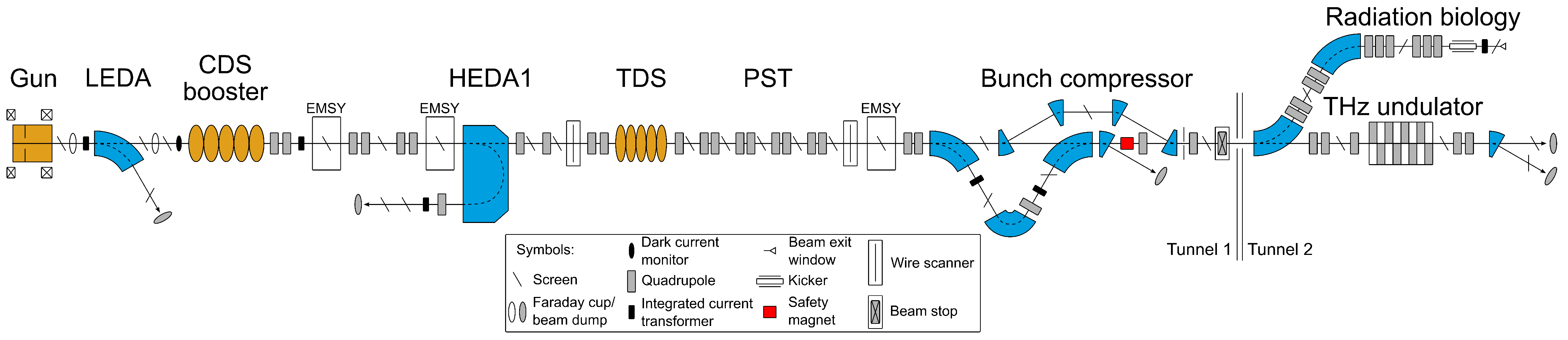
2.1. PITZ Overview

The Photo Injector Test Facility at DESY in Zeuthen (PITZ) serves as a dedicated research and development platform for RF photoinjectors and related technologies (Figure 2). Established over two decades ago, PITZ was initially designed to demonstrate electron source requirements for the Free-electron LASer in Hamburg (FLASH) [32,33] and the European XFEL [34,35]. The facility’s accelerator comprises a radio frequency (RF) photo gun and an RF booster cavity, with both standing wave resonators operating at 1.3 GHz and powered by two separate 10 MW klystrons. The RF gun features a nominal peak electric field of 60 MV/m at the cathode and a high quantum efficiency C s 2 Te photocathode with QE values ranging from 5 to 10%. This configuration enables the production of electron bunches with a maximum mean momentum of 6.5 MeV/c, which can be further accelerated to up to 23 MeV/c via the booster cavity. The RF systems and photocathode lasers operate at a repetition rate of 10 Hz (macropulse structure) with a duration of up to 850 µs, comprising micropulses at frequencies of either 1 MHz or 4.5 MHz, depending on the laser system employed. PITZ features electron beam manipulation and diagnostic capabilities, including quadrupole magnets, scintillator screens, emittance measurement systems (EMSY), beam position monitors, and charge measurement instruments, as well as a transverse deflecting structure (TDS) for longitudinal bunch profile measurements [36]. The TDS employs an electromagnetic field perpendicular to the electron bunch propagation direction, encoding the bunch’s spatial distribution onto a view screen in the phase space tomography section (PST) in a manner analogous to streak cameras.
The PITZ beamline has undergone continuous evolution to meet the research demands for the European XFEL, focusing on three primary objectives: developing, conditioning, and characterizing RF guns for both the FLASH and European XFEL. A key development goal is to enhance the electron bunch production rate from 27,000 to 45,000 per second, achievable through the introduction of a new gun type [37]. Concurrently, research efforts are underway to advance cathode technology, with ongoing tests on novel green photocathodes that promise simplified laser systems by eliminating the need for UV conversion [18]. Furthermore, these green wavelengths enable direct pulse-shaping schemes, which cannot be achieved in the UV due to high absorption or narrow spectral bandwidth. The beamline’s second segment is dedicated to applications, leveraging PITZ’s high-brightness electron source and diagnostics capabilities. Specifically, this includes operating a THz SASE FEL [38] and investigating radiation biology with ultra-high dose rates in an auxiliary beamline currently under development [39]. Both applications necessitate up to 3 nC electron bunch charges with low emittance. To investigate and optimize the experimental conditions of PITZ, simulations with particle tracers for specific scenarios are routinely performed [40,41,42].

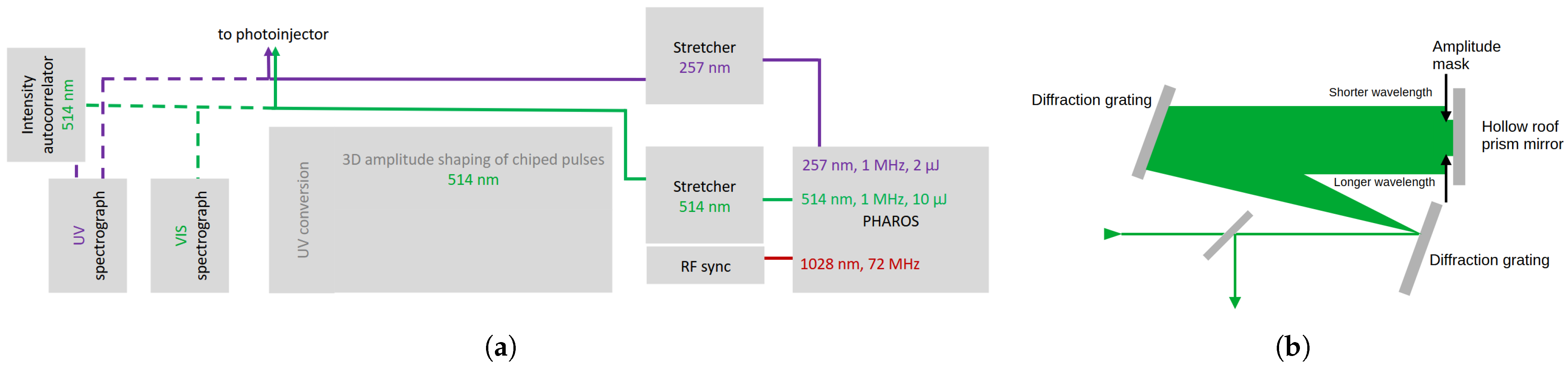
2.2. Laser System and Pulse-Shaping Scheme

Pulse shaping for the emittance optimization of the electron bunch is investigated using a commercial Yb:KGW CPA system (Light Conversion PHAROS, Vilnius, Lithuania). This laser system allows for synchronization with the 1.3 GHz frequency of the master oscillator through closed-loop oscillator-length control. The laser system is equipped with an internal frequency conversion unit, which enables the use of high power outputs with a 1 MHz repetition rate for 1028 nm, 514 nm, and 257 nm wavelengths. The bandwidth-limited output pulses have a duration of 260 fs, and their pulse energy is up to 20 µJ, 10 µJ, or 2 µJ, depending on the wavelength. The green laser pulses enter a grating stretcher to achieve linearly chirped pulses with a duration of 15 ps, and they were previously used for 3D amplitude shaping to generate ellipsoidal pulses [16] (Figure 3a).
The implementation of LCOS SLM-based amplitude shaping for generating 3D ellipsoidal pulses is accompanied by heavy losses of the input beam pulse energy. In addition, frequency conversion to UV is difficult to achieve while maintaining high conversion efficiency and good pulse-shape preservation, which limits this approach to charge levels of 500 pC at best from C s 2 Te photo cathodes, fitting the needs of the European XFEL.
However, a THz SASE FEL and radiation biology require several nC bunch charges, which cannot be achieved with the PHAROS system and 3D amplitude shaping of the chirped pulses at 514 nm. Thus, the amplitude mask is incorporated into the symmetry plane of the pulse stretcher. At this position, the spectrum of the laser pulse is spatially separated and can be cut to achieve a spectrally truncated Gaussian distribution (Figure 3b). The same scheme can be applied to UV pulses by applying the technique to a UV stretcher. The beam profile of the laser pulse can be controlled by adjusting the beam size and the iris diameter of the beam-shaping aperture, which is then imaged to the photocathode.
The chirping of the bandwidth-limited laser pulses is introduced by grating stretchers at 514 nm and 257 nm, which introduce negative group delay dispersion. For 514 nm, a transmission grating (PCG-3039/450-810, Ibsen Photonics, Farum, Denmark) and horizontal and vertical hollow roof prism mirrors are used to introduce ∼−1,300,000 fs². In total, four passes over the grating lead to a transmission of ∼40%. For 257 nm, a high-performance transmission grating (PCG 3846 l/mm, >93% UV transmission, Jenoptik AG, Jena, Germany) is used with 5 high-reflective-coated hollow roof prism mirrors to achieve 8 passes over the grating to introduce ∼−900,000 fs² with a total transmission of ∼60%. Further details on the pulse stretching and amplitude masking can be found in Appendix A.

2.3. Beam Transport to the Photocathode
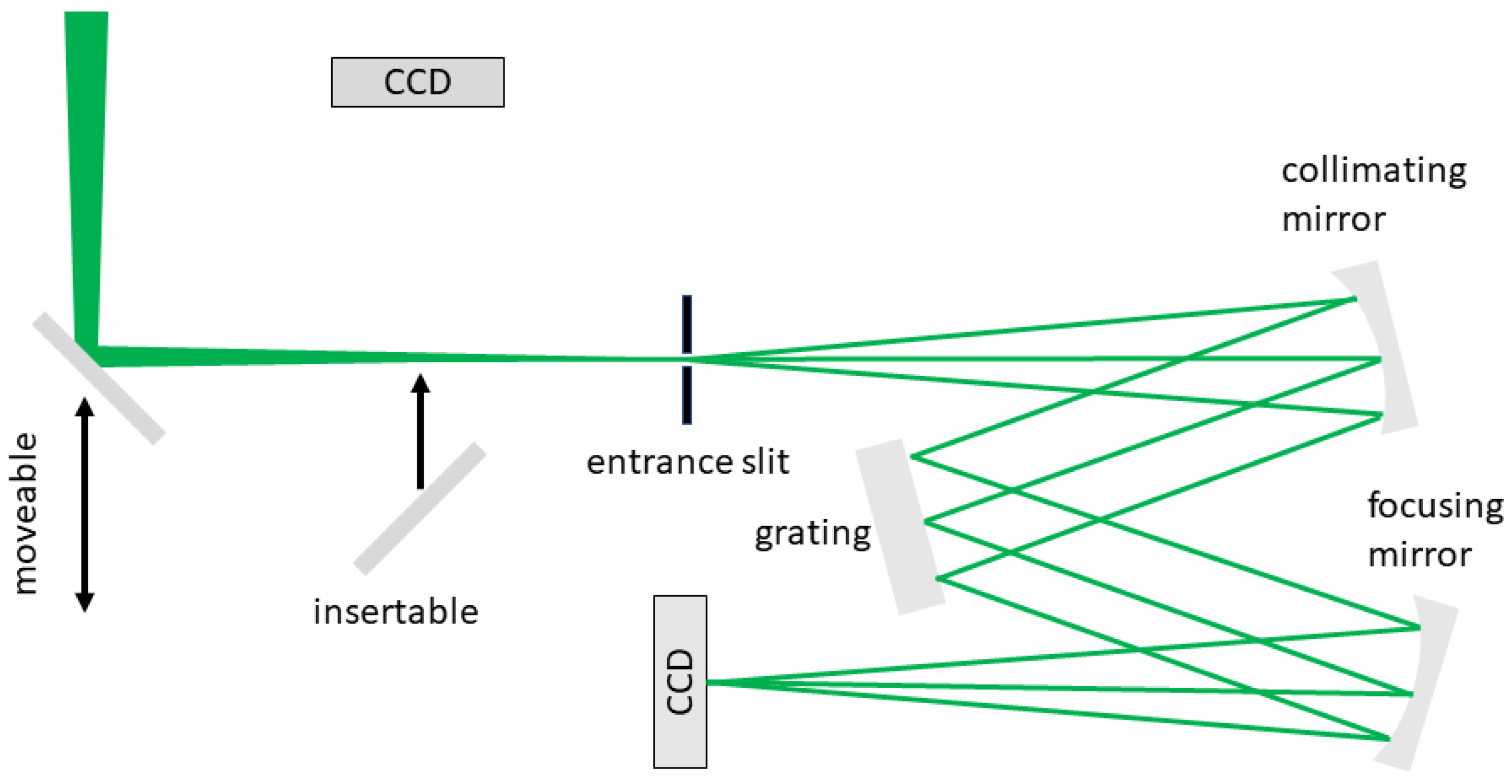
The distance between the laser output and the photocathode in the RF gun is approximately 45 m. This distance is divided into multiple relays to achieve high beam stability via imaging on the photocathode. The whole beamline is equipped with dual-band optics, which are coated for 515 nm and 257 nm wavelengths, to support the investigation of alkali antimonide and C s 2 Te photocathodes. Before entering the beamline to the photocathode, a variable beam attenuator based on a half-wave plate and two Brewster plates is installed to adjust the charge of the electron bunch. A 4-f imaging system (l = 13,000 mm) with variable magnification at the exit of the laser table allows for the adjustment of the beam diameter to the experimental demands of the accelerator and to image onto the beam-shaping aperture (BSA). Another 4-f imaging system (1:1, l = 22,000 mm) images the BSA onto the photocathode.

2.4. Diagnostics

The 3D reconstruction of chirped pulses is achieved using the so-called slit-scan technique [13]. For such a measurement, a high-resolution Czerny–Turner 2D imaging spectrograph is utilized, and the chirped pulse is scanned over the slit by a movable mirror. A slit-scan setup has been realized for green and UV wavelengths [16] (Figure 4). The detectors in the 2D imaging spectrographs are a Prosilica GC 1350 (Allied Vision, Stadtroda, Germany, 1060 × 1024 pixels, 7.2 pm spectral resolution) for 514 nm and a CM-140-GE-UV (JAI, Copenhagen, Denmark, 1392 × 1040 pixels, 6.5 pm spectral resolution) for 257 nm.
Besides spectral characterization using slit-scan measurements and assuming a linear relationship between the spectral and temporal domains by predominantly introducing group delay dispersion using a grating stretcher, temporal pulse shape characterization is performed using SHG FROG [43], which is a standard measurement technique for ultrashort laser pulses in the femtosecond and picosecond regimes. FROG measurements allow for the iterative reconstruction of the electric field of the laser pulse. However, SHG FROG can only be applied to IR and green laser pulses, but not to UV laser pulses, due to the strong absorption of the resulting wavelength. For UV pulses, characterization using non-frequency converting techniques, such as polarization-gate (PG), self-diffraction (SD), or transient-grating (TG) FROG techniques, is, in principle, possible [44]. Another advantage of these χ ( 3 ) -based FROG implementations is the ability to distinguish the temporal delay direction for the measurement. An χ ( 2 ) -based measurement is symmetric in the temporal domain; therefore, the leading and trailing edges of the pulse cannot be distinguished by SHG FROG, while the experimental implementation is much simpler.

3. Results

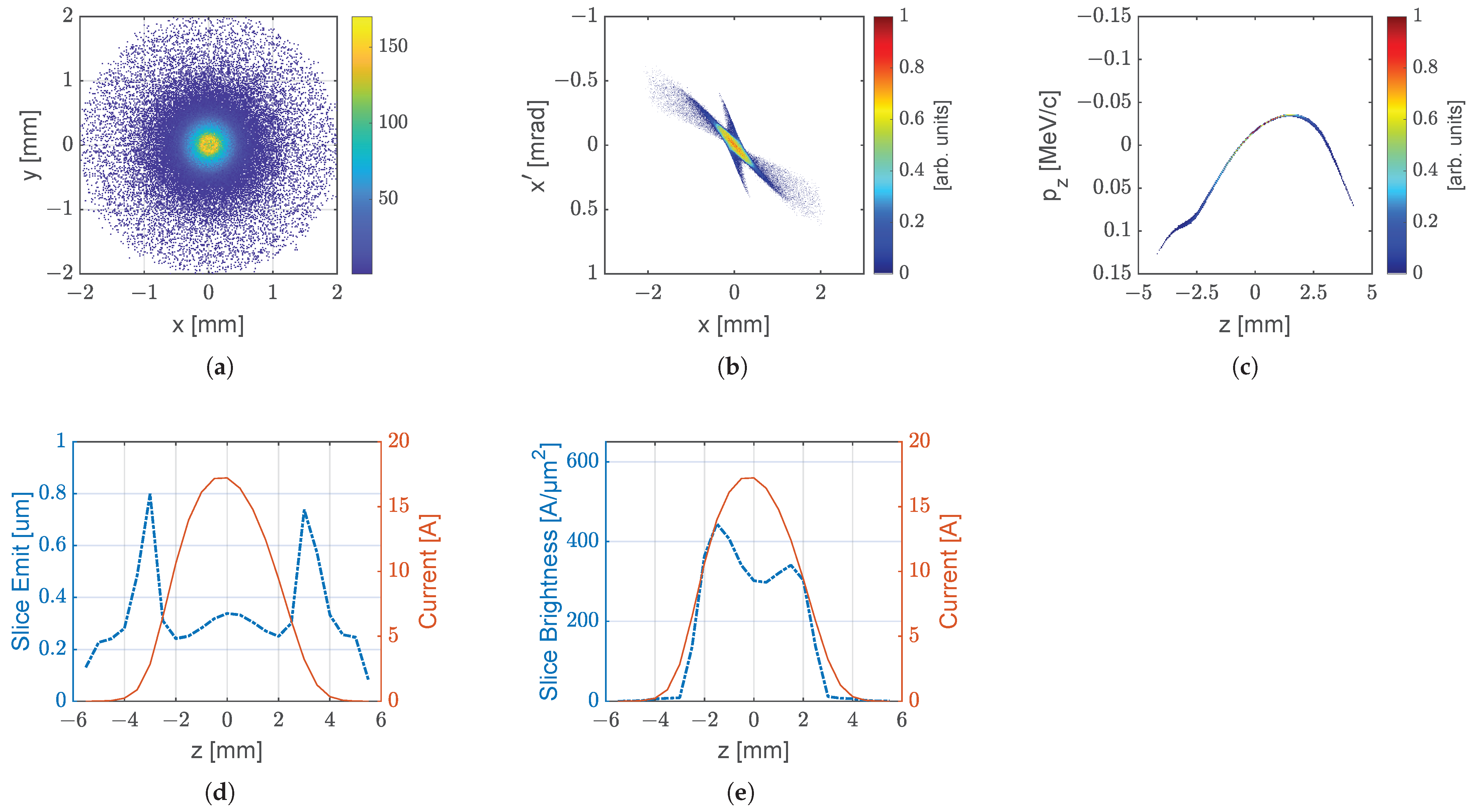
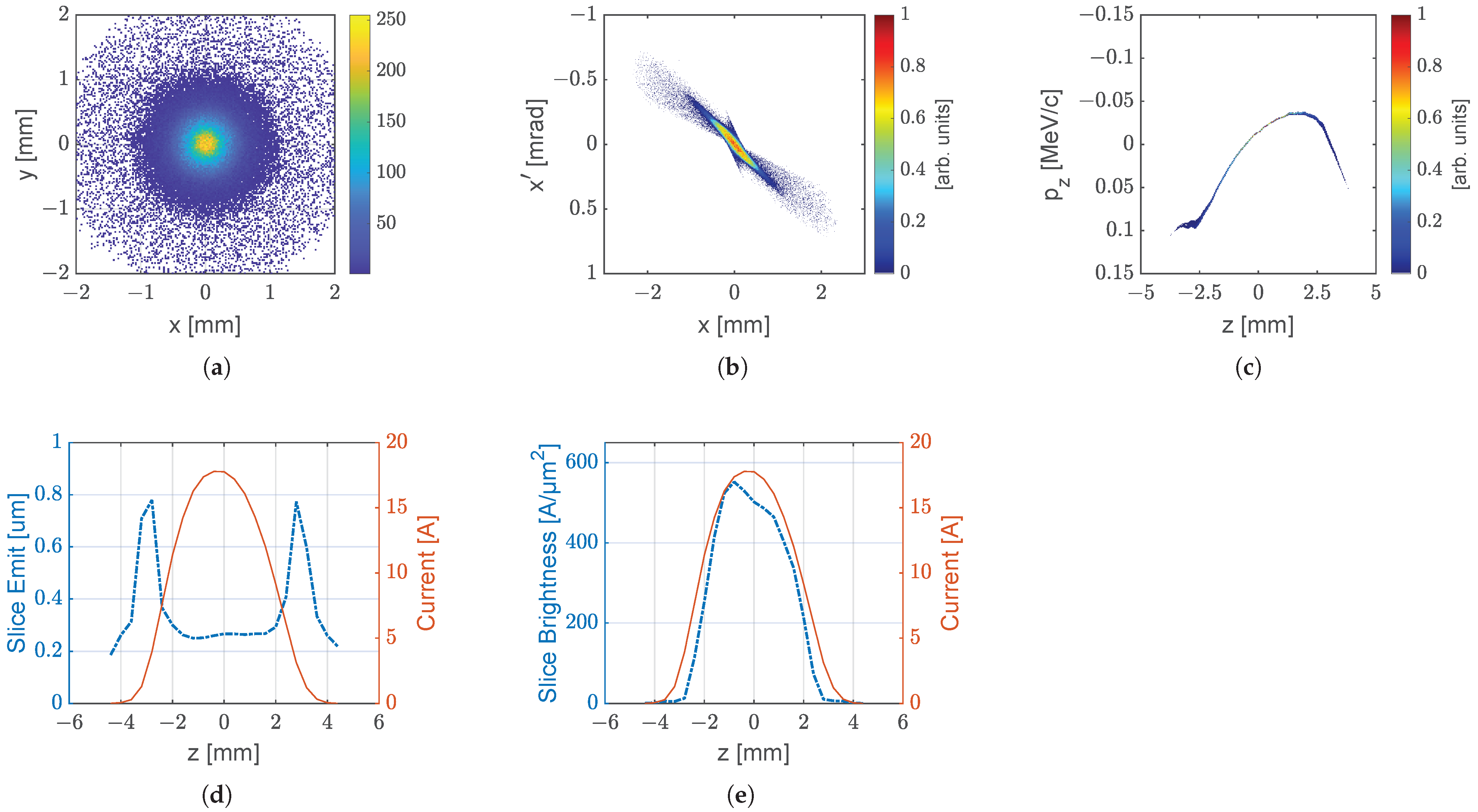
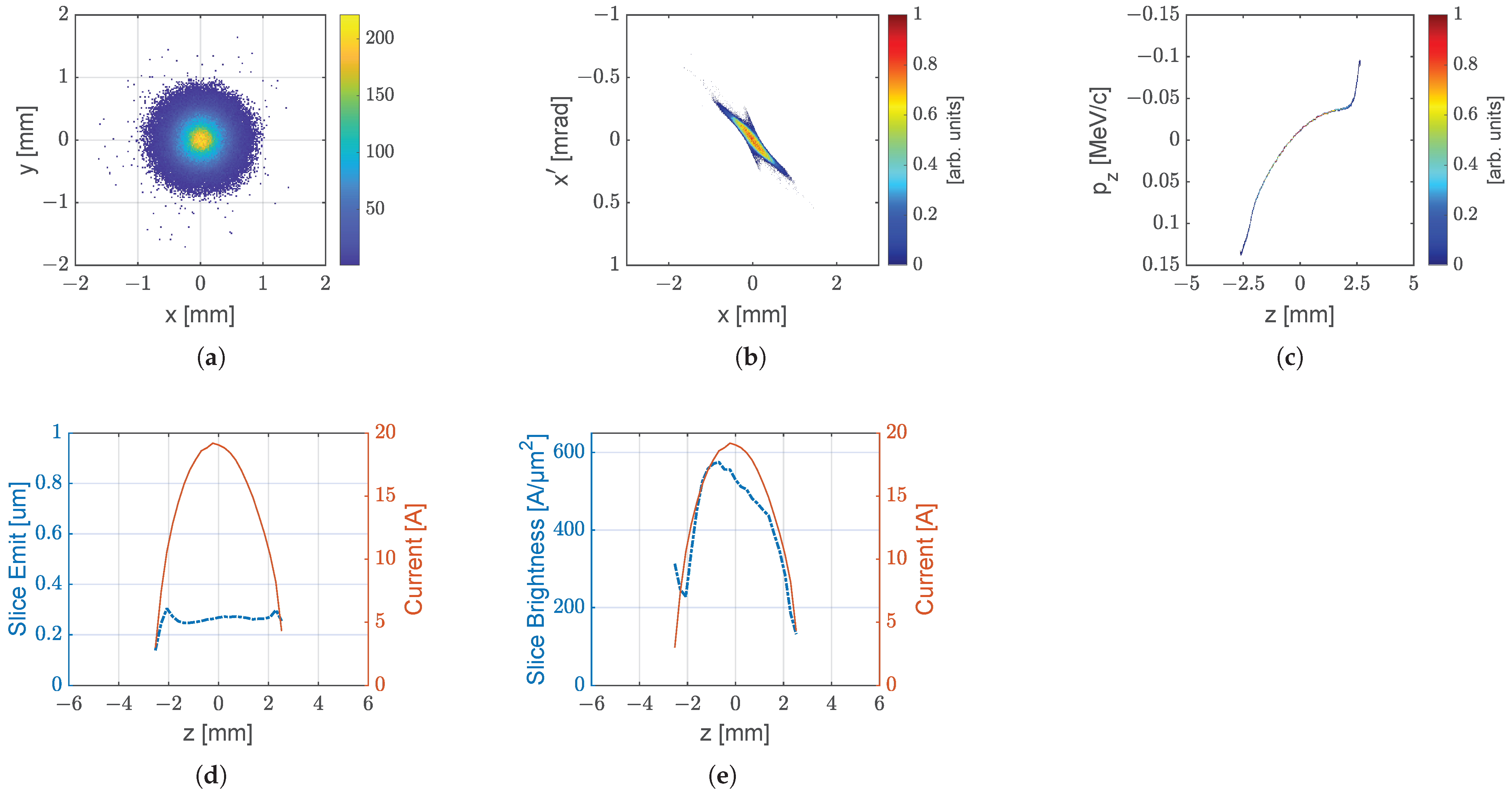
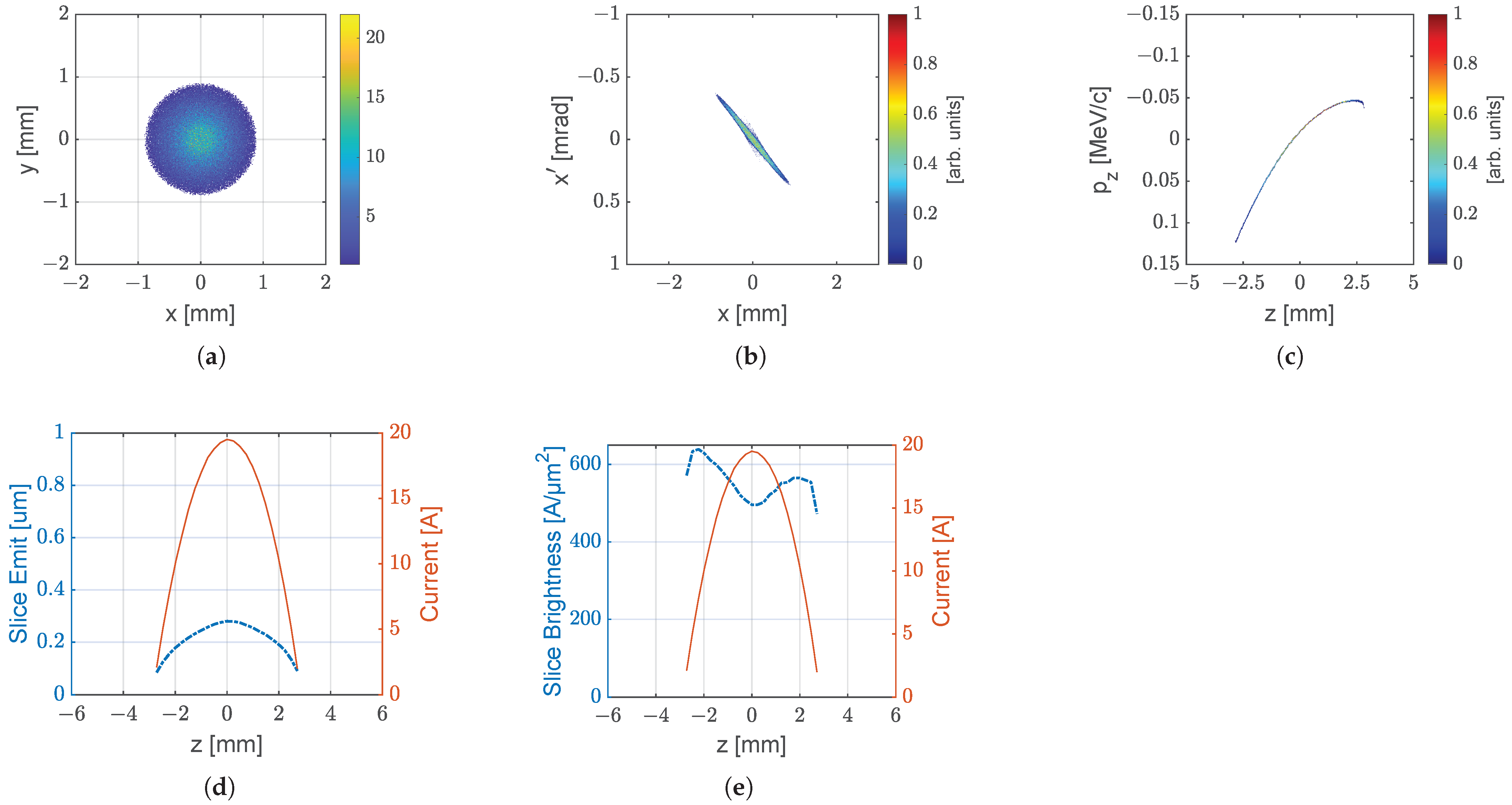
3.1. Beam Dynamics Simulations

To simulate the influence on the laser pulse shape, different longitudinal and transverse shapes were studied using ASTRA [40] for the geometrical settings of PITZ (Table 1). The parameters for the simulations matched the typical experimental conditions used over the last decade at PITZ [45]. The diameter of the BSA was varied from 0.8 to 1.6 mm, and the electric field at the cathode was 59.5 MV/m. This corresponds to a mean beam momentum of 6.5 MeV/c after the gun. The electron bunch was further accelerated in the booster to its final mean beam momentum of 18 MeV/c. The charge was set to 250 pC, and the laser pulse length was set to 11.7 ps (FWHM) for comparison across each shape. The main solenoid current I M a i n was varied between 360 A and 380 A to minimize the projected emittance ϵ n , x at a distance of 5.28 m downstream of the cathode (first EMSY after CDS booster in Figure 2). Further details on the simulation can be found in Appendix A.
The 5D brightness
B 5 D = s l = 0 23 2 · I s l ( t ) ϵ s l , x ( t ) · ϵ s l , y ( t )
of an electron bunch can be used as a first approximation for the achievable undulator performance of an X-ray FEL. Here, I s l ( t ) is the current of a slice taken from the electron bunch within its longitudinal RMS width σ z , and ϵ s l , x and ϵ s l , y are the slice emittances in the x- and y-planes of the respective slice. For the 5D brightness, the currents and emittances over 24 slices are summed over the whole electron bunch. The dimension of B 5 D in convenient units is [ A μ m 2 ] . In Table 1, the relative reduction in the projected emittance ϵ n , x and the B 5 D improvement with respect to a Gaussian longitudinal shape and with a radial uniform shape are presented.
As expected, the highest brightness was achieved for the ellipsoidal shape. However, achieving 3D ellipsoidal pulses in the UV range is a challenging task [14,16]. Flattop pulses are routinely achieved using the pulse-stacking technique [46,47]. Using a BSA to truncate the Gaussian beam profile of the photocathode laser significantly reduces the projected emittance when choosing a truncation of 0.9 σ [27]. A 15% reduction in the projected emittance was previously demonstrated at PITZ [29].
To find the optimum truncation level of a Gaussian temporal profile, several iterations were performed, with the lowest emittance achieved for a truncation of 1.5 σ . With proper temporal and spatial truncation of Gaussian pulses, a reduced projected emittance and improved brightness compared to flattop pulses can be expected, which underlines the potential application of our proposed slit-mask approach for high-brightness photoinjectors. The longitudinal phase space (LPS) of the electron bunch is critical for achieving high-brightness electron beams that drive X-ray FELs. Deleterious effects in LPS can hinder the FEL gain mechanism. Therefore, Table 1 also includes the longitudinal emittance ϵ z . This parameter underlines the importance of ellipsoidal pulse shapes. However, flattop, parabolic, and truncated Gaussian pulse shapes can achieve much higher FEL gains than Gaussian pulses.

3.2. Experiments at 514 nm

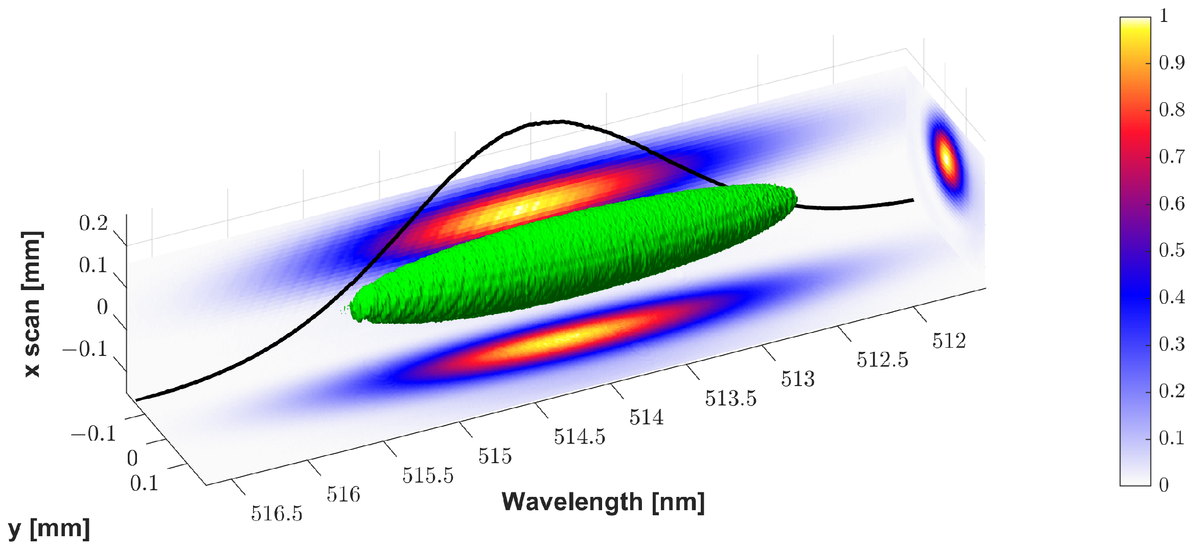
3.2.1. Characterization of Chirped Gaussian Pulses

To show the capabilities of the diagnostic scheme of 3D pulse reconstruction through slit-scan measurements using an imaging Czerny–Turner spectrograph, as well as the temporal and spectral characterizations of the laser pulse through SHG FROG measurements, Gaussian pulses were stretched to a duration of ∼15 ps. The 3D pulse reconstruction is presented in Figure 5. The projections in all directions were Gaussian distributions: x-y is the beam profile, and x- λ and y- λ are the 2D spectral distributions.
The performance of the pulse stretcher was investigated through SHG FROG measurements (Figure 6a), where the UV spectrograph served as the detector. The reconstructed temporal signal was a Gaussian pulse with a duration of 14.9 ps FWHM and a parabolic temporal phase (Figure 6b). The reconstructed spectral signal (1.15 nm FWHM) was also Gaussian with a parabolic spectral phase (Figure 6c).

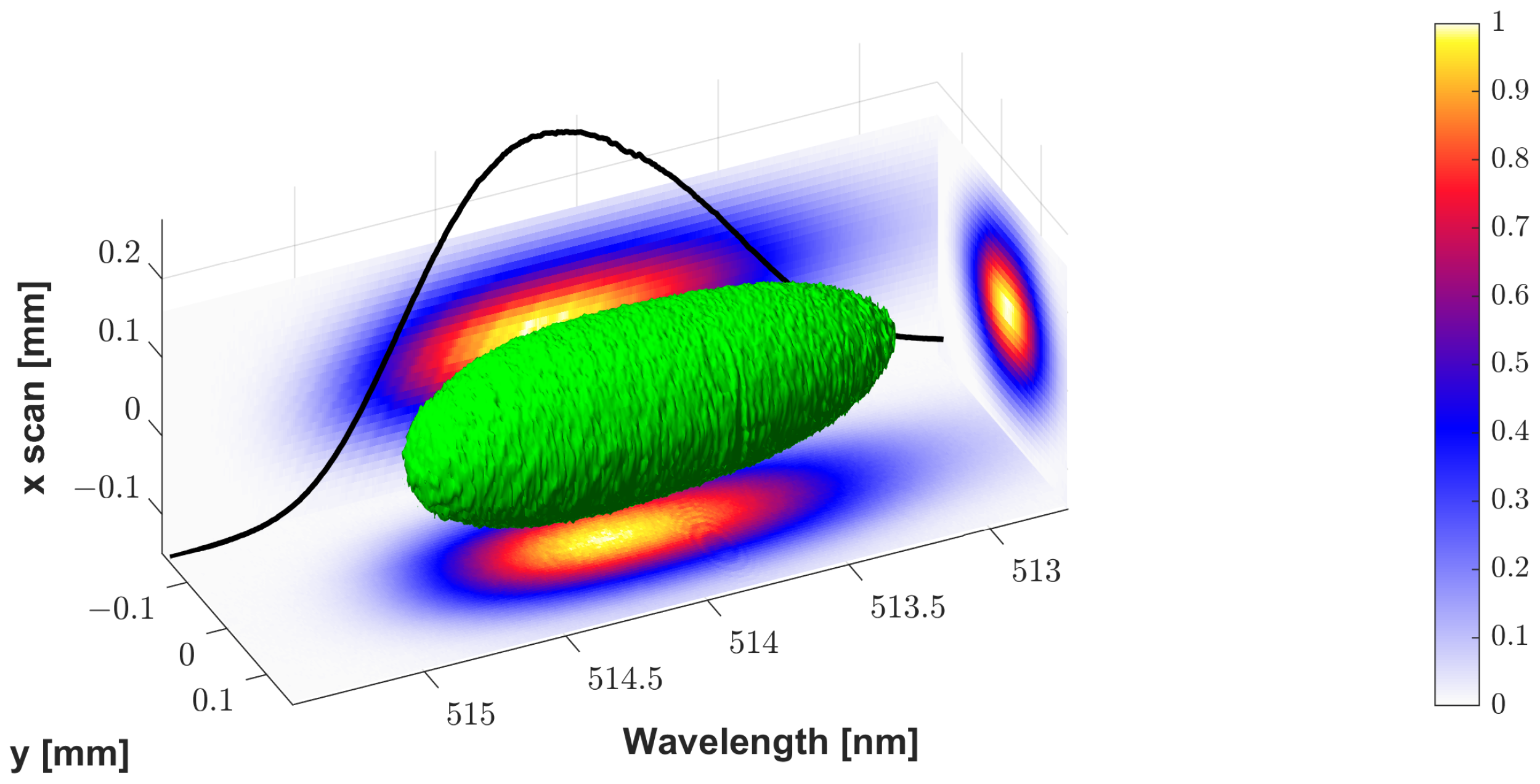
3.2.2. Characterization of Chirped Truncated Gaussian Pulses

When applying a slit mask in the symmetry plane of the grating stretcher, the spectral distribution can be cut. To align the slit mask in the stretcher, the slit-scan mirror of the spectrograph is driven to the maximum position of the Gaussian pulse, and then the position and width of the slit are adjusted to achieve the desired spectral shape. As shown in the SHG FROG measurements, the relationship between the time and spectral domains was nearly linear (Figure 6b). So, truncating the pulse in the spectral domain also shortened the pulse. Comparing Figure 5 without truncation and Figure 7 with truncation shows a significant reduction in the spectral width for the truncated Gaussian pulse. In addition, the wings of the spectral distribution are less pronounced than those for the Gaussian pulse. However, the achieved spectrum is not perfectly symmetric and shows a longer tail at shorter wavelengths.
The spectral and temporal characterizations of the truncated Gaussian pulse were performed using the SHG FROG measurements (Figure 8a), where the UV spectrograph was used as a detector. The reconstructed temporal signal was narrower than the Gaussian pulse with a duration of 13.3 ps FWHM and a parabolic temporal phase (Figure 8b). The reconstructed spectral signal (1.02 nm FWHM) deviated from a Gaussian distribution (Figure 8c).
Although pulse shaping was achieved using truncation of the spectrum, the temporal profile (Figure 8b) is best described using a super-Gaussian function
f ( t ) = A · e x p ( 0.5 · | ( t t 0 ) / σ | N ) ,
where the amplitude A = 0.99 , the RMS width σ = 5.84 ps, and the exponent of the super-Gaussian N = 2.55 . The reason the temporal profile is not a truncated Gaussian can be seen in the imperfectly symmetric cutting of the spectrum (Figure 7). The SHG FROG measurements are symmetric in time; therefore, the reconstruction is symmetric and shows small wings on both sides, which are best fitted using a super-Gaussian function. However, truncated Gaussian pulses using the approach of cutting in the symmetry plane of a pulse stretcher or compressor would be possible with a precisely tunable, motorized slit mask with a tunable position and controllable slit width to achieve a perfect truncation of 1.5 σ , similar to the flexibility of an LCOS SLM in a zero-dispersion stretcher for amplitude shaping.

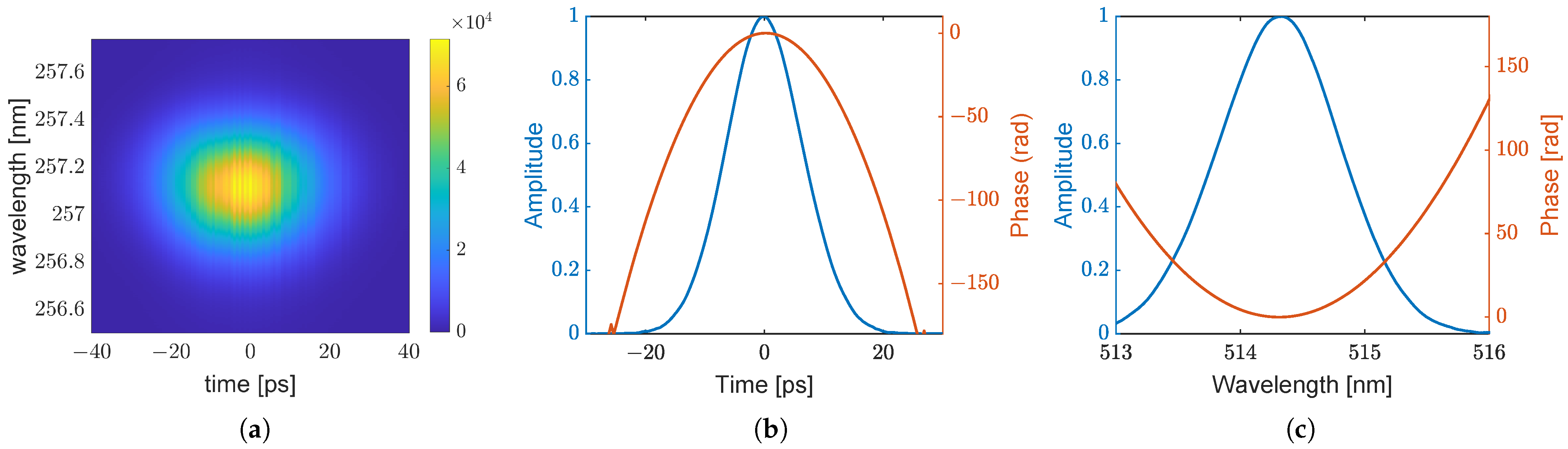
3.3. Experiments at 257 nm

Transferring the approach to stretcher or compressor setups at UV wavelengths is challenging due to the significantly smaller spectral bandwidth compared to 514 nm, which reduces the spatial width at the symmetry plane for applying a slit mask. The UV pulses from the PHAROS were stretched to 10 ps (FWHM), and a slit mask was applied to the symmetry plane of the stretcher. In Figure 9a, a stretched Gaussian pulse without an applied slit mask is shown. Compared to the pulse with an applied slit mask (Figure 9b), the differences are difficult to discern from the 3D representations. For better comparison, Figure 9c shows the spectra for both cases at a slit position of x = 0 mm.
Applying the slit mask to the UV stretcher reduced the RMS spectral width to 0.2116 nm, compared to 0.2231 nm without the mask. Compared to the experiments at 514 nm, no significant truncation was achieved, and the resulting shape after applying the UV slit mask was still Gaussian. In addition, due to the non-visibility of the 257 nm wavelength, careful alignment on the slit mask was more complicated in the used 8-times folded pulse stretcher, which is susceptible to spatial beam misalignment due to the insertion of the slit mask. Furthermore, minimizing the slit width to achieve sufficient truncation may degrade the UV beam profile.

4. Discussion

We conducted beam dynamics simulations to investigate brightness improvement at PITZ and found that longitudinally truncated Gaussian and super-Gaussian pulse shapes exhibit superior brightness compared to traditional Gaussian profiles. The simulations were performed for a 250 pC bunch charge, although the relative emittance reduction and brightness improvement can be scaled to the envisioned 3 nC bunch charge. Considering halo reduction and longitudinal phase space, transversely and longitudinally truncated chirped Gaussian laser pulses can be considered a simplified approach for photocathode lasers compared to 3D ellipsoids. While transverse shaping is typically achieved using a beam-shaping aperture imaged onto the photocathode, we studied an alternative approach by inserting a slit mask into the symmetry plane of a pulse stretcher at 514 nm for longitudinal pulse shaping. Our method yielded a super-Gaussian temporal distribution, as measured via SHG FROG. Better approximations of truncated Gaussian pulses can be achieved with optimized alignment and positioning of the slit mask. Notably, SHG FROG is limited to measuring symmetric signals; therefore, it inherently reports a super-Gaussian profile when the applied truncation lacks spectral symmetry.

4.1. Quality of Shaped UV Pulses and Efficiency

Due to the narrow spectral width at UV wavelengths, applying a slit mask in the UV stretcher did not achieve sufficient truncation. Only a slight reduction in spectral width was achieved. Further improvement of the slit mask for the UV stretcher is necessary. Optimization of the longitudinal truncation showed an optimum value at 1.5 σ . Combined with transverse truncation using the BSA at 0.9 σ , a pulse-shaping scheme with high efficiency becomes possible. In the case of the UV stretcher (∼60 % efficiency), this would lead to approximately 33% of the input pulse energy (2 µJ), or ∼660 nJ, being sent to the photocathode. However, achieving a truncation of 1.5 σ could lead to beam profile degradation, which may hinder performance. Alternatively, truncated Gaussian longitudinal profiles could be realized at 514 nm, and SHG to 257 nm could be further investigated.

4.2. Application in THz Undulators

Assuming a QE of 5% for a C s 2 Te photocathode, it seems possible to achieve more than 6 nC of bunch charge, providing some reserve for the envisioned 3 nC required for experiments with the THz SASE FEL. Although the THz SASE FEL has less stringent emittance requirements compared to X-Ray FELs [38], improved emittance and reduced halo will increase the total photon flux, allowing for better matching of the electron bunch into the undulator (Appendix A).

4.3. Simplification for Alkali Antimonide Photocathodes

Pulse shaping at a 514 nm wavelength is suitable for alkali antimonide photocathodes. The broader spectral bandwidth available at this green wavelength facilitates the use of slit masks in the symmetry plane of pulse stretchers, making it more feasible than at UV wavelengths. Additionally, the higher laser energy available at 514 nm reduces the need for efficiency gains through direct shaping within the stretcher. Instead, enhanced brightness can be achieved through three-dimensional amplitude shaping to achieve ellipsoid pulses [16] (Appendix A).

4.4. Transfer to Other Photocathode Lasers

The benefit of cutting the spectrum in the symmetry plane of a pulse stretcher or compressor lies in its ability to decouple pulse-duration tuning from other system parameters. Utilizing either 514 nm or 257 nm for direct application to different photocathode materials, as available on the PHAROS laser, enables independent control over the pulse duration without necessitating additional frequency-conversion steps. In contrast, Yb-based lasers employing chirped pulse amplification with a slit mask in the compressor permit the tuning of the pulse duration; however, this flexibility is compromised by a two-stage frequency conversion to UV, which requires the precise optimization of the conversion geometry to achieve sufficient efficiency. However, the scheme of applying a slit mask in the symmetry plane of a pulse compressor becomes even more feasible due to the larger spectral width around 1030 nm.

Author Contributions

Conceptualization, A.H. and M.K.; formal analysis, A.H., M.K. and S.Z.; investigation, A.H.; resources, A.H. and J.G.; writing—original draft preparation, A.H. and S.Z.; writing—review and editing, A.H., M.G., M.K., F.S. and S.Z.; visualization, A.H. and S.Z.; supervision, M.K.; project administration, M.G., M.K. and F.S.; funding acquisition, M.K. and F.S. All authors have read and agreed to the published version of the manuscript.

Funding

This work was supported by the European XFEL research and development program.

Data Availability Statement

The data that support the findings of this study are available upon reasonable request from the authors.

Conflicts of Interest

The authors declare no conflicts of interest.

Abbreviations

The following abbreviations are used in this manuscript:
ASTRAA Space Charge Tracking Algorithm
BSAbeam-shaping aperture
DESYDeutsches Elektronen-Synchrotron
EMSYemittance measurement system
FELfree-electron laser
FROGfrequency-resolved optical gating
PITZPhoto Injector Test Facility at DESY in Zeuthen
RFradio frequency
RMSroot mean square
UVultraviolet
Yb:KGWytterbium-doped potassium gadolinium tungstate

Appendix A

To support the proposed scheme of chirping the bandwidth-limited pulses of the PHAROS laser and applying a slit mask in the symmetry plane of the stretcher for amplitude shaping, simulations were carried out using LAB2 [48]. The results are shown in Figure A1.
Figure A1. LAB2 simulation of pulse stretching and application of an amplitude mask in the symmetry plane of the pulse stretcher, generating truncated chirped Gaussian pulses. (a) Intensity and relative instantaneous frequency of a bandwidth-limited pulse with a duration of 260 fs FWHM from the PHAROS laser system. (b) Stretching the pulse to ∼15 ps using a grating stretcher leads to a linear relationship between the temporal domain and instantaneous frequency. (c) Application of different levels of truncation to a Gaussian spectrum in the symmetry plane of the grating stretcher: no truncation (blue), small truncation (orange), medium truncation (yellow), and strong truncation (purple). (d) Temporal intensity profile of the pulses using the same color coding scheme. (e) SHG intensity autocorrelation of the pulses using the same color coding scheme.
Photonics 12 00460 g0a1
Bandwidth-limited pulses with a duration of 260 fs FWHM at a 514 nm wavelength are depicted in Figure A1a. These pulses are then stretched to ∼15 ps using the grating stretcher described in Section 2.2. Due to the stretching, a linear relationship between the temporal domain and instantaneous frequency is introduced (Figure A1b). This forms the basis for the amplitude shaping of the chirped pulses in zero-dispersion stretchers with LCOS SLMs [13,15,16]. Here, a simplified approach, which applies a slit mask directly in the symmetry plane of the pulse stretcher for truncation in the spectral domain, is studied (Figure A1c). The resulting pulse shapes in the time domain are shown in Figure A1d. It can be seen that the simplified approach of inserting a slit mask is limited by either not achieving significant truncation in the time domain for small spectral truncation or significant additional modulation in the time domain for strong truncation in the spectral domain. However, only a sharp binary mask is considered for the simulation, and neither soft edges for the mask nor slight misalignment are included. SHG intensity autocorrelation traces for the respective truncated chirped Gaussian pulse are shown in Figure A1e.
Further details of the simulations in Table 1 are provided here. For each BSA size between 0.8 mm and 1.6 mm, the projected emittance was optimized by scanning the main solenoid current between 360 A and 380 A. Other parameters, such as the beam momentum, charge, and laser pulse duration for each shape, were kept constant. The beam profile at the photocathode, transverse phase space, longitudinal phase space, and slice emittance are shown for the optimized cases for a Gaussian longitudinal profile with a radial uniform transverse profile (Figure A2), a super-Gaussian longitudinal profile with a truncated Gaussian transverse profile (Figure A3), a truncated Gaussian longitudinal profile with a truncated Gaussian transverse profile (Figure A4), and an ellipsoidal longitudinal profile with a truncated Gaussian transverse profile (Figure A5).
Figure A2. ASTRA simulation for the best case of a Gaussian longitudinal profile with a radial uniform transverse profile. (a) Transverse beam profile at the photocathode for a BSA size of 1.1 mm. (b) Transverse phase space 5.28 m downstream of the photocathode. (c) Longitudinal phase space. (d) Slice emittance and current. (e) Slice brightness and current.
Photonics 12 00460 g0a2
The baseline for studying projected emittance reduction and brightness improvement was a Gaussian longitudinal profile with a radial uniform transverse profile. The transverse beam profile at the photocathode is depicted in Figure A2a and shows a beam halo, which also transfers to the transverse phase space (Figure A2b). The longitudinal distribution is shown for the LPS (Figure A2c), the slice emittance and the current (Figure A2d), and the slice brightness (Figure A2e).
Similar behavior can be observed for the super-Gaussian longitudinal profile. But due to the transverse truncated Gaussian profile, a reduced halo can be observed in the transverse phase space (Figure A3b).
Figure A3. ASTRA simulation of the best case of a super-Gaussian longitudinal profile with a truncated Gaussian transverse profile. (a) Transverse beam profile at the photocathode for a BSA size of 1.3 mm. (b) Transverse phase space 5.28 m downstream of the photocathode. (c) Longitudinal phase space. (d) Slice emittance and current. (e) Slice brightness and current.
Photonics 12 00460 g0a3
A significantly better halo reduction for the beam profile at the cathode (Figure A4a) and in the transverse phase space (Figure A4b) can be observed for the truncated Gaussian longitudinal and transverse profile. The slice emittance is also further reduced compared to the previously shown electron bunch shapes (Figure A4d).
The best case for generating high-brightness electron bunches to drive X-Ray FELs is the ellipsoidal longitudinal profile with a truncated Gaussian transverse profile. The halo is minimized for the beam profile at the cathode (Figure A5a) and the transverse phase (Figure A5b), which allows improved matching of the beam to the undulator and minimizes unwanted parasitic electrons that could damage the undulator. The longitudinal phase space is only slightly bent (Figure A5c) and can be linearized with a higher harmonic cavity, which is implemented in the accelerator scheme at X-ray FELs and plays a crucial role in bunch compression. For the other pulse shapes presented here, only a fraction of the phase space can be linearized, limiting the FEL gain.
Figure A4. ASTRA simulation of the best case of a truncated Gaussian longitudinal profile with a truncated Gaussian transverse profile. (a) Transverse beam profile at the photocathode for a BSA size of 1.1 mm. (b) Transverse phase space 5.28 m downstream of the photocathode. (c) Longitudinal phase space. (d) Slice emittance and current. (e) Slice brightness and current.
Photonics 12 00460 g0a4
Figure A5. ASTRA simulation of the best case of an ellipsoidal longitudinal profile with a truncated Gaussian transverse profile. (a) Transverse beam profile at the photocathode for a BSA size of 1.1 mm. (b) Transverse phase space 5.28 m downstream of the photocathode. (c) Longitudinal phase space. (d) Slice emittance and current. (e) Slice brightness and current.
Photonics 12 00460 g0a5

References

  1. Serafini, L.; Rosenzweig, J.B. Envelope analysis of intense relativistic quasilaminar beams in rf photoinjectors: A theory of emittance compensation. Phys. Rev. E 1997, 55, 7565–7590. [Google Scholar] [CrossRef]
  2. Limborg-Deprey, C.; Tomizawa, H. Maximizing brightness in photoinjectors. Int. J. Mod. Phys. 2007, 22, 3864–3881. [Google Scholar] [CrossRef]
  3. Sannibale, F. High-brightness electron injectors for high-duty cycle X-ray free electron lasers. Front. Phys. 2023, 11, 1187346. [Google Scholar] [CrossRef]
  4. Kapchinskij, I.M.; Vladimirskij, V.V. Limitations Of Proton Beam Current In A Strong Focusing Linear Accelerator Associated with The Beam Space Charge. In Proceedings of the 2nd International Conference on High-Energy Accelerators, Geneva, Switzerland, 14–19 September 1959; pp. 274–287. [Google Scholar]
  5. Kellogg, O. Foundations of Potential Theory; Reprint from the 1st ed. of 1929; Dover: New York, NY, USA, 1954. [Google Scholar]
  6. Reiser, M. Theory and Design of Charged Particle Beams; Wiley-VCH: Weinheim, Germany, 2008. [Google Scholar]
  7. Ha, G.; Kim, K.J.; Power, J.G.; Sun, Y.; Piot, P. Bunch shaping in electron linear accelerators. Rev. Mod. Phys. 2022, 94, 25006. [Google Scholar] [CrossRef]
  8. Serafini, L. Improving the beam quality of RF guns by correction of RF and space-charge effects. AIP Conf. Proc. 1992, 279, 645–674. [Google Scholar] [CrossRef]
  9. Luiten, O.J.; van der Geer, S.B.; de Loos, M.J.; Kiewiet, F.B.; van der Wiel, M.J. How to Realize Uniform Three-Dimensional Ellipsoidal Electron Bunches. Phys. Rev. Lett. 2004, 93, 094802. [Google Scholar] [CrossRef]
  10. Will, I.; Templin, H.I.; Schreiber, S.; Sandner, W. Photoinjector drive laser of the FLASH FEL. Opt. Express 2011, 19, 23770–23781. [Google Scholar] [CrossRef]
  11. Winkelmann, L.; Choudhuri, A.; Grosse-Wortmann, U.; Hartl, I.; Li, C.; Mohr, C.; Müller, J.; Peters, F.; Pfeiffer, S.; Salman, S. The European XFEL Photocathode Laser. In Proceedings of the 39th in Free Electron Laser Conference, Proc. FEL’19, Hamburg, Germany, 26–30 August 2019; JACoW Publishing: Geneva, Switzerland, 2019; pp. 423–426. [Google Scholar] [CrossRef]
  12. Li, C.; Akcaalan, O.; Frede, M.; Grosse-Wortmann, U.; Hartl, I.; Mohr, C.; Puncken, O.; Seidel, M.; Tuennermann, H.; Vidoli, C.; et al. Photocathode Laser Development for Superconducting X-ray Free Electron Lasers at DESY. In Proceedings of the 12th in International Particle Accelerator Conference, Proc. IPAC’21, Virtual, 24–28 May 2021; JACoW Publishing: Geneva, Switzerland, 2021; pp. 3599–3601. [Google Scholar] [CrossRef]
  13. Mironov, S.Y.; Potemkin, A.K.; Gacheva, E.I.; Andrianov, A.V.; Zelenogorskii, V.V.; Krasilnikov, M.; Stephan, F.; Khazanov, E.A. Shaping of cylindrical and 3D ellipsoidal beams for electron photoinjector laser drivers. Appl. Opt. 2016, 55, 1630–1635. [Google Scholar] [CrossRef]
  14. Koschitzki, C.; Qian, H.; Aboulbanine, Z.; Adhikari, G.; Aftab, N.; Boonpornprasert, P.; Georgiev, G.; Good, J.; Gross, M.; Hoffmann, A.; et al. Chirped Pulse Laser Shaping for High Brightness Photoinjectors. In Proceedings of the 40th International Free Electron Laser Conference, Proc. FEL2022, Trieste, Italy, 22–26 August 2022; JACoW Publishing: Geneva, Switzerland, 2022; pp. 345–348. [Google Scholar] [CrossRef]
  15. Hoffmann, A.; Good, J.; Gross, M.; Krasilnikov, M.; Stephan, F. Towards Implementation of 3D Amplitude Shaping at 515 nm and First Pulseshaping Experiments at PITZ. Photonics 2024, 11, 6. [Google Scholar] [CrossRef]
  16. Hoffmann, A.; Good, J.; Gross, M.; Krasilnikov, M.; Stephan, F. Generation of UV Ellipsoidal Pulses by 3D Amplitude Shaping for Application in High-Brightness Photoinjectors. Photonics 2024, 11, 779. [Google Scholar] [CrossRef]
  17. Galdi, A.; Balajka, J.; DeBenedetti, W.J.I.; Cultrera, L.; Bazarov, I.V.; Hines, M.; Maxson, J.M. Reduction of surface roughness emittance of Cs3Sb photocathodes grown via codeposition on single crystal substrates. Appl. Phys. Lett. 2021, 118, 244101. [Google Scholar] [CrossRef]
  18. Mohanty, S.K.; Krasilnikov, M.; Oppelt, A.; Stephan, F.; Sertore, D.; Monaco, L.; Pagani, C.; Hillert, W. Development and Characterization of Multi-Alkali Antimonide Photocathodes for High-Brightness RF Photoinjectors. Micromachines 2023, 14, 1182. [Google Scholar] [CrossRef] [PubMed]
  19. Brinkmann, R.; Schneidmiller, E.; Sekutowicz, J.; Yurkov, M. Prospects for CW and LP operation of the European XFEL in hard X-ray regime. Nucl. Instrum. Methods Phys. Res. Sect. A Accel. Spectrom. Detect. Assoc. Equip. 2014, 768, 20–25. [Google Scholar] [CrossRef]
  20. Sekutowicz, J.; Ayvazyan, V.; Barlak, M.; Branlard, J.; Cichalewski, W.; Grabowski, W.; Kostin, D.; Lorkiewicz, J.; Merz, W.; Nietubyc, R.; et al. Research and development towards duty factor upgrade of the European X-ray Free Electron Laser linac. Phys. Rev. ST Accel. Beams 2015, 18, 50701. [Google Scholar] [CrossRef]
  21. Chatterley, A.; Karamatskos, E.; Schouder, C.; Christiansen, L.; Jørgensen, A.; Mullins, T.; Küpper, J.; Stapelfeldt, H. Communication: Switched wave packets with spectrally truncated chirped pulses. J. Chem. Phys. 2018, 148, 221105. [Google Scholar] [CrossRef]
  22. Kafka, K.; Papernov, S.; Demos, S. Enhanced laser conditioning using temporally shaped pulses. Opt. Lett. 2018, 43, 1239–1242. [Google Scholar] [CrossRef]
  23. Altucci, C.; Bruzzese, R.; Lisio, C.; Nisoli, M.; Priori, E.; Stagira, S.; Pascolini, M.; Poletto, L.; Villoresi, P.; Tosa, V.; et al. Phase-matching analysis of high-order harmonics generated by truncated Bessel beams in the sub-10-fs regime. Phys. Rev. A 2003, 68, 033806. [Google Scholar] [CrossRef]
  24. Jin, C.; Lin, C. Comparison of high-order harmonic generation of Ar using truncated Bessel and Gaussian beams. Phys. Rev. A 2012, 85, 033423. [Google Scholar] [CrossRef]
  25. Worku, N.; Gross, H. Spatially truncated Gaussian pulsed beam and its application in modeling diffraction of ultrashort pulses from hard apertures. J. Opt. Soc. Am. A 2020, 37, 317–326. [Google Scholar] [CrossRef]
  26. Pan, L.; Lü, B. Spectral behavior of diffracted chirped Gaussian pulses in the far field. Optik 2004, 115, 57–66. [Google Scholar] [CrossRef]
  27. Rao, T.; Dowell, D. (Eds.) An Engineering Guide To Photoinjectors; CreateSpace Independent Publishing: Charleston, SC, USA, 2013; Available online: https://arxiv.org/abs/1403.7539 (accessed on 10 February 2025).
  28. Zhou, F.; Brachmann, A.; Emma, P.; Gilevich, S.; Huang, Z. Impact of the spatial laser distribution on photocathode gun operation. Phys. Rev. ST Accel. Beams 2012, 15, 090701. [Google Scholar] [CrossRef]
  29. Groß, M.; Aftab, N.; Boonpornprasert, P.; Chen, Y.; Georgiev, G.; Good, J.; Koschitzki, C.; Krasilnikov, M.; Li, X.; Lishilin, O.; et al. Characterization of Low Emittance Electron Beams Generated by Transverse Laser Beam Shaping. In Proceedings of the 12th International Particle Accelerator Conference, Proc. IPAC ’21, Campinas, Brazil, 24–28 May 2021; JACoW Publishing: Geneva, Switzerland, 2021; pp. 2690–2692. [Google Scholar] [CrossRef]
  30. Zhu, X.; Broemmelsiek, D.; Shin, Y. Theoretical and numerical analyses of a slit-masked chicane for modulated bunch generation. J. Instrum. 2015, 10, P10042. [Google Scholar] [CrossRef]
  31. Muggli, P.; Yakimenko, V.; Babzien, M.; Kallos, E.; Kusche, K. Generation of Trains of Electron Microbunches with Adjustable Subpicosecond Spacing. Phys. Rev. Lett. 2008, 101, 054801. [Google Scholar] [CrossRef] [PubMed]
  32. Andruszkow, J.; Aune, B.; Ayvazyan, V.; Baboi, N.; Bakker, R.; Balakin, V.; Barni, D.; Bazhan, A.; Bernard, M.; Bosotti, A.; et al. First Observation of Self-Amplified Spontaneous Emission in a Free-Electron Laser at 109 nm Wavelength. Phys. Rev. Lett. 2000, 85, 3825–3829. [Google Scholar] [CrossRef]
  33. Ackermann, W.; Asova, G.; Ayvazyan, V.; Azima, A.; Baboi, N.; Baehr, J.; Balandin, V.; Beutner, B.; Brandt, A.; Bolzmann, A.; et al. Operation of a free-electron laser from the extreme ultraviolet to the water window. Nat. Photonics 2007, 1, 336–342. [Google Scholar] [CrossRef]
  34. Altarelli, M.; Brinkmann, R.; Chergui, M.; Decking, W.; Dobson, B.; Düsterer, S.; Grübel, G.; Graeff, W.; Graafsma, H.; Hajdu, J.; et al. XFEL: The European X-ray Free-Electron Laser; Technical Design Report; DESY: Hamburg, Germany, 2006. [Google Scholar] [CrossRef]
  35. Decking, W.; Abeghyan, S.; Abramian, P.; Abramsky, A.; Aguirre, A.; Albrecht, C.; Alou, P.; Altarelli, M.; Altmann, P.; Amyan, K.; et al. A MHz-repetition-rate hard X-ray free-electron laser driven by a superconducting linear accelerator. Nat. Photonics 2020, 14, 391–397. [Google Scholar] [CrossRef]
  36. Loisch, G.; Chen, Y.; Koschitzki, C.; Qian, H.; Gross, M.; Hannah, A.; Hoffmann, A.; Kalantaryan, D.; Krasilnikov, M.; Lederer, S.; et al. Direct measurement of photocathode time response in a high-brightness photoinjector. Appl. Phys. Lett. 2022, 120, 104102. [Google Scholar] [CrossRef]
  37. Krasilnikov, M.; Aboulbanine, Z.; Adhikari, G.; Aftab, N.; Boonpornprasert, P.; Bousonville, M.; Brinker, F.; Castro Carballo, M.E.; Georgiev, G.; Good, J.; et al. RF Performance of a Next-Generation L-Band RF Gun at PITZ. In Proceedings of the 31st International Linear Accelerator Conference, LINAC2022, Liverpool, UK, 28 August–2 September 2022; JACoW Publishing: Geneva, Switzerland, 2022; pp. 699–702. [Google Scholar] [CrossRef]
  38. Krasilnikov, M.; Aboulbanine, Z.; Adhikari, G.; Aftab, N.; Asoyan, A.; Boonpornprasert, P.; Davtyan, H.; Georgiev, G.; Good, J.; Grebinyk, A.; et al. First high peak and average power single-pass THz free-electron laser in operation. Phys. Rev. Accel. Beams 2025, 28, 030701. [Google Scholar] [CrossRef]
  39. Li, X.; Amirkhanyan, Z.; Grebinyk, A.; Gross, M.; Komar, Y.; Riemer, F.; Asoyan, A.; Boonpornprasert, P.; Borchert, P.; Davtyan, H.; et al. Demonstration of ultra-high dose rate electron irradiation at FLASHlab@PITZ. Phys. Med. Biol. 2025. [Google Scholar] [CrossRef]
  40. Flöttmann, K. ASTRA—A Space Charge Tracking Algorithm. Available online: https://www.desy.de/~mpyflo/ (accessed on 13 March 2025).
  41. van der Geer, S.B.; de Loos, M.J. General Particle Tracer (GPT). Available online: https://www.pulsar.nl/gpt/ (accessed on 17 March 2025).
  42. Qiang, J.; Lidia, S.; Ryne, R.; Limborg-Deprey, C. Three-dimensional quasistatic model for high brightness beam dynamics simulation. Phys. Rev. ST Accel. Beams 2006, 9, 044204. [Google Scholar] [CrossRef]
  43. Trebino, R.; De Long, K.W.; Fittinghoff, D.N.; Sweetser, J.N.; Krumbügel, M.A.; Richman, B.A.; Kane, D.J. Measuring ultrashort laser pulses in the time-frequency domain using frequency-resolved optical gating. Rev. Sci. Instrum. 1997, 68, 3277–3295. [Google Scholar] [CrossRef]
  44. Sweetser, J.N.; Fittinghoff, D.N.; Trebino, R. Transient-grating frequency-resolved optical gating. Opt. Lett. 1997, 22, 519–521. [Google Scholar] [CrossRef] [PubMed]
  45. Krasilnikov, M.; Stephan, F.; Asova, G.; Grabosch, H.J.; Groß, M.; Hakobyan, L.; Isaev, I.; Ivanisenko, Y.; Jachmann, L.; Khojoyan, M.; et al. Experimentally minimized beam emittance from an L-band photoinjector. Phys. Rev. ST Accel. Beams 2012, 15, 100701. [Google Scholar] [CrossRef]
  46. Will, I. Generation of flat-top picosecond pulses by means of a two-stage birefringent filter. Nucl. Instrum. Methods Phys. Res. Sect. A Accel. Spectrom. Detect. Assoc. Equip. 2008, 594, 119–125. [Google Scholar] [CrossRef]
  47. Liu, F.; Huang, S.; Si, S.; Zhao, G.; Liu, K.; Zhang, S. Generation of picosecond pulses with variable temporal profiles and linear polarization by coherent pulse stacking in a birefringent crystal shaper. Opt. Express 2019, 27, 1467–1478. [Google Scholar] [CrossRef]
  48. Schmidt, B.; Hacker, M.; Stobrawa, G.; Feurer, T. LAB2—A Virtual Femtosecond Laser Lab. Available online: http://www.lab2.de (accessed on 13 July 2012).
Figure 1. A Gaussian spectrum (blue line) can be truncated with a hard cut at 1 σ (red line) to avoid the wings of the Gaussian distribution. Within 1 σ , the remaining spectral shape can be a close approximation of other advantageous shapes for high-brightness beams, e.g., an ellipsoidal shape with the same width (yellow line).
Photonics 12 00460 g001
Figure 2. Layout of the PITZ accelerator and beam diagnostics. Starting from the C s 2 Te photocathode in the gun, photoelectrons are accelerated in the RF gun and the booster up to 23 MeV/c. Dispersive arms (LEDA, HEDA1) allow for the momentum characterization of the electron bunches. The longitudinal electron beam distribution is measured by a TDS on a screen in the phase-space tomography (PST) section. Different positions allow for the characterization of projected emittances by scanning horizontal and vertical slits across the electron beam (EMSY). The combination of EMSY and TDS enables the measurement of the slice emittance.
Photonics 12 00460 g002
Figure 3. Experimental setup for generating truncated chirped Gaussian laser pulses. (a) Bandwidth-limited pulses of 260 fs from the 514 nm or 257 nm output of the PHAROS laser are chirped by individual grating stretchers for each wavelength. (b) Fundamental scheme of applying an amplitude mask in the symmetry plane of a pulse stretcher.
Photonics 12 00460 g003
Figure 4. Working principle of the 3D reconstruction of a chirped pulse using a Czerny–Turner 2D imaging spectrograph. A movable mirror scans the laser beam across the entrance slit of the spectrograph, allowing for the reconstruction of the chirped pulse. To achieve proper imaging conditions in the spectrograph, an alignment CCD is placed in the plane of the entrance slit.
Photonics 12 00460 g004
Figure 5. Three-dimensional visualization of a chirped Gaussian pulse from a slit-scan measurement.
Photonics 12 00460 g005
Figure 6. SHG FROG characterization of a stretched Gaussian pulse. (a) Measured signal of the UV spectrograph. (b) Reconstruction of the amplitude and phase in the time domain. (c) Reconstruction of the amplitude and phase in the spectral domain.
Photonics 12 00460 g006
Figure 7. Three-dimensional visualization of a chirped truncated Gaussian pulse from a slit-scan measurement.
Photonics 12 00460 g007
Figure 8. SHG FROG characterization of a stretched truncated Gaussian pulse. (a) Measured signal of the UV spectrograph. (b) Reconstruction of the amplitude and phase in the time domain. (c) Reconstruction of the amplitude and phase in the spectral domain.
Photonics 12 00460 g008
Figure 9. Application of a slit mask to the symmetry plane of the UV stretcher. (a) Three-dimensional representation of a chirped Gaussian pulse without an applied slit mask. (b) Three-dimensional representation of a chirped Gaussian pulse with an applied slit mask. (c) Comparison of the spectra of the slit scan for x = 0 mm.
Photonics 12 00460 g009
Table 1. Beam dynamics simulation at PITZ for different pulse shapes. Emittance reduction and brightness improvement are calculated with respect to a Gaussian longitudinal shape with a radial uniform shape.
Longitudinal ShapeTransversal ShapeBSA [mm] I Main [A] ϵ n , x [mm · mrad] σ z [ps] ϵ z [keV · mm] B 5 D [ A μ m 2 ] Relative ϵ n , x  Reduction B 5 D  Improvement
GaussianRadial uniform1.13730.5355.0932.33447100%1
Super-GaussianTruncated Gaussian (0.9 σ )1.33740.4394.7825.64995−18%1.4
FlattopTruncated Gaussian (0.9 σ )1.33740.3394.1717.57162−37%2.1
ParabolicTruncated Gaussian (0.9 σ )1.33740.3184.2616.98909−41%2.6
Truncated Gaussian (1.5 σ )Truncated Gaussian (0.9 σ )1.13740.2974.2517.49647−45%2.8
EllipsoidalTruncated Gaussian (0.9 σ )1.13760.2424.2913.712,775−55%3.7
Disclaimer/Publisher’s Note: The statements, opinions and data contained in all publications are solely those of the individual author(s) and contributor(s) and not of MDPI and/or the editor(s). MDPI and/or the editor(s) disclaim responsibility for any injury to people or property resulting from any ideas, methods, instructions or products referred to in the content.

