1. Introduction
With the rapid advancement of science and technology, the demand for visual information has surged across diverse fields, including scientific research, military defense, and industrial production. This increasing demand has intensified the need for ultra-wide-field imaging systems in contemporary optical imaging technologies. In astronomical observation, ultra-wide-field imaging systems can capture vast amounts of celestial information in a single frame, thereby aiding astronomers in unraveling the mysteries of the universe. In the military reconnaissance sector, these systems enable comprehensive battlefield monitoring and early warning capabilities. In machine vision, ultra-wide-field imaging systems significantly enhance the perception range and information processing abilities of industrial inspection and intelligent transportation systems. Notably, ultra-wide-field long-wave infrared optical systems (8.7~11.5 μm) used in military applications, with their exceptional detection capabilities and expansive imaging FoV, can effectively monitor and detect large areas under low-light or no-light conditions. These systems are thus crucial components in military optoelectronic instruments.
Traditional wide-field imaging optical systems typically employ solutions such as wide-field lenses, multi-lens combinations, or large-sized detectors to achieve broad fields of view. However, these approaches often result in increased system complexity and place stringent demands on detector performance. For example, Yang Shuwei designed a fisheye optical system with a 180° field of view (FoV), which effectively reduced image distortion and improved imaging quality by using four aspheric lenses, although the system is challenging to assemble and manufacture [
1]. Ryu Seonho developed a fisheye lens with a 180° FoV and a numerical aperture of 0.75 by integrating two optical systems to achieve FoV switching, which expanded the imaging range, but the system is relatively complex [
2]. Li Xijie designed an imaging spectrometer based on a fisheye lens, achieving an ultra-wide FoV of 180° and a working wavelength range of 0.629 μm~0.93 μm, expanding its application scenarios, but the system is relatively bulky, making integration and portable use challenging [
3]. In the field of panoramic annular optical structures, Gao Shaohua designed a large-diameter panoramic annular lens with a vertical FoV of 0°~100° for the visible light spectrum by tilting the arrangement of two optical channels, effectively enhancing the annular imaging capability [
4]. Yang Yingzhe proposed using Gaussian radial basis function freeform surfaces to achieve a vertical panoramic FoV of 30°~125°, a structure that is innovative but difficult to manufacture [
5]. Dewen Cheng designed a dual-field panoramic imager with a vertical FoV of 270° using a panoramic annular lens and a stitching method, but the complex surface posed significant machining challenges [
6]. Nichols developed a catadioptric periscope system with a FoV of (60°~100°) × 360° [
7] using two reflective mirrors to achieve all-round surveillance, but the system’s optical path design is complex and requires precise alignment. Yang Shen designed a six-channel stitched long-wave infrared optical system with a vertical FoV of 110° based on mirror principles, incorporating mirrors to achieve a wide FoV with a simple structure, although blind spots remained [
8].
Overall, current ultra-wide FoV imaging systems have made significant progress in structural innovation, imaging range, and application expansion, but there are still many shortcomings. Although fisheye and panoramic annular lenses can achieve ultra-large fields of view, their manufacturing and assembly processes are complex and costly due to the use of multiple aspheric designs or freeform surfaces [
9]. Reflective optical systems also suffer from the problem of missing central FoV [
10]. Furthermore, current ultra-wide-field long-wave infrared optical systems still exhibit structural flaws, such as low energy utilization efficiency, limited resolution, information loss, susceptibility to temperature variations, and imaging blind spots. These issues collectively restrict the practical application of such optical systems. Therefore, how to achieve a compact structure, easy fabrication, no blind spots, and efficient energy utilization in ultra-wide FoV imaging optical systems, while ensuring imaging quality and system stability, remains a core scientific and engineering challenge that urgently needs to be addressed.
To address these challenges, we propose a novel design solution that combines FoV stitching with a hybrid refractive–reflective optical structure, aiming to enhance the performance of ultra-wide-field long-wave infrared optical systems. Unlike fisheye systems that rely on multiple aspheric lenses, this design adopts a hybrid refractive–reflective dual-channel optical structure: one channel expands the FoV via a reflective optical path while the other uses refractive optical elements made entirely of germanium (Ge) to compensate for the viewing angle and effectively correct aberrations. The imaging fields of the two channels are precisely stitched together to achieve an ultra-wide-FoV infrared imaging system. Compared to approaches that rely solely on complex aspheric lens designs or multi-channel stitching, this design offers notable innovations: First, the hybrid structure reduces dependence on high-precision aspheric lenses, easing manufacturing and alignment challenges. Second, the dual-channel configuration enhances system flexibility and real-time responsiveness while better balancing image quality with compactness. Third, the use of all-Ge optics improves transmittance and imaging performance in the infrared band, enhancing environmental adaptability. Additionally, the system includes a thorough analysis of alignment errors and the impact of temperature variations on imaging quality, further ensuring stability and reliability.
In summary, compared to existing wide-field imaging solutions, this design not only innovates in structure and material selection but also shows significant advantages in system compactness, imaging continuity, manufacturing cost, and environmental adaptability. It provides new insights and effective pathways for the engineering and practical application of ultra-wide-field long-wave infrared imaging systems, addressing key limitations of current technologies.
3. Optical Design and Image Quality Evaluation
3.1. Optical Design
Based on the imaging performance and environmental requirements of a long-wave infrared optical system, the Xeva 320 series InGaAs detector from Lingyun Optoelectronics Co., Ltd. (Beijing, China) has been selected as the receiving device. The detector has a resolution of 320 × 256 pixels, with a pixel size of 30 μm. Utilizing this detector, the Nyquist frequency of the optical system can be calculated, with a cutoff frequency of R = 1/(2
p) = 17 lp/mm (where
p is the pixel size of the detector). The selected FoV meets the ultra-wide-coverage requirements for reconnaissance and detection, enabling blind-spot-free wide-angle imaging. The F-number balances light throughput and aberration control. The system operates in the infrared band. The MTF exceeds 0.4 at the cutoff frequency, satisfying the contrast resolution limit of the human eye. A higher encircled energy within the diffraction limit indicates greater optical efficiency and reduced energy loss. Instantaneous FoV non-uniformity is within ±5%, ensuring consistent detail resolution across the view. Considering the above factors, the technical specifications and parameter requirements of this optical system are summarized in
Table 1.
Compared to the visible waveband, the range of available optical materials for the infrared waveband is relatively limited. Given the inverse relationship between focal length and FoV, the ultra-wide-field optical system in this design features a short focal length, while also requiring high thermal stability. Therefore, considering the high refractive index, wide infrared transmission range, low dispersion, and excellent processing performance of Ge, this optical system is constructed entirely from Ge.
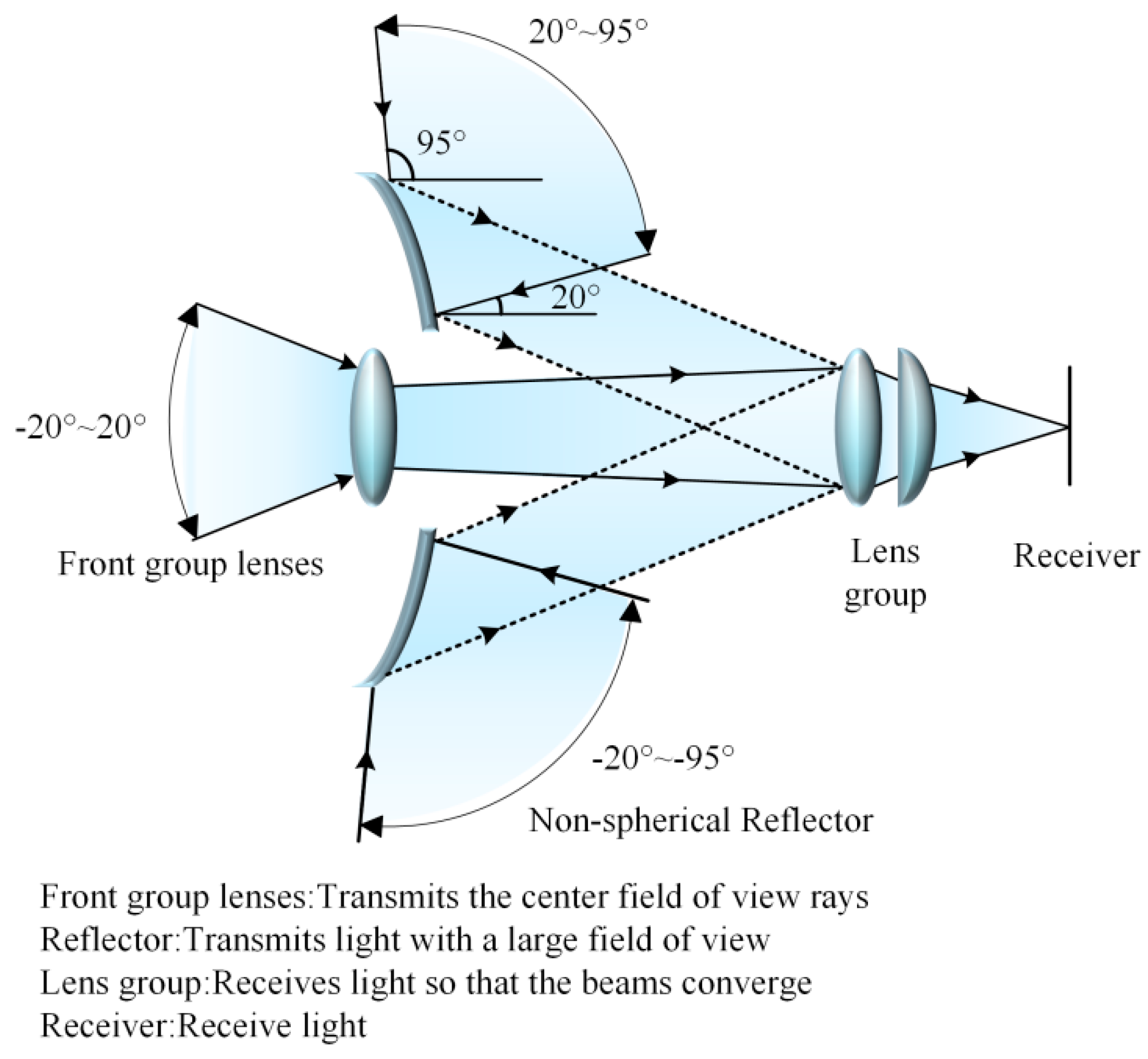
In the design of the large FoV optical system, a spliced structure is adopted. The compact dual-channel catadioptric panoramic imaging system, patented with CN 112363308 A, is selected as the reference structure. This structure is divided into an ultra-wide-field channel and a forward channel, with a full FoV of 130°. Based on this structural form and the associated parameter specifications, the FoV is further extended, resulting in the construction of two preliminary structures: Structure 1 with a full FoV ranging from 0° to 40° and Structure 2 with a full FoV ranging from 40° to 190°.
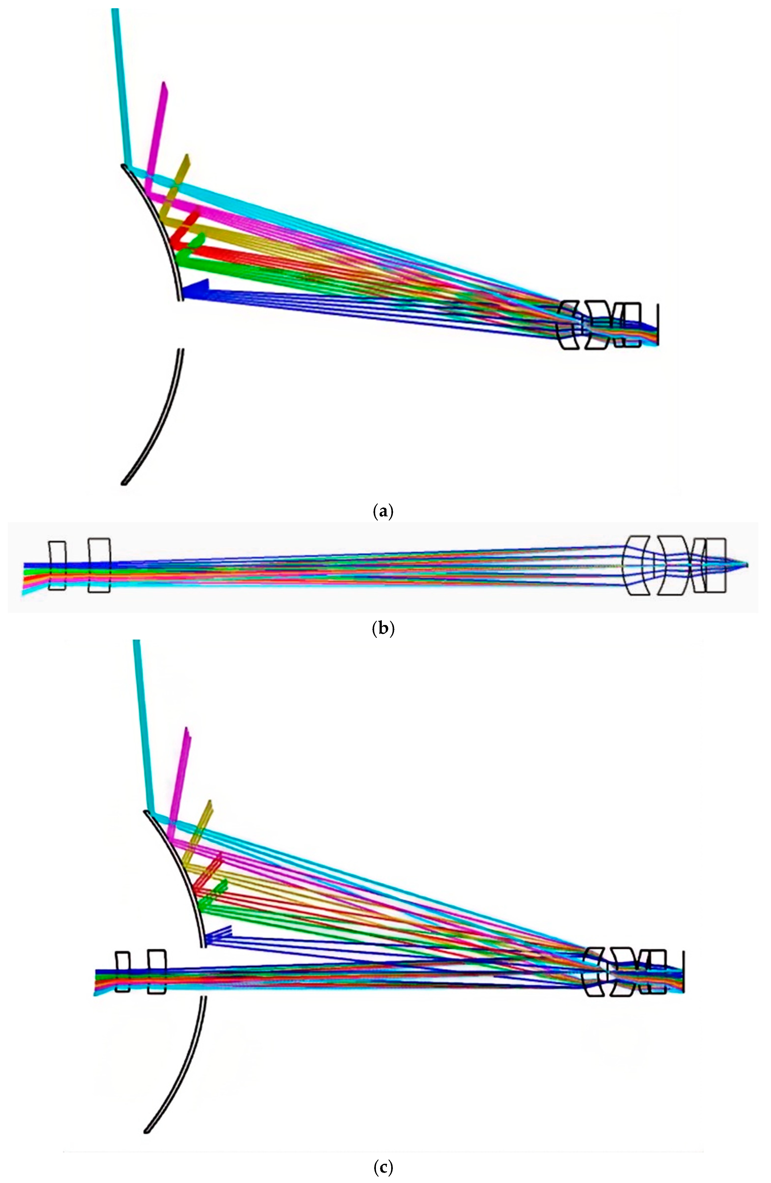
Using the ZEMAX optical design software, the effective tracing of the dual-channel optical path is achieved through gradual optimization of the structure. The final optical path diagram and optical parameters of the ultra-wide-field optical system are shown in
Figure 2 and
Table 2.
The even-order aspherical surface profile employed in the optical system can be expressed as follows [
12]:
where
z is the coordinate along the optical axis, r is the radial distance, c is the curvature, k is the conic constant, and
a1,
a2,
a3, and
a4 are the aspherical coefficients of the second, fourth, sixth, and eighth orders, respectively. The aspherical parameters are shown in
Table 3.
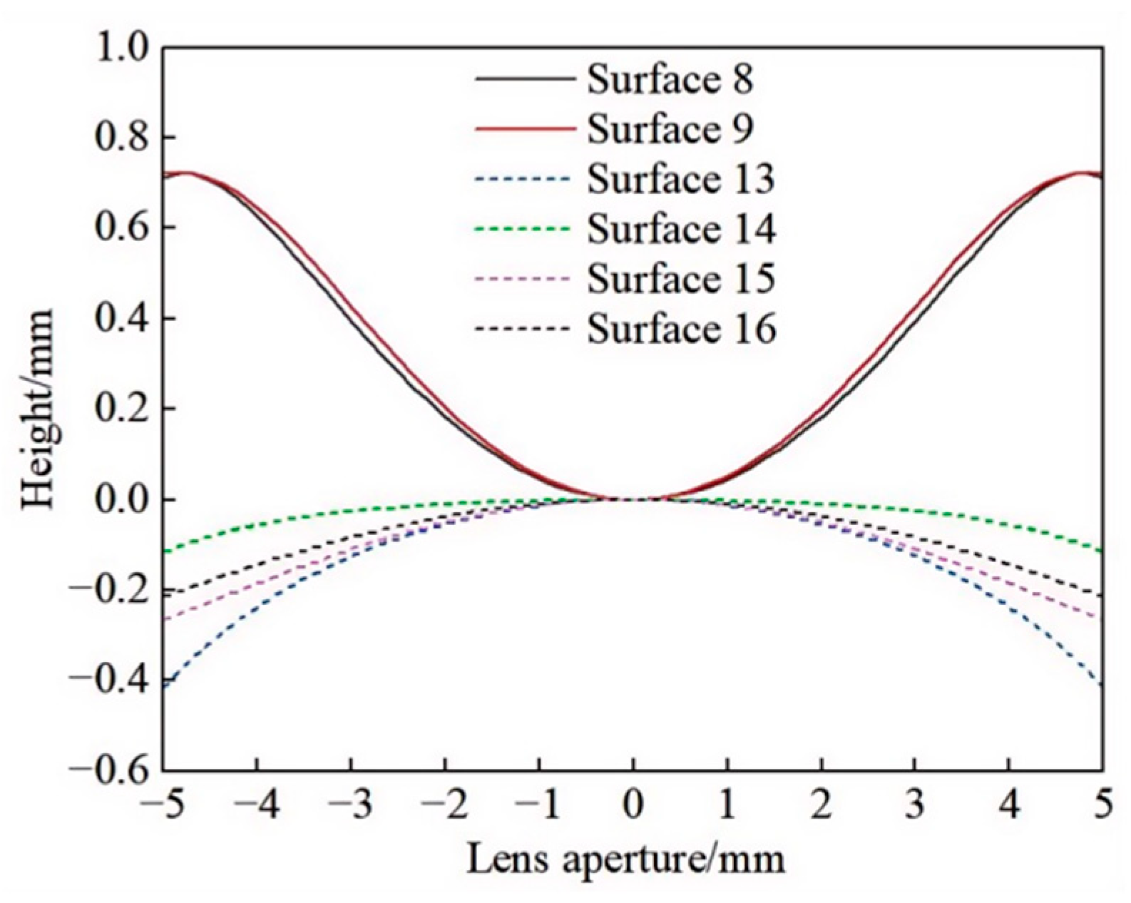
Based on the even-order aspherical surface parameters in
Table 3, simulation software was used to model the aspherical cross-sectional curve of the refractive system, with the results shown in
Figure 3.
As shown in
Table 3 and
Figure 3, the six even-order aspherical lens apertures employed in the system are appropriately sized, with the maximum order selected being the eighth-order coefficient. The curvature of the surface changes smoothly, without any abrupt transitions or discontinuities, thus meeting the manufacturing standards. Finally, after the design was completed, a flat lens was used in the system to coat a filter membrane, thereby reducing the impact of stray light on the final image quality of the detector.
3.2. Image Quality Evaluation
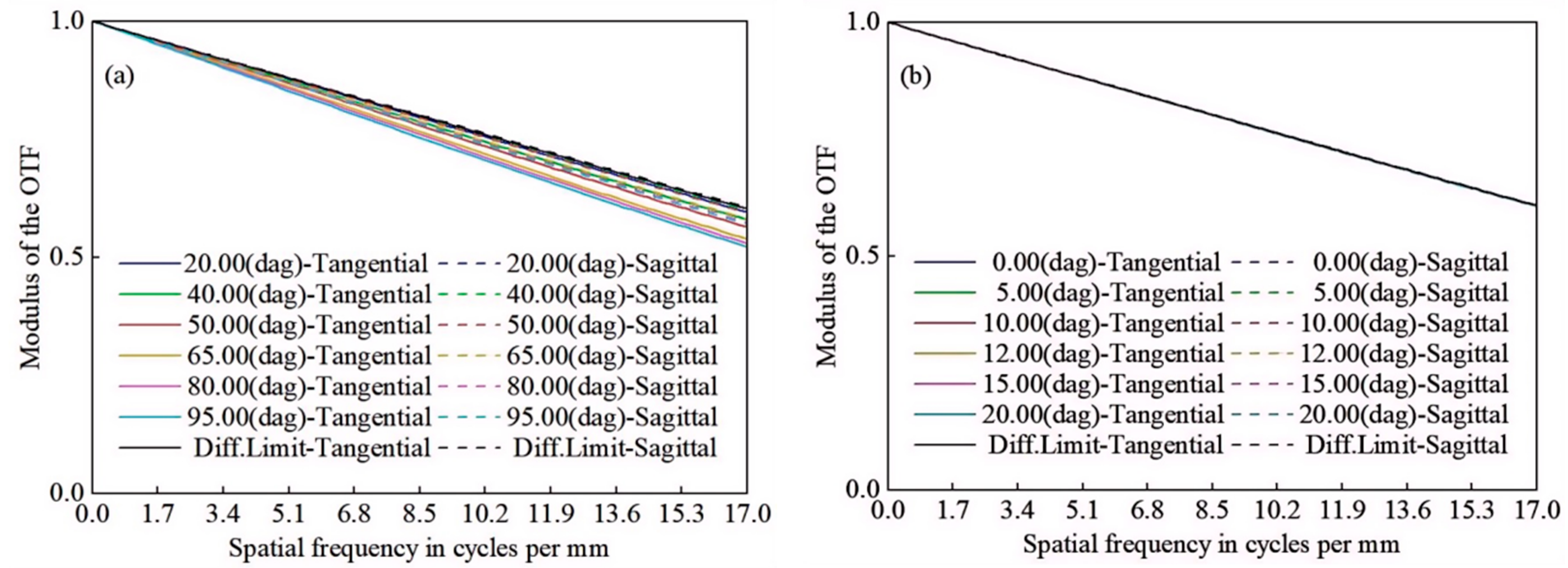
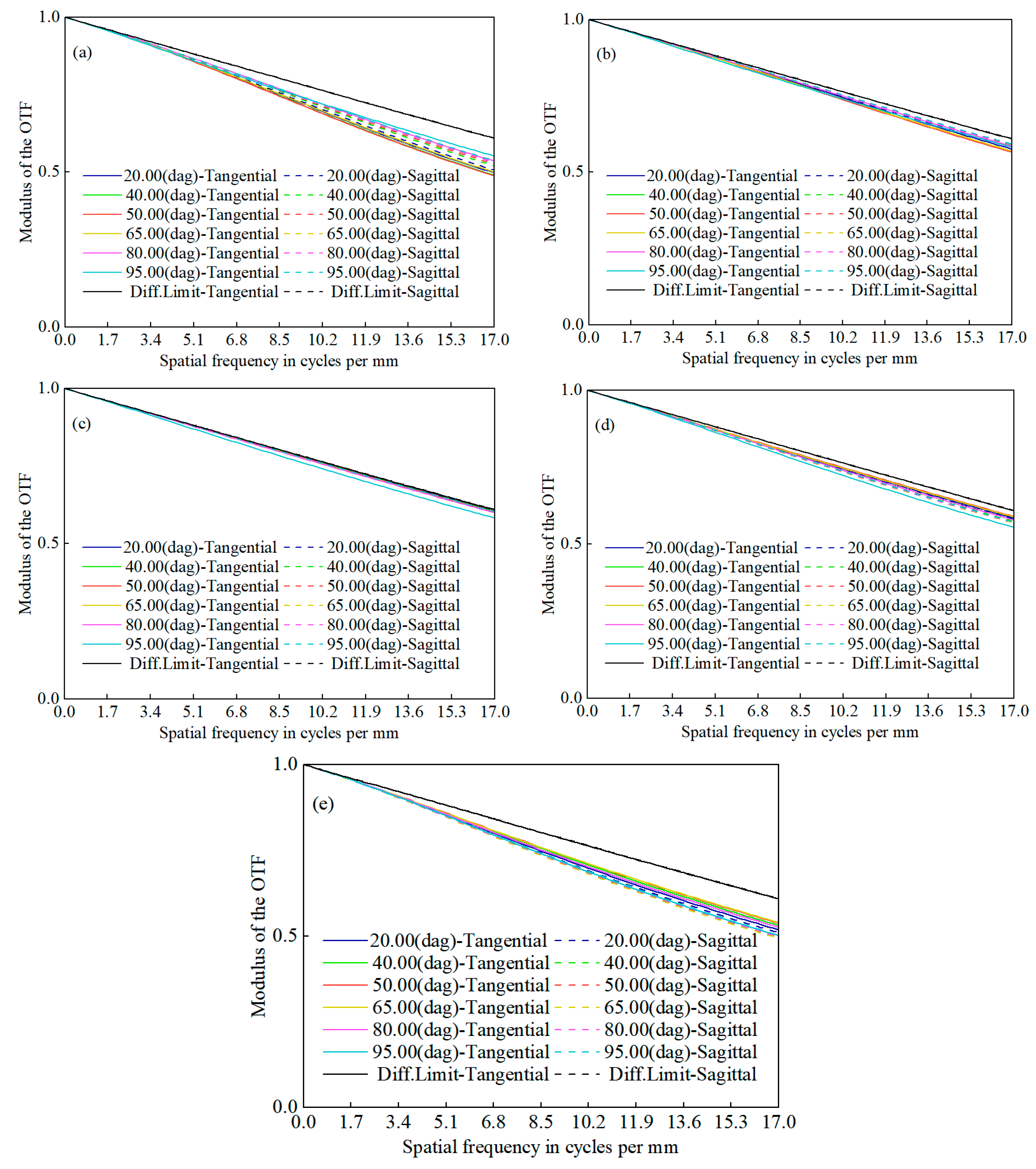
As illustrated in
Figure 4, the MTF curves for the forward channel and ultra-wide-field channel structures are presented. The system’s cutoff frequency is observed to be at 17 lp/mm. The MTF values for Structure 1 and Structure 2 are greater than 0.5 and 0.6, respectively, both exceeding 0.4. The smooth and compact nature of the curves indicates that the system maintains excellent imaging quality.
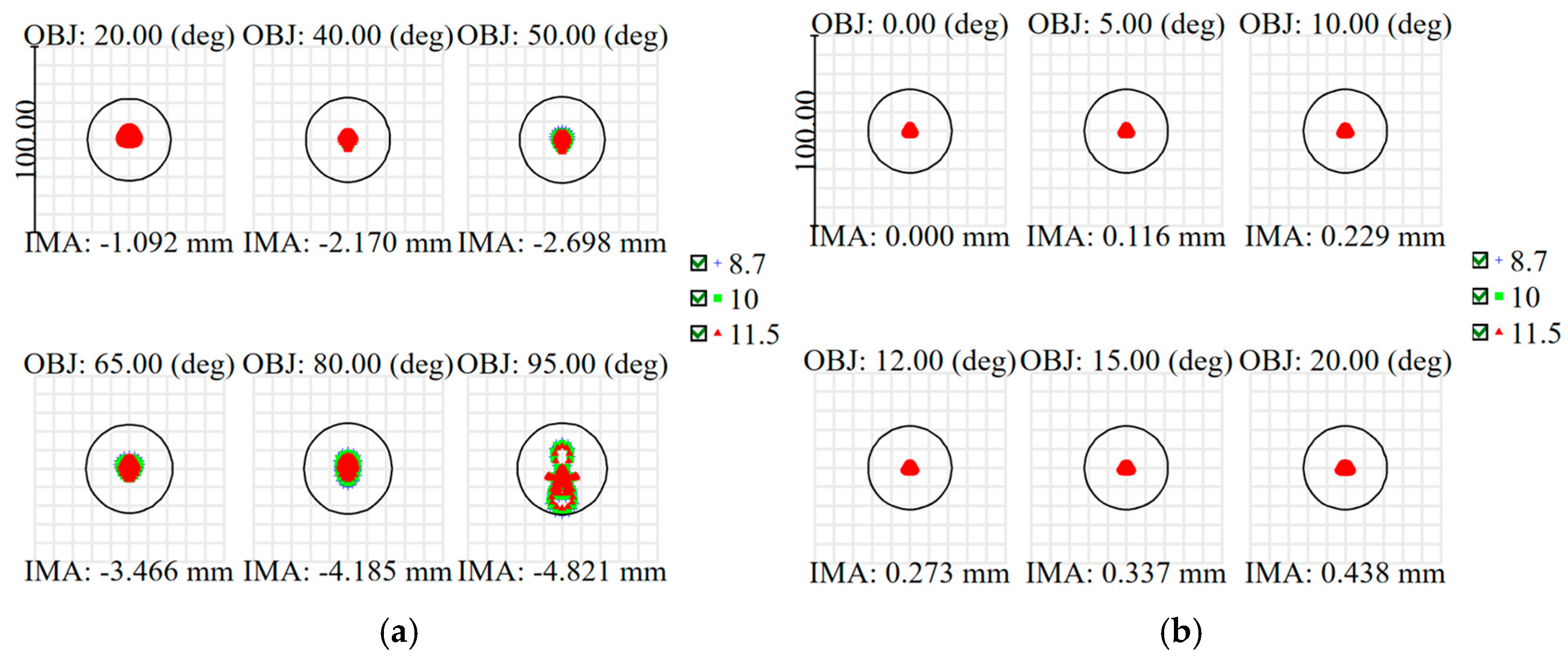
As depicted in
Figure 5, the system’s point spread function (PSF) is illustrated, with the RMS radii for both structures being within the airy disk radius (21.92 μm for Structure 1 and 21.93 μm for Structure 2) and the detector pixel size (30 μm). It is evident that the sizes of the diffraction spots across all wavelengths nearly overlap. Across the entire FoV both structures demonstrate exceptional optical performance.
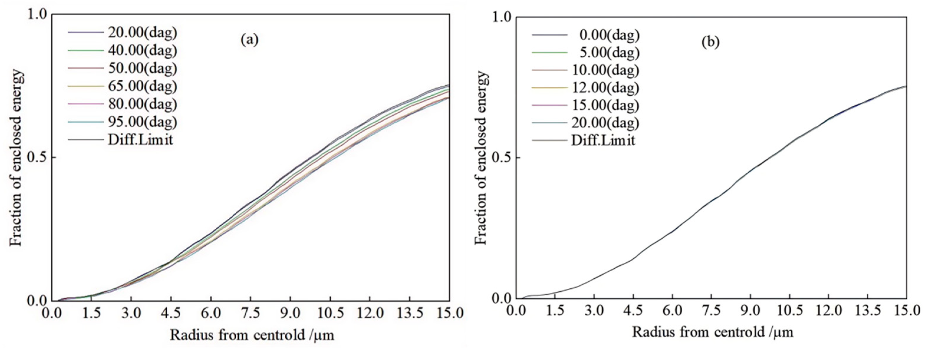
As depicted in
Figure 6, the energy convergence of the system is illustrated. The diffraction ring energy for both structures at a radius of 15 μm exceeds 60%, indicating efficient energy concentration and high optical performance.
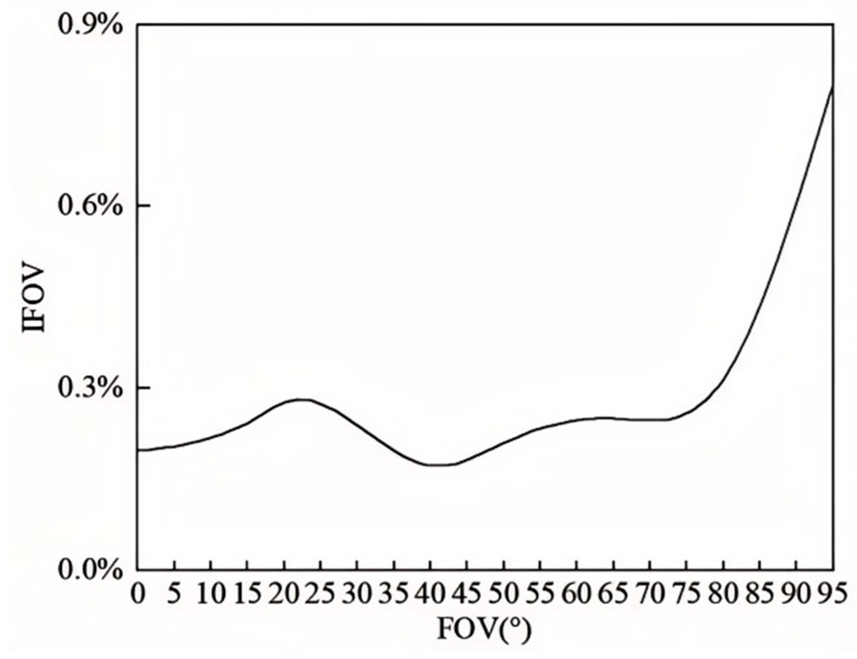
The capability of the infrared optical system to resolve details is measured using the instantaneous FoV (IFOV) non-uniformity. The smaller the value of the spatial resolution, the better the detection performance of the optical system. The calculation formula is given by the following:
where
l represents the image plane spacing of the optical system and
f represents the focal length of the optical system. Based on this, the IFOV for each FoV is calculated and plotted as a curve, as shown in
Figure 7. It can be observed that the maximum deviation of the angular resolution across the full FoV is within 0.9%, indicating that the optical system has excellent detail resolution capability.
3.3. Tolerance Analysis
To ensure the feasibility of practical engineering applications, a comprehensive tolerance analysis was conducted on the designed ultra-wide-field system, and the results of this analysis were used to validate the manufacturing and assembly processes [
13]. Set the initial tolerance data according to the tolerance level table in
Table 4, where Q1 to Q8 represent tolerance levels ranging from strict to loose. Starting from Q4, the corresponding values are entered into the default tolerance table for tolerance analysis. By examining the generated textual data, the primary tolerances that lead to unsatisfactory results are appropriately tightened. This process is repeated until the surface and component tolerance values for the system are determined, as shown in
Table 5 and
Table 6.
After establishing the tolerance thresholds, the efficiency tolerance analysis tool in ZEMAX software was employed to verify their rationality. To ensure the accuracy and persuasiveness of the assessment report, the MTF was selected as the evaluation criterion, and sensitivity analysis was chosen as the analysis mode. The precision of the results improves with the number of Monte Carlo runs, which was set to 200 in this case. The analysis results are shown in
Table 7.
It can be observed that under this tolerance setting, 90% of the images have an MTF greater than 0.4 at 17 lp/mm, indicating that the tolerance setting is reasonable.
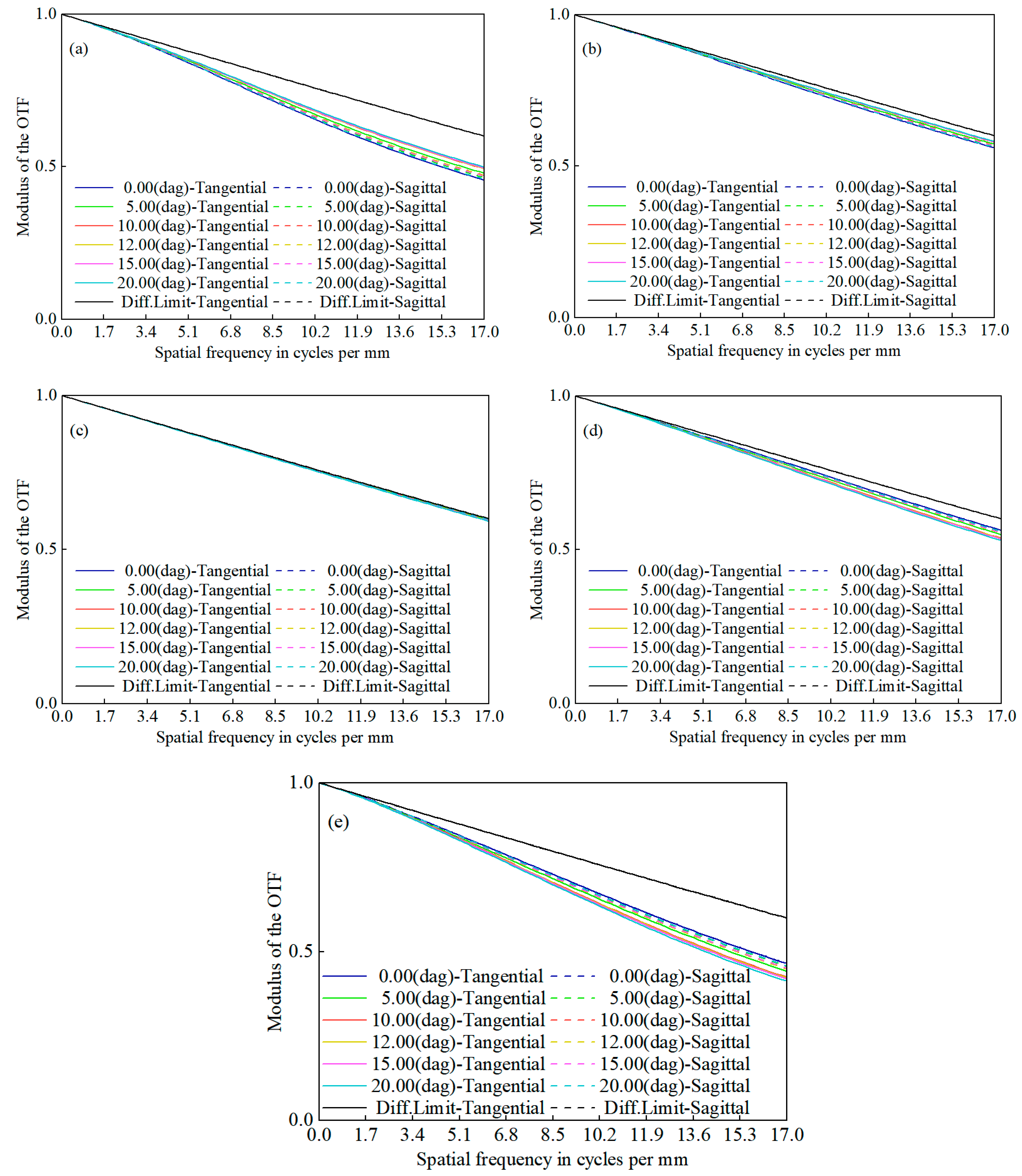
3.4. Thermalization Analysis
Finally, to meet practical application requirements, a thermal-insensitive design was implemented for the optical system within the temperature range of −20 °C to 60 °C. The process for thermal-insensitive design is as follows: ① Select multiple structures, create structures for different temperatures, set the thermal expansion coefficient of the lens barrel, and update the evaluation function. ② Choose appropriate parameters as variables and perform optimization. ③ Compare the results with system specifications, assess the outcome, and if the requirements are not met, repeat steps ② and ③. After completing the thermal-insensitive design, the MTF curves for Structure 1 and Structure 2 are presented in
Figure 8 and
Figure 9, respectively.
It is evident that while the optical system exhibits minor fluctuations across the entire temperature range, the overall performance at 17 lp/mm remains above the required specification of greater than 0.4. This consistent performance ensures good image quality and thus satisfies the system’s thermal-insensitive design requirements.
4. Discussion
Conventional ultra-wide-field systems, like fisheye and panoramic annular lenses, can achieve large fields of view but suffer from complex structures, high manufacturing difficulty, central field loss, or low energy efficiency. For example, Davide Greggio’s dual-focus panoramic lens achieves a 100° vertical field. Still, it is complex and difficult to manufacture [
14], while James B. Johnson’s multispectral annular lens simplifies the structure but still has blind spots [
15]. In contrast, this study uses field stitching technology to match the optical parameters of reflective and refractive channels precisely, eliminating blind spots and achieving efficient aberration correction and energy concentration with an all-Ge refractive path. The system achieves MTF > 0.5 at 17 lp/mm, with spot sizes controlled within the airy disk, resulting in better image quality. Regarding thermal adaptability, unlike existing infrared systems that rely on active temperature control or complex compensation mechanisms due to thermal expansion, this design employs a passive athermal approach. It maintains an MTF > 0.4 from −20 °C to 60 °C, simplifying the structure, reducing costs, and providing a feasible solution for practical applications in harsh environments.
The optical system designed in this study has significant application potential across various fields. In military reconnaissance, the 190° FoV combined with long-wave infrared all-weather detection enables large-scale battlefield monitoring and early warning, especially for covert surveillance in low-light or no-light environments. In industrial inspection and intelligent transportation, the system’s compactness and ultra-wide angle enhance machine vision’s perception range, enabling panoramic monitoring in complex production lines or traffic hubs. In astronomy, the ultra-wide FoV aids in capturing broad celestial phenomena, providing high-resolution data for studies on dark matter distribution or transient celestial bodies.
In summary, this design opens new paths for wide-field imaging needs in military, industrial, and research fields through its high performance, compactness, and cost-effectiveness. Future research can focus on expanding the FoV, environmental adaptability, and intelligent integration to further promote the practical and multifunctional development of ultra-wide-field optical systems.


