Article

Characteristics of Fused Silica Exit Surface Damage by Low-Temporal Coherence Light Irradiation

1
Shanghai Institute of Laser Plasma, China Academy of Engineering Physics, 1129 Chenjiashan Road, Shanghai 201800, China
2
State Key Laboratory of Functional Crystals and Devices, Shanghai Institute of Ceramics, Chinese Academy of Sciences, Shanghai 201899, China
3
College of Intelligent Science and Technology, National University of Defense Technology, Changsha 410073, China
4
Troops 91007, Chinese People’s Liberation Army, China
5
Key Laboratory of High-Power Laser Materials, Shanghai Institute of Optics and Fine Mechanics, Chinese Academy of Sciences, Shanghai 201800, China
*
Author to whom correspondence should be addressed.
Photonics 2025, 12(5), 432; https://doi.org/10.3390/photonics12050432
Submission received: 30 March 2025 / Revised: 19 April 2025 / Accepted: 27 April 2025 / Published: 30 April 2025
(This article belongs to the Special Issue New Perspectives in Micro-Nano Optical Design and Manufacturing)

Abstract

:
Laser-induced exit surface damage of fused silica is a key bottleneck for its application in high-power laser devices. As low-temporal coherence light (LTCL) has garnered increasing attention for high-power laser-driven inertial confinement fusion, understanding LTCL-induced exit surface damage of fused silica becomes crucial for improving the output power capability of LTCL devices. In this study, we characterized damage on the exit surface of fused silica under LTCL irradiation and investigated the physical mechanism of temporal coherence affecting the laser-induced damage threshold (LIDT). The relationship between defect information and temporal coherence was explored using a defect analysis model, and the defect damage process and response to each incident lasers were captured using time-resolved methods and artificially fabricated defects. We elucidate the physical mechanism behind the lower LIDT under LTCL irradiation compared to single longitudinal mode (SLM) pulse lasers. This study not only provides the boundary condition for safe fused silica operation in high-power LTCL devices but also offers deeper insight into the physical properties of LTCL.

1. Introduction

A positive fusion exergy output of 3.05 MJ at Livermore National Laboratory in the United States marks the successful “ignition” of laser inertial confinement [1,2]. The condition for achieving laser inertial confinement fusion (ICF) is very strict. The triple-frequency fluence irradiation on the terminal optical components has almost reached its safe operation limitation [3]. Fused silica has a wide range of applications in high-power laser devices due to its excellent optical, thermal, and mechanical properties [4,5,6]. Therefore, the issue of laser-induced fused silica damage is a bottleneck problem that restricts its application and even limits the laser output capability. In particular, laser-induced damage on the exit surface of fused silica is mainly caused by surface and sub-surface defects [7,8,9]. There is an electric field enhancement effect on the exit surface of fused silica during laser irradiation, resulting in a lower laser-induced damage threshold (LIDT) on the exit surface than on the input surface and bulk damage [8].
To mitigate the negative effects of laser plasma instability (LPI) and enable new ignition options, the low-temporal coherence light (LTCL) has garnered significant attention due to its characteristics, such as instantaneous broadband and random phase distribution [10,11,12,13,14]. Low-temporal coherence indicates a broadband pulse spectrum with a random spectral phase, also known as spectrally incoherent broadband pulses [15]. Such pulses, characterized by possession of both low-temporal coherence and instantaneous broadband properties, have the full spectral component in a time slice of the pulse coherence time scale [13]. These pulses could also be called low-temporal coherence light. In particular, recent experimental results demonstrate that LTCL can effectively suppress LPIs, such as stimulated Raman scattering, greatly enhancing ignition probability [16,17]. The LTCL has a broad bandwidth with a coherence time much shorter than the pulse duration, and its spectral phases are randomly and uniformly distributed, unlike those of chirped pulses. This matches the statistical properties of polarized thermal light. The LTCL can be viewed as an accumulation of many pulses, each with a duration close to the coherence time [11]. Nevertheless, laser-induced exit surface damage of fused silica upon LTCL irradiation poses a significant challenge for high-power LTCL device operation.
There has been extensive excellent research on the exit surface damage mechanisms of fused silica for conventional coherence light [18,19,20,21,22,23,24,25]. B.C. Stuart et al. modified the incident laser pulse width by changing the dispersive path length of a single-grating compressor. They determined the relationship between the LIDT of the exit surface and the incident pulse width, and established an analysis model to investigate multiphoton ionization effects [26,27]. Numerous studies also exist on the laser-induced damage characteristics for multiple longitudinal mode (MLM) pulse laser irradiation [28,29,30,31]. R. Diaz, et al. found that the laser-induced damage density on the surface of fused silica is higher for MLM pulse laser irradiation than for the single longitudinal mode (SLM) pulse laser at 1064 nm, and explained this by three-photon absorption by temporal spikes of the MLM pulse laser [29]. The LTCL has more complex spike structures than the MLM pulse laser, posing a greater threat to the fused silica surface’s damage resistance and complicating the physical mechanism of defect damage. However, the physical mechanism of LTCL-induced exit surface damage of fused silica and the effect of temporal coherence on the LIDT have not been reported. Therefore, investigating the exit surface damage characteristics of fused silica by LTCL irradiation is a significant priority for its application in high-power LTCL devices.
In this study, we characterized the pattern of temporal coherence affecting the LIDT on the exit surface of fused silica. Utilizing the defect analysis model and the time-resolved method, the defect information corresponding to each bandwidth of LTCLs is obtained. Through artificially fabricated defects, we explored the mechanism of temporal coherence affecting the absorption of the defects and the LIDTs on the exit surface of fused silica. This study not only investigates the effect of temporal coherence on the properties of the LIDT on the exit surface of fused silica but also provides reliable defect precursor information for improving the LTCL-induced damage threshold of fused silica.

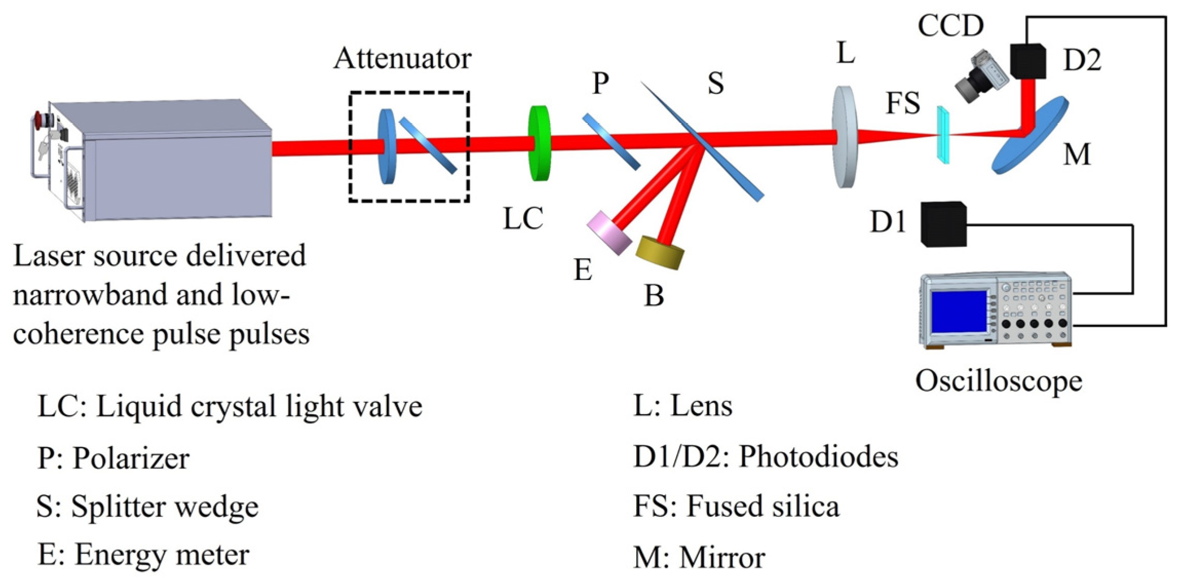
2. Experimental Details

Experimental Setup

In this study, a 40 mm × 40 mm × 3 mm fused silica wafer was used as the test sample. Both the input and exit surfaces were polished and acid washed to ensure the surface roughness and profile were maintained at 0.5 nm (RMS) and λ/4 (λ = 632.8 nm), respectively. The LIDT test setup for the exit surface of the fused silica sample is shown in Figure 1. The incident laser could produce either the SLM pulse laser or the LTCL with a wavelength center at 1053 nm. For the LTCL, the temporal coherence could be adjusted by controlling the spectral width of the incident laser, and the spectral full width at half-maximum (FWHMs) for the LIDT test were 3 nm, 8 nm, and 13 nm, respectively (Figure 2a). The central wavelengths of the SLM pulse laser, the LTCL (3 nm), the LTCL (8 nm), and the LTCL (13 nm) were 1053 nm, 1053 nm, 1062 nm, and 1058 nm, respectively. The difference in the central wavelength of each incident laser would affect the LIDT test results through differences in photon energy. However, based on the LIDT test result of fused silica described below, the difference in central wavelength has a lesser impact compared to the large differences in LIDT observed for each incident laser. The central wavelength effect on the LIDT for other optical materials would be analyzed in more detail in subsequent studies. The pulse duration of each incident laser was 3 ns (FWHM), as shown in Figure 2b.
The incident energy for each incident laser is controlled by an attenuator consisting of a half-wave plate and a polarizer. The original near fields of each incident laser were slightly different. To ensure the accuracy of the experimental test, a combination of liquid crystal light value and polarizer was applied to regulate the near field of each incident laser, which made the beam area and energy distribution remain uniform. Through 10 times tests, the size of each incident laser was kept at (10 ± 0.2) mm at 1/e2, and the near-field energy distribution of each incident laser was fitted with a Gaussian function to ensure that this energy distribution was strictly maintained as a Gaussian distribution, which ensured the consistency of the near field of each incident laser.
The incident laser energy and beam qualities are monitored by an energy meter and a beam quality analyzer, respectively. A lens with a focal length of 4.5 m focuses the beam (the beam effective area at the focal point of 0.45 mm2, and the incident laser fluence was equivalent to the incident laser energy divided by the effective area.), ensuring the Rayleigh length is longer than the sample thickness. Laser-induced surface damage of fused silica is recorded by a CCD camera on the side of the sample. Two InGaAs photodiodes, D1 and D2 (time resolution of 150 ps), connected to an oscilloscope sampling rate of 5 GHz, are placed on the side of the fused silica and in the direction of laser transmission for recording the damage process using the time-resolved method, and as the oscilloscope did not employ an interpolation algorithm, the overall temporal resolution of this time-resolved system was 200 ps. Invisible damage in fused silica was traditionally assessed by two methods: analyzing variations in the temporal waveform (recorded transmission signal by photodiodes) and the beam quality (recorded by a beam analyzer) during subsequent laser irradiation with low fluence after LIDT shots. If there was no variation in the temporal and spatial domains, it could be considered that no invisible damage had occurred. The LIDTs for each incident laser are tested using the 1-on-1 test method [32].

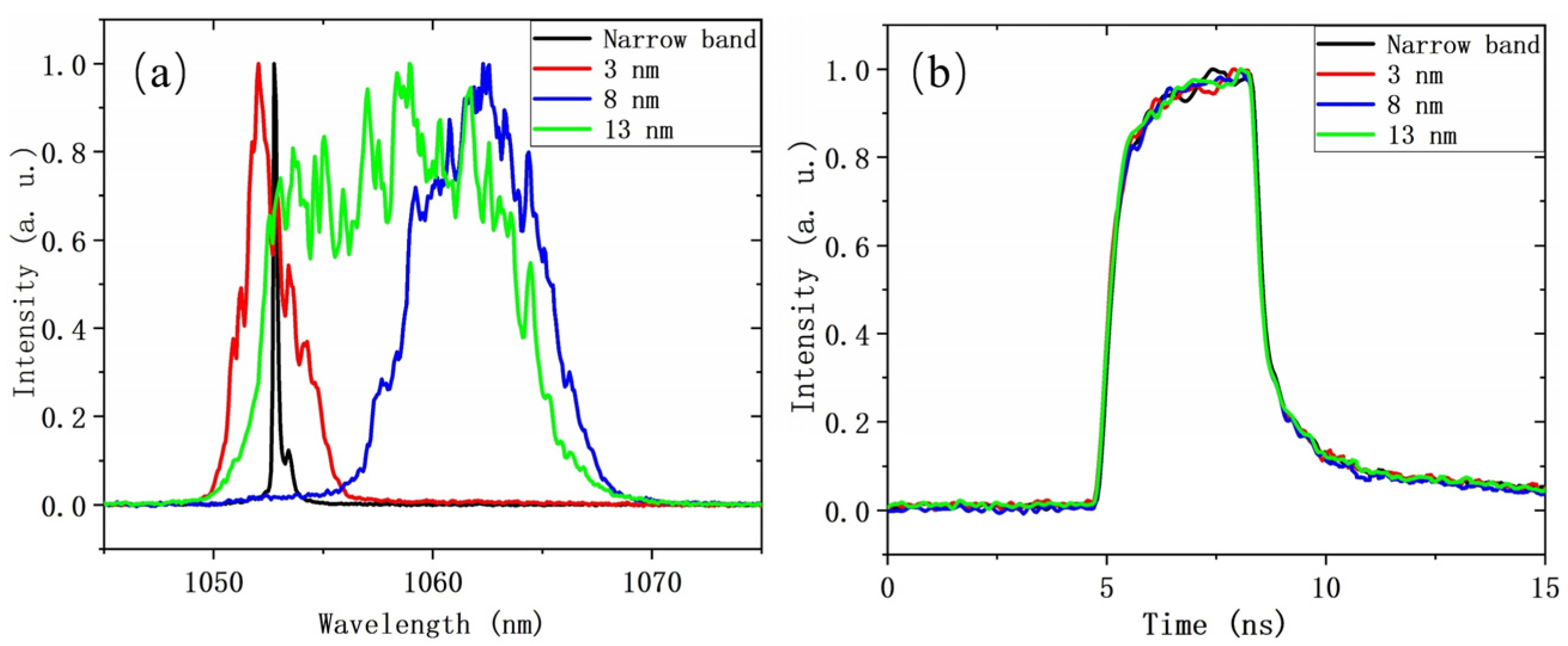
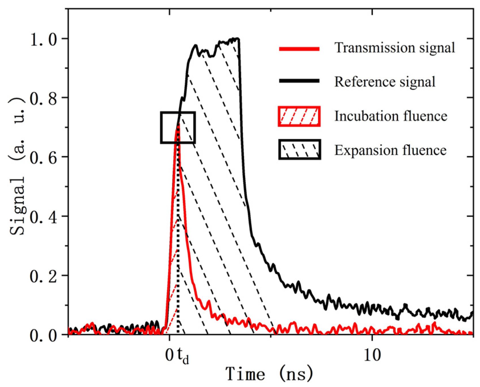
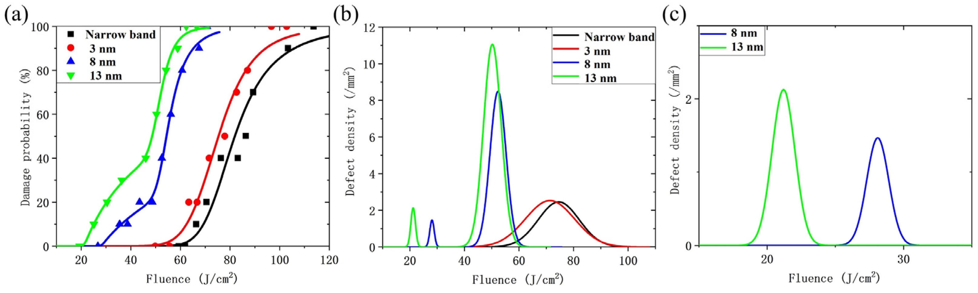
3. Experimental Results
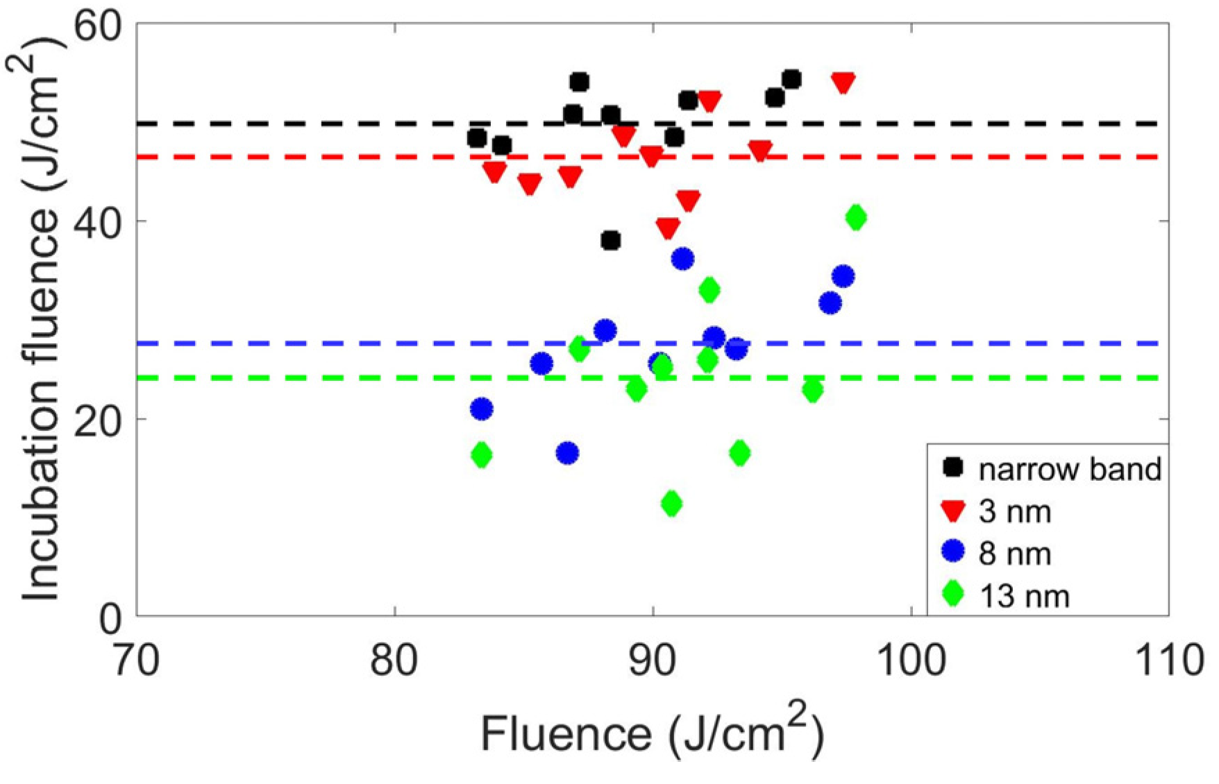
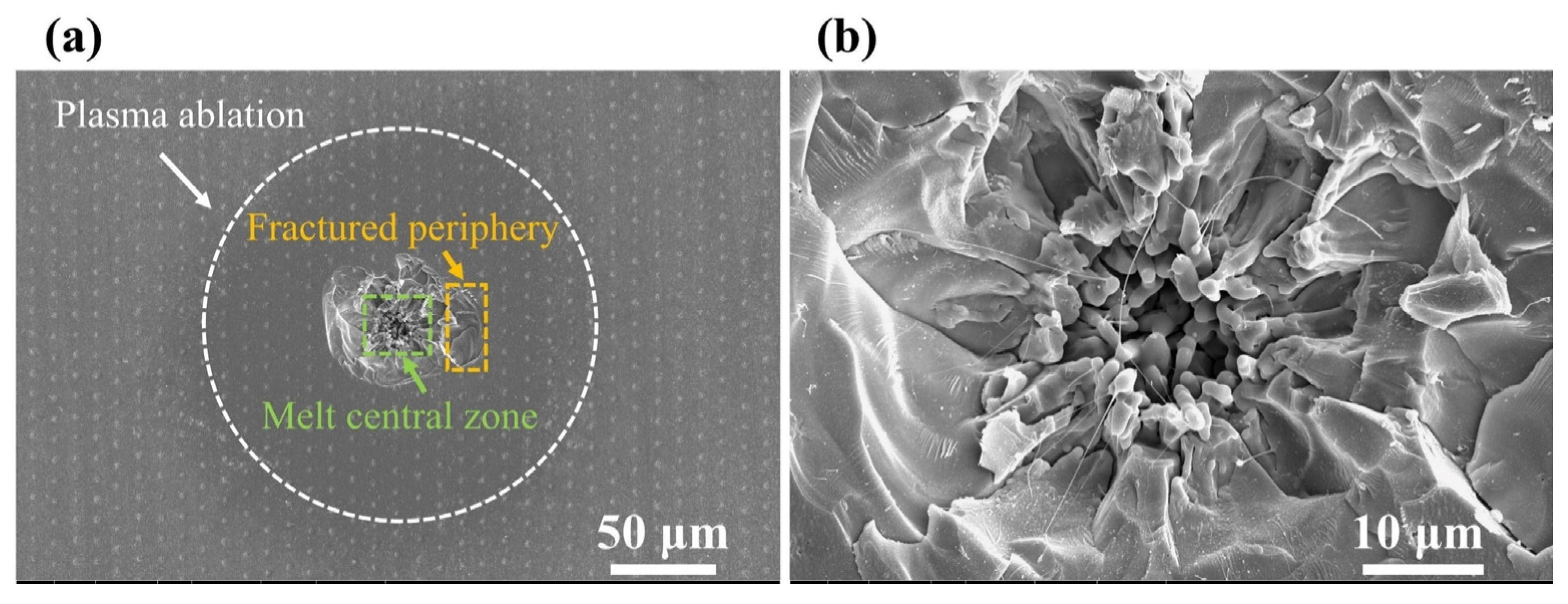
The LIDT test results for each incident laser are shown in Table 1. It is found that the LIDTs on the exit surface of fused silica for the LTCLs are lower than those of the SLM pulse laser, and for the LTCL, the LIDTs decrease with increasing bandwidth. The corresponding damage mechanisms will be analyzed in the following section.
The damage morphologies of the fused silica exit surface by LTCL irradiation were recorded using a Scanning Electron Microscope (SEM: FEI- versa 3d, Hillsboro, OR, USA). To demonstrate the damage morphology clearly, the laser irradiation was carried out with a fluence (86.63 J/cm2) much higher than the LIDT, as shown in Figure 3. It can be observed that the exit surface damage morphologies by LTCL irradiation are consistent with those of the conventional SLM pulsed laser [9], both of which consist of a melt central zone and a fractured periphery. The melt central zone is primarily caused by defect precursors on the fused silica surface and subsurface, which have a stronger absorption ability of incident laser energy compared to the fused silica substrate. As the defect precursor continuously absorbs laser energy, its temperature rises rapidly, and a melt central zone forms when the temperature reaches the melting point, presenting a relatively rough surface, as shown in Figure 3b. In the process of forming the melt central zone, temperature differences and corresponding thermal stresses are generated between the defect precursor and the surrounding fused silica substrate. These thermal stresses accumulate as the temperature of the defect precursor rises and ultimately remove material by mechanical stripping, presenting a smoother surface than the melt central zone, as shown in Figure 3c.
To obtain more defect damage information, we recorded the processes of laser-induced damage by the time-resolved method. Laser-induced surface damage is mainly divided into two damage phases: activation and expansion (as shown in Figure 4). The first phase is the incubation phase, mainly the process of defects on the surface or subsurface absorbing laser energy. When the absorption of laser energy exceeds the LIDT of the defect precursor and induced damage, the laser energy would be significantly absorbed and scattered by the defect damage, inducing a rapid decrease in the transmission signal. This is recorded by the photodiode ( D 2 ) in the transmission direction (transmission signal) as the damage time ( t d ) [24]. The second phase is the damage expansion process, which develops from the initial damage time ( t d ) to the end of the pulse. Therefore, the total incident fluence ( F t o t ) could be written as follows:
F t o t = F i n c + F e x p = I p e a k 0 t d f t d t + I p e a k t d + f t d t
where F t o t is the total fluence of incident laser, F i n c and F e x p represent the fluence absorbed by the defect precursors in the first process and the fluence required for the expansion of the damage in the second process, respectively. I p e a k and f ( t ) represent the incident peak intensity and a function of temporal waveform, respectively. We analyzed the defect precursor information of fused silica for each LTCLs by this method below.

4. Discussion

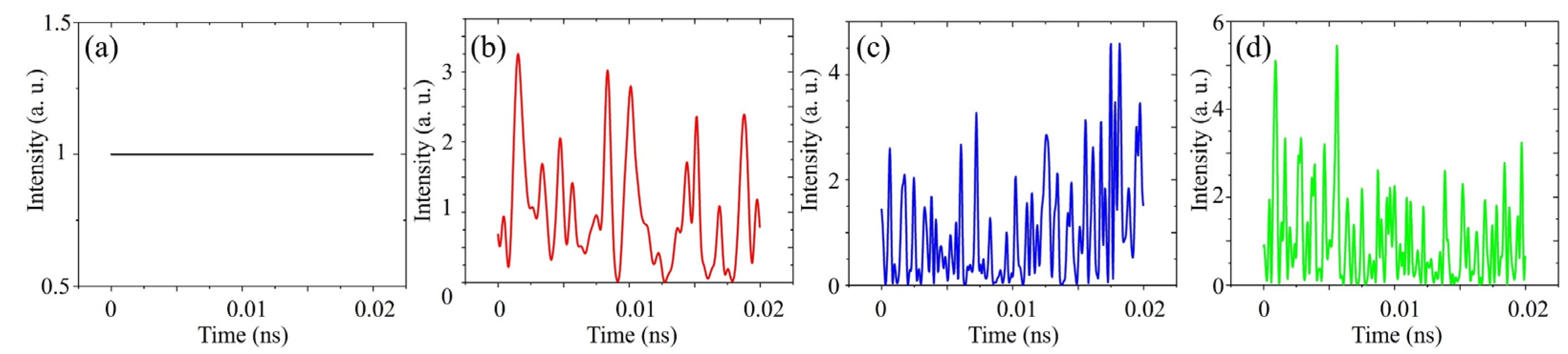
4.1. Temporal Spike Structure

The reduction of LIDTs for the LTCLs is caused by a combination of several factors. Firstly, the LTCL possesses a more complex temporal spike structure than that of the MLM pulse laser, as shown in Figure 5, and these temporal spike structures would be one of the important factors affecting the LIDTs. A. V. Smith et al. concluded that the reduction in the LIDT for the MLM pulse laser is directly related to the maximum intensity during the temporal spike structure [28]. For the LTCLs, the distribution of the temporal spike intensities for each bandwidth satisfied the negative exponential distribution [14]. The highest intensity of the temporal spikes should be consistent for each LTCL, which should result in the same LIDTs for different bandwidths and should be 1/10 of the SLM pulse laser. However, the LIDT test results of the LTCLs during our experiments did not show a significant decrease like that, and they were not consistent for each bandwidth. This indicates that the highest intensity of the temporal spikes was not influenced by the LIDT directly, and there were other physical mechanisms during the laser-induced damage.
Although the decrease in the LIDTs on the exit surface of fused silica is not directly induced by the highest intensity spikes for the LTCLs, the temporal spike structures also affect the LIDT test results by the multiphoton absorption and the accumulative effect. For the LTCLs, the spike structure in the temporal domain could be regarded as a series of pulse strings, and these multiple pulses present the cumulative effect, which would induce defects [33] and reduce the bandgap [34], which reduces the LIDTs of the fused silica [35]. The widths of the temporal spikes for the LTCLs are roughly 280 fs, 460 fs, and 1.25 ps, corresponding to the bandwidth of 13 nm, 8 nm, and 3 nm, respectively. (Since the experimental time-resolved setup was unable to capture the temporal spike widths of the LTCL with different bandwidths, these widths were obtained through theoretical calculations based on statistical properties of the LTCLs and the Fourier transform of their spectra.) This implies that the wider the bandwidth, the smaller the duration of the spikes, and the corresponding number of the spikes and the repetition frequency of the pulse train would be increased at the same duration of the incident pulse, which leads to a more significant decrease in the LIDTs of the fused silica [36]. It also verifies the previous speculation about why the MLM pulse laser decreased the LIDT of SiO2 [37].
Meanwhile, due to the large bandgap of fused silica (approximately 9 eV) [38], multiphoton absorption with a fundamental frequency laser (1.17 eV) is improbable for the incident intensities involved in this paper. However, sub-bandgap photons might be absorbed by subsurface atomic-scale defects [39]. The strong photoluminescence under 3.5 eV excitation [39,40] is consistent with three-photon absorption of the fundamental frequency laser. It could be deduced that the LTCL, with temporal spike structures similar to the MLM pulse laser, would reduce the LIDT of fused silica through the multiphoton absorption effect. As mentioned above, the number of high-intensity temporal spikes increases with the bandwidth for the same pulse duration, promoting multiphoton absorption and further decreasing the LIDT, consistent with the relationship of the LIDT of LTCLs with different bandwidths. It was worth noting that the LIDT test results, as shown in Table 1, indicate that the difference between the LTCL (3 nm) and the SLM-pulsed laser is not significant. It is considered that there were relatively few temporal spike structures for the LTCL (3 nm) due to its large temporal spike durations; thus, nonlinear absorption effects, such as three-photon absorption, would not be effectively amplified. However, the LIDT of LTCL (8 nm) shows a significant decrease compared to LTCL (3 nm), suggesting that the multiphoton absorption effect has begun to dominate and affect the LIDT test results at this point.

4.2. Defect Precursor Information

Laser-induced surface damage of fused silica is primarily caused by defect precursors on the surface or sub-surface. Consequently, the different information of the defect precursors corresponding to the LTCLs and SLM pulse laser would also be a critical factor for influencing the LIDT test results. To study the effect of temporal coherence on defect precursors, a statistical model is assumed where the probability of a defect precursor absorbing higher fluence than its intrinsic damage threshold follows the Poisson law [41,42,43,44]. The damage probability related to the average number of defect precursors, N F , can be expressed as follows:
P F = 1 e x p N F
where N F is the number of defect precursors in the beam spot with an intrinsic damage threshold below F :
N F = 0 F g T · V T F d T
The defect precursor distribution typically could be assumed to satisfy the Gaussian fluence distribution with a mean threshold fluence T 0 , a standard deviation Δ T (full width at 1/e2), and defect precursor density [43,44]. The ensemble function g T could be expressed as follows:
g T = 2 n 0 Δ T 2 π exp 1 2 T T 0 Δ T 2 2 0 g T d T = n 0
The efficient volume S T F where the fluence F is higher than the intrinsic damage threshold of the defect precursor could be expressed as follows:
S T F = S e f f l n F T
where the S e f f is the effective area of the incident laser beam. The correlation best-fit curves using the model with a coefficient of the determination R 2 of 0.92–0.95 are shown in Figure 6, and the defect precursors information on the exit surface of fused silica for each incident lasers are listed in Table 2. Parameters of this distribution (defect precursor densities ( n 0 ), threshold mean value ( T 0 ) and threshold standard deviation ( Δ T ) could be obtained clearly.
It was found that only one kind of defect precursor was observed for both the SLM pulse laser and LTCL (3 nm). The defect density ( n 0 ) of the LTCL (3 nm) was higher than that of the SLM pulse laser, the corresponding threshold mean value ( T 0 ) for the LTCL (3 nm) was lower than that of the SLM pulse laser, and the threshold standard deviation ( Δ T ) of the LTCL (3 nm) had a larger distribution than that of the SLM pulse laser. This indicates that the LTCL (3 nm) corresponds to a wider variety of defect precursors (different sizes and depths from the surface) and a greater number of precursors on the fused silica surface than the SLM pulse laser, with a lower average threshold. For the LTCL (8 nm) and LTCL (13 nm), defect information at a high damage probability was similar to the LTCL (3 nm) and the SLM pulse laser, but a new type of defect appeared at a low damage probability. It was mainly caused by the fact that the temporal spike structure widths of the LTCL (8 nm) and LTCL (13 nm) were 460 fs and 280 fs, respectively, containing a much larger number of temporal spike structures with high peak intensity than the LTCL (3 nm) and SLM pulsed laser. This led to defect damage with strong absorption properties under low fluence irradiation, inducing a new type of defect damage information. The pattern of defect information aligned with LIDT test results, i.e., a wider bandwidth for the LTCL correlated with a higher defect density and lower average defect threshold.
To verify the accuracy of the analytical model for describing defect precursors, the time-resolved method was utilized to confirm the relationship between the average thresholds of the defect precursors corresponding to each incident laser. The incident laser fluence was applied between 80 and 120 J/cm2 for the test irradiation of 20 points. The incubation fluence ( F i n c ) and expansion fluence ( F e x p ) were determined by recording the initial damage time ( t d ) as described above. The experimental results are presented in Figure 7.
It was concluded that the average value of incubation fluence ( F i n c ) of the LTCL is lower than that of the SLM pulse laser, and the distribution of the incubation fluence ( F i n c ) is wider for the same range of total incident fluence. As mentioned above, the damage size is related to the expansion fluence ( F e x p ), while the incubation fluence ( F i n c ) is associated with the defects’ properties. These differences are consistent with the relationship between the average defect damage threshold ( T 0 ) difference obtained by utilizing the defect analysis model as described above, which verified the accuracy of the defect analysis model for characterizing the defect precursor information of the LTCLs.

4.3. Artificially Prepared Defect Precursor

Finally, it is considered that the LTCLs and SLM pulse laser have different absorptions for the same defect precursors, which also induced a decrease in the LIDT of the LTCL. To objectively represent the response of different incident lasers to the same defect precursors, artificial fabrication of the same defect precursors was performed for each incident laser. Due to the random distribution of defect precursor types and damage thresholds on the fused silica surface, it was difficult to find precursors with identical sizes and depths. Femtosecond lasers have been applied extensively due to their ultra-short and ultra-intense properties, such as in meta-surface preparation [45,46]. Here, pit defect precursors were prepared using a femtosecond laser to investigate the difference in absorption and damage threshold between the LTCLs and SLM pulse lasers.
The pit defects prepared by femtosecond laser were observed by SEM and FIB, as shown in Figure 8. Each pit is spaced 10 μm and 5 μm apart, respectively (as shown in Figure 8a). Their diameters and depths are 2.43 μm and 0.6 μm, respectively (as shown in Figure 8c). These artificially prepared pit defects have excellent consistency. It is worth noting that to amplify the difference in the absorption and response of each incident laser for the same defect precursors, and more easily compare the damage processes of the different lasers inducing the same defect damage, the initial defect size and depth prepared in this chapter were slightly larger than those introduced by conventional machining [39]. The simulation results for defect information (as shown in Table 2) indicated that LTCLs were more sensitive to defects with low damage thresholds. Therefore, it was considered that artificially prepared defects would be larger than typical natural precursors, corresponding to stronger absorption properties. This would amplify the LIDT difference between the LTCLs and the SLM pulsed laser.
The pit defects were irradiated by each incident laser, and the defect damage morphology is shown in Figure 9. The pit damage morphologies consist of a melt central zone, a fractured periphery, and plasma ablation. The damage process and mechanism of the melt central zone and fractured periphery have been described above. For the plasma ablation area, it was mainly caused by the stronger absorption properties of the artificially prepared pit defects compared to the clean fused silica surface. Thus, the plasma generated during surface damage would expand outwards continuously, eventually forming the plasma ablation damage.
The International LIDT Test Standard (ISO 21254) defines laser-induced damage in optical components as irreversible changes after laser irradiation, considered as laser-induced component damage. In this chapter, three damage morphologies—melt central zone, fractured periphery, and plasma ablation—were observed for artificially prepared defects upon laser irradiation, with corresponding damage processes and mechanisms described in the original manuscript. Therefore, using three material variations as criteria, the incident fluence for each laser was adjusted to determine the fluence at which pit defects did not produce a melt central zone, fractured periphery, and plasma ablation simultaneously, which was set as the LIDT of the pit defects. Test results are shown in Table 3. For the same defect precursors, the LIDTs for the LTCLs are lower than for the SLM pulse laser. For the LTCLs, a broader bandwidth corresponds to a more significant decrease in the LIDTs of pit defects. This indicates that LTCLs have a stronger reaction to the same defects than the SLM pulse laser, one of the main reasons for the difference in LIDTs between the LTCL and SLM pulse laser.

5. Conclusions

In this paper, we systematically investigate the laser-induced damage characteristics on the exit surface of fused silica under LTCL irradiation. The test results suggest that the LIDTs of the LTCLs are lower than those of the SLM pulse laser, and for the LTCLs, the broader the bandwidth, the lower the LIDTs. Then, we analyzed the physical mechanism of the LIDT reduction for the LTCLs, concluding it is not directly caused by the maximum intensity of the temporal spike structure, but instead by multiphoton absorption and the cumulative effect of multiple pulses generated by the temporal spike structure. Analysis of defect density, average defect damage threshold, and defect threshold distribution also indicates larger differences in defect precursor information for LTCLs compared to SLM pulse lasers, contributing to decreased LIDTs. Finally, the different LIDTs of the artificially prepared pit defects precursor reveal that the LTCLs exhibit stronger absorption and response compared to the SLM pulse laser, also inducing a lower LIDT on the fused silica surface. This paper derives the characteristics and physical mechanism of the LTCL-induced fused silica surface damage and provides assistance in the investigation of the temporal coherence affecting the laser-induced damage mechanisms.

Author Contributions

Conceptualization, C.S. and P.H.; methodology, E.W.; software, F.L. and E.W.; validation, C.S., X.Z., H.K. and D.J.; formal analysis, X.P. and Q.W.; investigation, C.S. and Y.L.; resources, P.X., Y.Z., L.S., Z.S. and Y.G.; data curation, C.S. and P.H.; writing—original draft preparation, C.S.; writing—review and editing, X.Z. and F.L.; visualization, E.W. and F.L.; supervision, X.Z.; project administration, P.X. and Z.S.; funding acquisition, L.S., Y.G. and Z.S. All authors have read and agreed to the published version of the manuscript.

Funding

This research was supported by the National Natural Science Foundation of China (52450255).

Institutional Review Board Statement

Not applicable.

Informed Consent Statement

Not applicable.

Data Availability Statement

Data underlying the results presented in this paper are not publicly available at this time but may be obtained from the authors upon reasonable request.

Conflicts of Interest

The authors declare no conflicts of interest.

References

  1. Clery, D. Explosion marks laser fusion breakthrough. Science 2022, 378, 1154–1155. [Google Scholar] [CrossRef] [PubMed]
  2. Tollefson, J.; Gibney, E. Nuclear-Fusion Lab Achieves ‘Ignition’: What Does It Mean? Nature 2022, 612, 597–598. [Google Scholar] [CrossRef] [PubMed]
  3. Manes, K.R.; Spaeth, M.L.; Adams, J.J.; Bowers, M.W.; Bude, J.D.; Carr, C.W.; Conder, A.D.; Cross, D.A.; Demos, S.G.; Di Nicola, J.M.G.; et al. Damage Mechanisms Avoided or Managed for NIF Large Optics. Fusion Sci. Technol. 2016, 1, 146–249. [Google Scholar] [CrossRef]
  4. Miquel, J.-L.; Lion, C.; Vivini, P. The laser mega-Joule: LMJ & PETAL status and program overview. J. Phys. Conf. Ser. 2016, 688, 012067. [Google Scholar]
  5. Zheng, W.; Wei, X.; Zhu, Q.; Jing, F.; Hu, D.; Yuan, X.; Dai, W.; Zhou, W.; Wang, F.; Xu, D.; et al. Laser performance upgrade for precise ICF experiment in SG-III laser facility. Matter Radiat. Extrem. 2017, 2, 243–255. [Google Scholar] [CrossRef]
  6. Aikens, D.M.; Bissinger, H.D. Overview of small optics for the National Ignition Facility. In Optical Manufacturing and Testing III; SPIE: Bellingham, WA, USA, 1999; Volume 3782, pp. 476–487. [Google Scholar]
  7. Camp, D.W.; Kozlowski, M.R.; Sheehan, L.M.; Nichols, M.A.; Dovik, M.; Raether, R.G.; Thomas, I.M. Subsurface damage and polishing compound affect the 355-nm laser damage threshold of fused silica surfaces. In Laser-Induced Damage in Optical Materials; SPIE: Bellingham, WA, USA, 1998; Volume 3244, pp. 356–364. [Google Scholar]
  8. Tesar, A.A.; Brown, N.J.; Taylor, J.R.; Stolz, C.J. Subsurface polishing damage of fused silica: Nature and effect on laser damage of coated surfaces. In Laser-Induced Damage in Optical Materials; SPIE: Bellingham, WA, USA, 1991; Volume 1441, pp. 154–172. [Google Scholar]
  9. Bude, J.; Miller, P.; Baxamusa, S.; Shen, N.; Laurence, T.; Steele, W.; Suratwala, T.; Wong, L.; Carr, W.; Cross, D.; et al. High fluence laser damage precursors and their mitigation in fused silica. Opt. Express 2014, 22, 5839–5851. [Google Scholar] [CrossRef]
  10. Bates, J.W.; Myatt, J.F.; Shaw, J.G.; Follett, R.K.; Weaver, J.L.; Lehmberg, R.H.; Obenschain, S.P. Mitigation of cross-beam energy transfer in inertial-confinement-fusion plasmas with enhanced laser bandwidth. Phys. Rev. E 2018, 97, 061202. [Google Scholar] [CrossRef]
  11. Cui, Y.; Gao, Y.; Rao, D.; Liu, D.; Li, F.; Ji, L.; Shi, H.; Liu, J.; Zhao, X.; Feng, W.; et al. High-energy low-temporal-coherence instantaneous broadband pulse system. Opt. Lett. 2019, 44, 2859. [Google Scholar] [CrossRef]
  12. Gao, Y.-Q.; Ji, L.; Zhao, X.; Cui, Y.; Rao, D.; Feng, W.; Xia, L.; Liu, D.; Wang, T.; Shi, H.; et al. High-power, low-coherence laser driver facility. Opt. Lett. 2020, 45, 6839–6842. [Google Scholar] [CrossRef]
  13. Ji, L.; Zhao, X.; Liu, D.; Gao, Y.; Cui, Y.; Rao, D.; Feng, W.; Li, F.; Shi, H.; Liu, J.; et al. High-efficiency second-harmonic generation of low-temporal-coherent light pulse. Opt. Lett. 2019, 44, 4359–4362. [Google Scholar] [CrossRef]
  14. Zhao, X.; Ji, L.; Liu, D.; Gao, Y.; Rao, D.; Cui, Y.; Feng, W.; Li, F.; Shi, H.; Shan, C.; et al. Second-harmonic generation of temporally low-coherence light. APL Photonics 2020, 5, 091301. [Google Scholar] [CrossRef]
  15. Dorrer, C.; Hill, E.M.; Zuegel, J.D. High-energy parametric amplification of spectrally incoherent broadband pulses. Opt. Express 2020, 28, 451–471. [Google Scholar] [CrossRef]
  16. Lei, A.; Kang, N.; Zhao, Y.; Liu, H.; An, H.; Xiong, J.; Wang, R.; Xie, Z.; Tu, Y.; Xu, G.; et al. Reduction of Backward Scatterings at the Low-Coherence Kunwu Laser Facility. Phy. Rev. Lett. 2024, 132, 035102. [Google Scholar] [CrossRef]
  17. Wang, P.P.; An, H.H.; Fang, Z.H.; Xiong, J.; Xie, Z.Y.; Wang, C.; He, Z.Y.; Jia, G.; Wang, R.R.; Zheng, S. Backward scattering of laser plasma interactions from hundreds-of-joules broadband laser on thick target. Matter Radiat. Extrem. 2024, 9, 015602. [Google Scholar] [CrossRef]
  18. Crisp, M.D.; Boling, N.L.; Dube, G. Importance of Fresnel reflections in laser surface damage of transparent dielectrics. Appl. Phys. Lett. 1972, 21, 364–366. [Google Scholar] [CrossRef]
  19. Laurence, T.A.; Bude, J.D.; Ly, S.; Shen, N.; Feit, M.D. Extracting the distribution of laser damage precursors on fused silica surfaces for 351 nm, 3 ns laser pulses at high fluences (20–150 J/cm2). Opt. Express 2012, 20, 11561–11573. [Google Scholar] [CrossRef] [PubMed]
  20. Sun, L.; Liu, H.; Huang, J.; Ye, X.; Xia, H.; Li, Q.; Jiang, X.; Wu, W.; Yang, L.; Zheng, W. Reaction ion etching process for improving laser damage resistance of fused silica optical surface. Opt. Express 2016, 24, 199–211. [Google Scholar] [CrossRef] [PubMed]
  21. Lia, B.; Hou, C.; Tian, C.; Guo, J.; Xiang, X.; Jiang, X.; Wang, H.; Liao, W.; Yuan, X.; Jiang, X.; et al. Layer by layer exposure of subsurface defects and laser-induced damage mechanism of fused silica. Appl. Surf. Sci 2020, 508, 145186. [Google Scholar] [CrossRef]
  22. Carr, C.W.; Trenholme, J.B.; Spaeth, M.L. Effect of temporal pulse shape on optical damage. Appl. Phys. Lett. 2007, 90, 041110. [Google Scholar] [CrossRef]
  23. Palmier, S.; Gallais, L.; Commandre, M.; Cormont, P.; Courchinoux, R.; Lamaigne, L.; Rullier, J.L.; Legros, P. Optimization of a laser mitigation process in damaged fused silica. Appl. Surf. Sci. 2009, 255, 5532–5536. [Google Scholar] [CrossRef]
  24. Xu, Y.; Emmert, L.A.; Rudolph, W. Spatio-TEmporally REsolved Optical Laser Induced Damage (STEREO LID) technique for material characterization. Opt. Lett. 2015, 23, 21607–21614. [Google Scholar] [CrossRef]
  25. Miller, P.E.; Suratwala, T.I.; Bude, J.D.; Laurence, T.A.; Shen, N.; Steele, W.A.; Feit, M.D.; Menapace, J.A.; Wong, L.L. Laser damage precursors in fused silica. In Laser-Induced Damage in Optical Materials; SPIE: Bellingham, WA, USA, 2009; Volume 7504, pp. 318–331. [Google Scholar]
  26. Stuart, B.C.; Feit, M.D.; Rubenchik, A.M.; Shore, B.W.; Perry, M.D. Laser-induced damage in dielectrics with nanosecond to subpicosecond pulses. Phys. Rev. Lett. 1995, 74, 2248. [Google Scholar] [CrossRef] [PubMed]
  27. Stuart, B.C.; Feit, M.D.; Herman, S.; Rubenchik, A.M.; Shore, B.W.; Perry, M.D. Nanosecond-to-femtosecond laser-induced breakdown in dielectrics. Phys. Rev. B 1996, 53, 1749. [Google Scholar] [CrossRef] [PubMed]
  28. Smith, A.V.; Do, B.T. Bulk and surface laser damage of silica by picosecond and nanosecond pulses at 1064 nm. Appl. Opt. 2008, 47, 4812–4832. [Google Scholar] [CrossRef]
  29. Diaz, R.; Chambonneau, M.; Courchinoux, R.; Grua, P.; Luce, J.; Rullier, J.; Natoli, J.; Lamaignère, L. Influence of longitudinal mode beating on laser-induced damage in fused silica. Opt. Lett. 2014, 39, 674–677. [Google Scholar] [CrossRef] [PubMed]
  30. Diaz, R.; Chambonneau, M.; Grua, P.; Rullier, J.-L.; Natoli, J.-Y.; Lamaignèrea, L. Influence of vacuum on nanosecond laser-induced surface damage morphology in fused silica at 1064 nm. Appl. Surf. Sci. 2016, 362, 290–296. [Google Scholar] [CrossRef]
  31. Lamaignère, L.; Diaz, R.; Chambonneau, M.; Grua, P.; Natoli, J.-Y.; Rullier, J.-L. Correlation between laser-induced damage densities of fused silica and average incubation fluences at 1064 nm in the nanosecond regime. J. Appl. Phys. 2017, 121, 045306. [Google Scholar] [CrossRef]
  32. ISO 21254-1–21254-4; Lasers and Laser-Related Equipment—Test Methods for Laser-Induced Damage Threshold Part 4: Inspection, Detection and Measurement. International Organization for Standardization: Geneva, Switzerland, 2011.
  33. Mero, M.; Clapp, B.; Jasapara, J.; Rudolph, W.; Ristau, D.; Starke, K.; Krueger, J.; Martin, S.; Kautek, W. On the damage behavior of dielectric films when illuminated with multiple femtosecond laser pulses. Opt. Eng. 2005, 44, 051107. [Google Scholar] [CrossRef]
  34. Gao, E.; Xie, B.; Xu, Z. Two-dimensional silica: Structural, mechanical properties, and strain-induced band gap tuning. J. Appl. Phys. 2016, 119, 014301. [Google Scholar] [CrossRef]
  35. Natoli, J.Y.; Bertussi, B.; Commandre, M. Effect of multiple laser irradiations on silica at 1064 and 355 nm. Opt. Lett. 2005, 30, 1315–1317. [Google Scholar] [CrossRef]
  36. Nguyen, D.N.; Emmert, L.A.; Patel, D.; Menoni, C.S.; Rudolph, W. Transient phenomena in the dielectric breakdown of HfO2 optical films probed by ultrafast laser pulse pairs. Appl. Phys. Lett. 2010, 97, 191909. [Google Scholar] [CrossRef]
  37. Chmel, A.E. Fatigue laser-induced damage in transparent materials. Mat. Sci. Eng. B 1997, 49, 175–190. [Google Scholar] [CrossRef]
  38. Saito, K.; Ikushima, J. Absorption edge in silica glass. Phys. Rev. B 2000, 62, 8584–8587. [Google Scholar] [CrossRef]
  39. Laurence, T.A.; Bude, J.D.; Shen, N.; Feldman, T.; Miller, P.E.; Steele, W.A.; Suratwala, T. Metallic-like photoluminescence and absorption in fused silica surface flaws. Appl. Phys. Lett. 2009, 94, 151114. [Google Scholar] [CrossRef]
  40. Fournier, J.; Néauport, J.; Grua, P.; Fargin, E.; Jubera, V.; Talaga, D.; Jouannigot, S. Green luminescence in silica glass: A possible indicator of subsurface fracture. Appl. Phys. Lett. 2012, 100, 114103. [Google Scholar] [CrossRef]
  41. Natoli, J.Y.; Gallais, L.; Akhouayri, H.; Amra, C. Laser-induced damage of materials in bulk, thin-film, and liquid forms. Appl. Optic. 2002, 41, 3156–3166. [Google Scholar] [CrossRef] [PubMed]
  42. Krol, H.; Gallais, L.; Grezes-Besset, C.; Natoli, J.Y.; Commandre, M. Investigation of nanoprecursors threshold distribution in laser-damage testing. Opt. Commun. 2005, 256, 184–189. [Google Scholar] [CrossRef]
  43. Bataviciute, G.; Grigas, P.; Smalakys, L.; Melninkaitis, A. Revision of laser-induced damage threshold evaluation from damage probability data. Rev. Sci. Instrum. 2013, 84, 045108. [Google Scholar] [CrossRef]
  44. Liao, Z.M.; Roussell, R.; Adams, J.J.; Runkel, M.; Frenk, W.T.; Luken, J.; Carr, C.W. Defect population variability in deuterated potassium di-hydrogen phosphate crystals. Opt. Mater. Express 2012, 2, 1612–1623. [Google Scholar] [CrossRef]
  45. Makarov, S.V.; Tsypkin, A.N.; Voytova, T.A.; Milichko, V.A.; Mukhin, I.S.; Yulin, A.V.; Putilin, S.E.; Baranov, M.A.; Krasnok, A.E.; Morozov, I.A.; et al. Self-adjusted all-dielectric metasurfaces for deep ultraviolet femtosecond pulse generation. Nanoscale 2016, 8, 17809–17814. [Google Scholar] [CrossRef]
  46. Shcherbakov, M.R.; Liu, S.; Zubyuk, V.V.; Vaskin, A.; Vabishchevich, P.P.; Keeler, G.; Pertsch, T.; Dolgova, T.V.; Staude, I.; Brener, I.; et al. Ultrafast all-optical tuning of direct-gap semiconductor metasurfaces. Nat. Commun. 2017, 8, 17. [Google Scholar] [CrossRef] [PubMed]
Figure 1. Schematic diagram of the LIDT test system.
Photonics 12 00432 g001
Figure 2. The (a) spectrum and (b) temporal waveforms of the incident pulses.
Photonics 12 00432 g002
Figure 3. Damage morphology of fused silica exit surface recorded by SEM: (a) overall damage morphology of fused silica by the LTCL irradiation with 86.63 J/cm2; (b) the melt central zone; (c) the fractured periphery.
Photonics 12 00432 g003
Figure 4. The results of transmission signal variation by time-resolved test method.
Photonics 12 00432 g004
Figure 5. The schematic diagram of the temporal spike structure: (a) the SLM pulse laser; (b) 3 nm (LTCL); (c) 8 nm (LTCL); (d) 13 nm (LTCL).
Photonics 12 00432 g005
Figure 6. (a) Probability curves calculated with modeling data, dots denote experimental data, and solid lines denote fitted curves for each incident laser; (b) defect information from fitting the defect analysis model; (c) defect information of low damage probability for SLD pulse laser with 8 nm and 13 nm bandwidths.
Photonics 12 00432 g006
Figure 7. Incubation fluence as a function of the total fluence for each incident laser.
Photonics 12 00432 g007
Figure 8. The initial defect morphologies by femtosecond laser preparation: (a) and (b) SEM; (c) FIB.
Photonics 12 00432 g008
Figure 9. Artificially pit defect damage observed by SEM (a) the whole damage morphology of pit defects; (b) the melt explosion damage morphology in the central area of the beam spot.
Photonics 12 00432 g009
Table 1. The LIDTs of exit surface by each incident laser irradiation.
SLM (J/cm2)LTCL-3 nm (J/cm2)LTCL-8 nm (J/cm2)LTCL-3 nm (J/cm2)
LIDT59.9353.6132.8321.79
Table 2. Defect information of fused silica surface under different incident laser irradiations.
Sequence n 0 (mm−3) T 0 (J/cm2) Δ T (J/cm2)
Narrow band46.2674.5814.99
SLD (3 nm)57.0671.3617.96
SLD (8 nm)-a2.9728.101.61
SLD (8 nm)-b62.5952.305.88
SLD (13 nm)-a4.4921.191.68
SLD (13 nm)-b89.8050.246.48
Table 3. The LIDTs of artificial defect precursor by each incident lasers irradiations.
SLM (J/cm2)LTCL-3 nm (J/cm2)LTCL-8 nm (J/cm2)LTCL-13 nm (J/cm2)
LIDT4.073.282.631.37
Disclaimer/Publisher’s Note: The statements, opinions and data contained in all publications are solely those of the individual author(s) and contributor(s) and not of MDPI and/or the editor(s). MDPI and/or the editor(s) disclaim responsibility for any injury to people or property resulting from any ideas, methods, instructions or products referred to in the content.

