High-Performance Microwave-Frequency Comb Generation Based on Directly Modulated Laser with Filtering Operations


 ,
, 
Abstract
1. Introduction
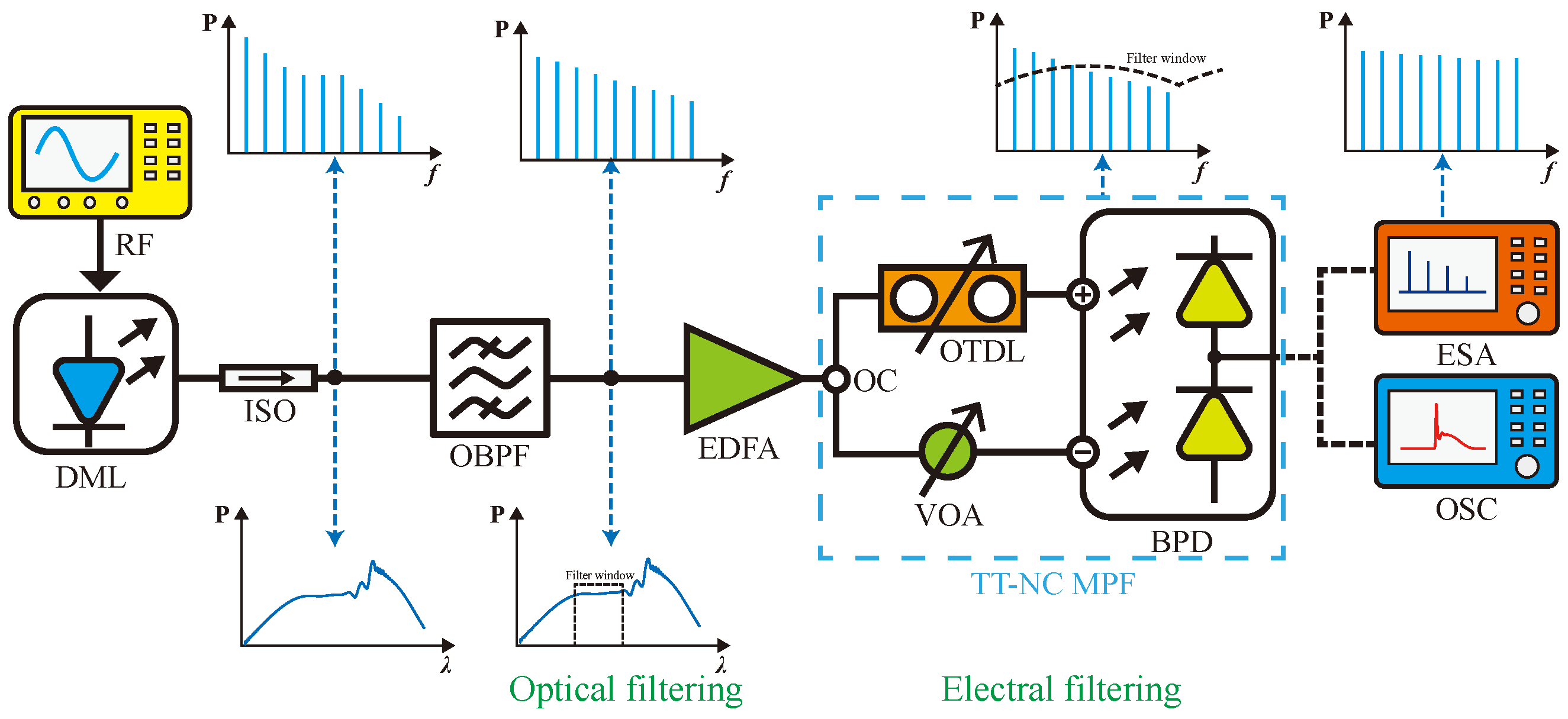
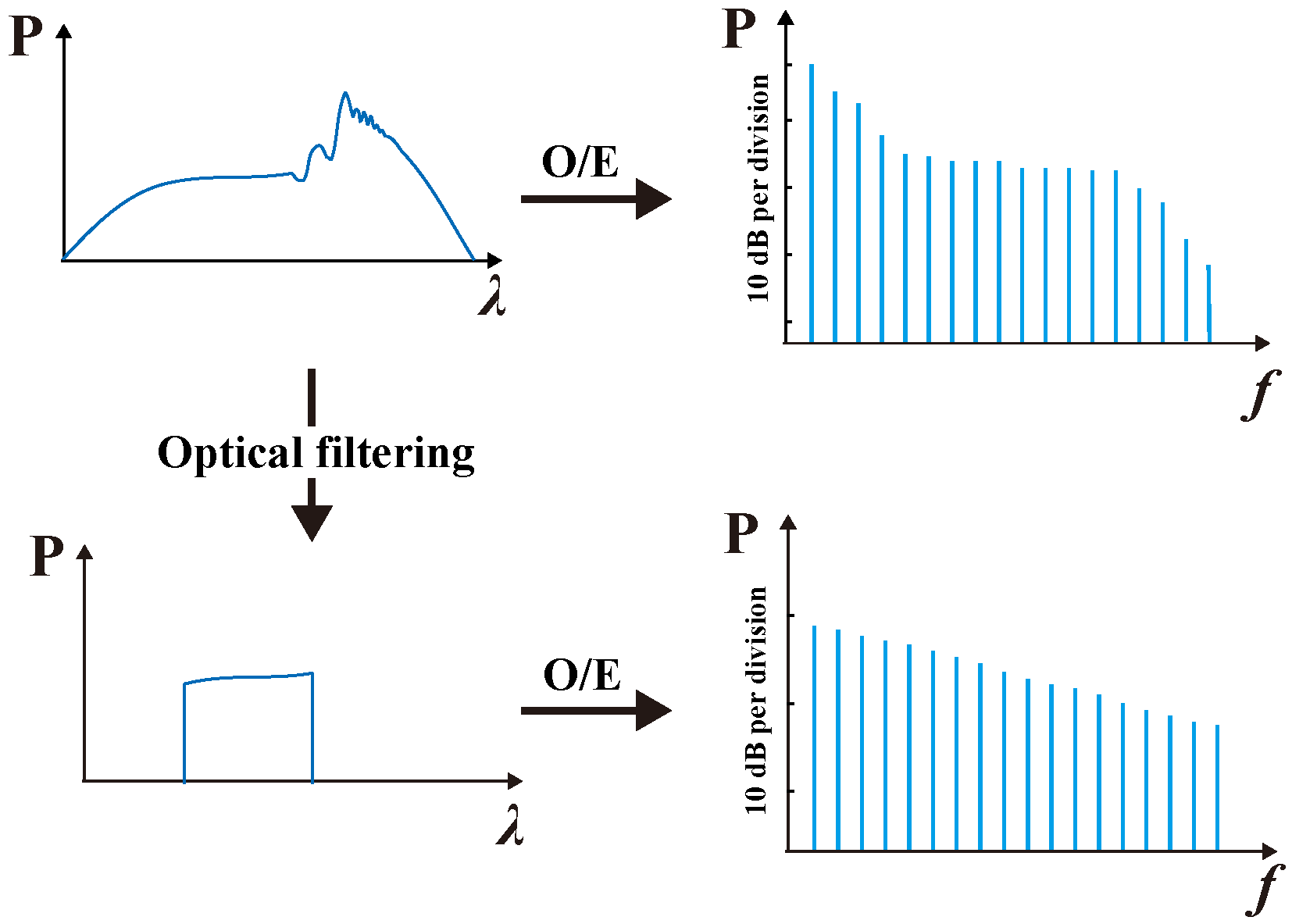
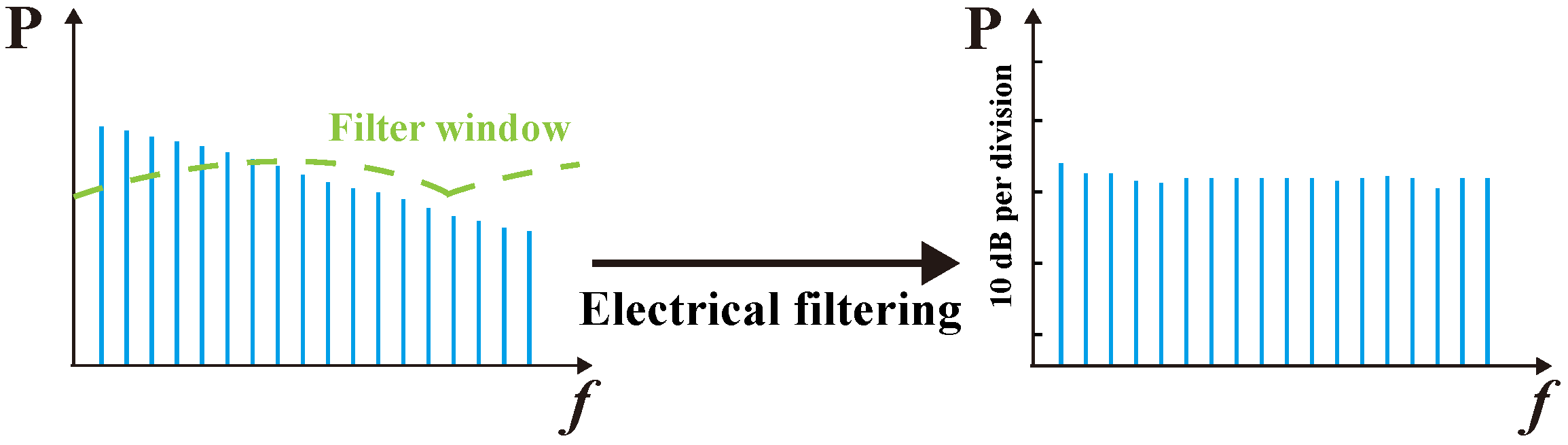
2. Principle
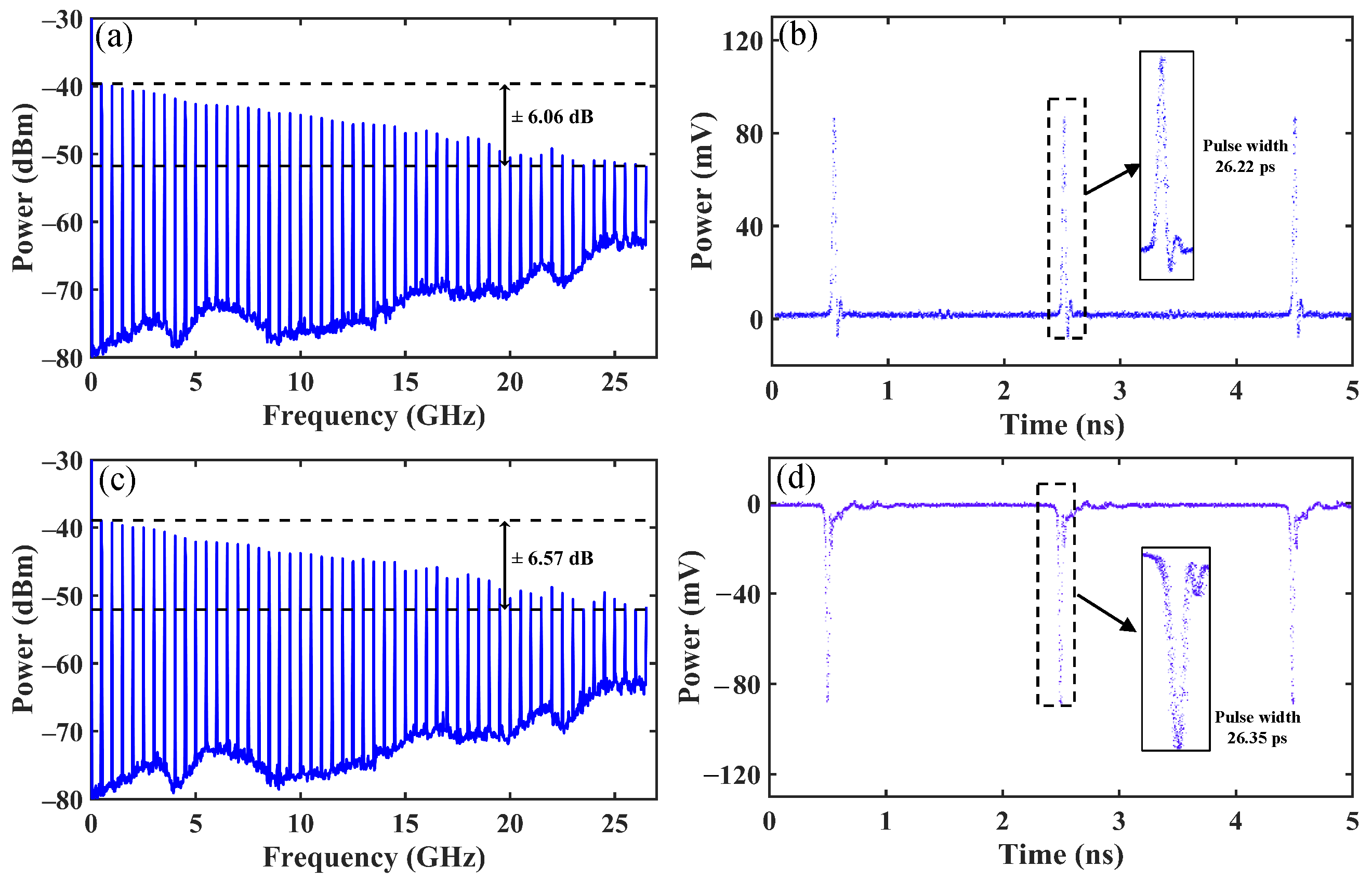
3. Experimental Results and Discussion
4. Conclusions
Author Contributions
Funding
Institutional Review Board Statement
Informed Consent Statement
Data Availability Statement
Conflicts of Interest
References
- Shin, J.; Ryu, Y.; Miri, M.A.; Shim, S.B.; Choi, H.; Alù, A.; Suh, J.; Cha, J. On-Chip Microwave Frequency Combs in a Superconducting Nanoelectromechanical Device. Nano Lett. 2022, 22, 5459–5465. [Google Scholar] [CrossRef] [PubMed]
- Liu, J.; Lucas, E.; Raja, A.S.; He, J.; Riemensberger, J.; Wang, R.N.; Karpov, M.; Guo, H.; Bouchand, R.; Kippenberg, T.J. Photonic microwave generation in the X- and K-band using integrated soliton microcombs. Nat. Photonics 2020, 14, 486–491. [Google Scholar] [CrossRef]
- Zhang, L.H.; Liu, Z.K.; Liu, B.; Zhang, Z.Y.; Guo, G.C.; Ding, D.S.; Shi, B.S. Rydberg Microwave-Frequency-Comb Spectrometer. Phys. Rev. Appl. 2022, 18, 014033. [Google Scholar] [CrossRef]
- Wang, S.P.; Chen, Z.; Li, T. Controllable microwave frequency comb generation in a tunable superconducting coplanar-waveguide resonator*. Chin. Phys. B 2021, 30, 048501. [Google Scholar] [CrossRef]
- Corral, V.; Guzmán, R.; Gordón, C.; Leijtens, X.J.M.; Carpintero, G. Optical frequency comb generator based on a monolithically integrated passive mode-locked ring laser with a Mach–Zehnder interferometer. Opt. Lett. 2016, 41, 1937. [Google Scholar] [CrossRef]
- Wu, H.; Ma, T.; Lu, Q.; Ma, J.; Shi, L.; Mao, Q. Optical frequency combs based on a period-doubling mode-locked Er-doped fiber laser. Opt. Express 2018, 26, 577. [Google Scholar] [CrossRef]
- Akosman, A.E.; Sander, M.Y. Dual comb generation from a mode-locked fiber laser with orthogonally polarized interlaced pulses. Opt. Express 2017, 25, 18592. [Google Scholar] [CrossRef]
- Islam, M.S.; Kovalev, A.V.; Viktorov, E.A.; Citrin, D.S.; Locquet, A. Microwave Frequency Comb Generation by Gain-Switching Versus Relaxation Oscillations. IEEE Photonics Technol. Lett. 2021, 33, 491–494. [Google Scholar] [CrossRef]
- Li, B.; Wu, R.; Wang, Z.; Wang, X.; Zhang, X.; Hong, W.; Liu, H. Rational number harmonic mode-locked dual-loop optoelectronic oscillator with low supermode noise and low intermodulation distortions. Opt. Express 2022, 30, 30303–30311. [Google Scholar] [CrossRef]
- Shen, Z.; Jin, C.; Yang, J.; Zhang, S.; Tang, M.; Wang, K. Method for the generation of microwave frequency combs based on a Vernier optoelectronic feedback loop. Opt. Express 2020, 28, 35118–35127. [Google Scholar] [CrossRef]
- Tang, H.; Kong, Z.; Li, F.; Chen, X.; Li, M.; Zhu, N.; Li, W. Generation of Microwave Frequency Combs Based on Dual-Frequency Injected Optoelectronic Oscillator. J. Light. Technol. 2024, 42, 5522–5528. [Google Scholar] [CrossRef]
- He, Y.; Lopez-Rios, R.; Javid, U.A.; Ling, J.; Li, M.; Xue, S.; Vahala, K.; Lin, Q. High-speed tunable microwave-rate soliton microcomb. Nat. Commun. 2023, 14, 3467. [Google Scholar] [CrossRef] [PubMed]
- Parriaux, A.; Hammani, K.; Millot, G. Electro-optic frequency combs. In Advances in Optics and Photonics; Optica Publishing Group: Washington, DC, USA, 2020; Volume 12, pp. 223–287. [Google Scholar] [CrossRef]
- Rueda, A.; Sedlmeir, F.; Kumari, M.; Leuchs, G.; Schwefel, H.G.L. Resonant electro-optic frequency comb. Nature 2019, 568, 378–381. [Google Scholar] [CrossRef] [PubMed]
- Eliason, T.; Parker, P.A.; Reber, M.A.R. Electro-optic frequency comb generation via cascaded modulators driven at lower frequency harmonics. Opt. Express 2024, 32, 36394–36404. [Google Scholar] [CrossRef]
- Zhang, M.; Buscaino, B.; Wang, C.; Shams-Ansari, A.; Reimer, C.; Zhu, R.; Kahn, J.M.; Lončar, M. Broadband electro-optic frequency comb generation in a lithium niobate microring resonator. Nature 2019, 568, 373–377. [Google Scholar] [CrossRef]
- Zhang, R.; Zhou, P.; Li, K.; Bao, H.; Li, N. Photonic generation of high-performance microwave frequency combs using an optically injected semiconductor laser with dual-loop optoelectronic feedback. Opt. Lett. 2021, 46, 4622–4625. [Google Scholar] [CrossRef]
- Juan, Y.S.; Lin, F.Y. Ultra broadband microwave frequency combs generated by an optical pulse-injected semiconductor laser. Opt. Express 2009, 17, 18596–18605. [Google Scholar] [CrossRef]
- Zhuang, J.P.; Li, X.Z.; Li, S.S.; Chan, S.C. Frequency-modulated microwave generation with feedback stabilization using an optically injected semiconductor laser. Opt. Lett. 2016, 41, 5764–5767. [Google Scholar] [CrossRef]
- Gao, T.; Zhang, Y.; Li, J.; Li, S.; Zhang, Z.; Zhang, S.; Liu, Y. Tunable microwave frequency comb generation via periodic relaxation oscillation in directly modulated laser. Opt. Laser Technol. 2024, 170, 110295. [Google Scholar] [CrossRef]
- Lau, K.Y. Gain switching of semiconductor injection lasers. Appl. Phys. Lett. 1988, 52, 257–259. [Google Scholar] [CrossRef]
- Riecke, S.M.; Wenzel, H.; Schwertfeger, S.; Lauritsen, K.; Paschke, K.; Erdmann, R.; Erbert, G. Picosecond Spectral Dynamics of Gain-Switched DFB Lasers. IEEE J. Quantum Electron. 2011, 47, 715–722. [Google Scholar] [CrossRef]
- Cho, S.-D.; Lee, C.-H.; Shin, S.-Y. Limit of optical pulsewidth in the gain-switched DFB semiconductor laser. IEEE Photonics Technol. Lett. 1999, 11, 782–784. [Google Scholar] [CrossRef]
- Rosado, A.; Pérez-Serrano, A.; Tijero, J.M.G.; Valle, Á.; Pesquera, L.; Esquivias, I. Enhanced optical frequency comb generation by pulsed gain-switching of optically injected semiconductor lasers. Opt. Express 2019, 27, 9155. [Google Scholar] [CrossRef]
- Rosado, A.; Pérez-Serrano, A.; Tijero, J.M.G.; Valle, Á.; Pesquera, L.; Esquivias, I. Experimental study of optical frequency comb generation in gain-switched semiconductor lasers. Opt. Laser Technol. 2018, 108, 542–550. [Google Scholar] [CrossRef]
- Boerma, H.; Ganzer, F.; Runge, P.; Schell, M.; Fernandes, E.; Rudin, B.; Emaury, F. Microwave Photonic PS-Pulse and 140 GHz RF Comb Generator. J. Light. Technol. 2023, 41, 3533–3538. [Google Scholar] [CrossRef]
- Shen, C.; Li, P.; Zhu, X.; Zhang, Y.; Han, Y. Ultra-flat broadband microwave frequency comb generation based on optical frequency comb with a multiple-quantum-well electro-absorption modulator in critical state. Front. Optoelectron. 2019, 12, 382–391. [Google Scholar] [CrossRef]
- He, S.; Deng, Z.; Wang, S.; Xiong, S.; Zhang, M.; Di, Y.; Liu, C.; Li, X.; Luo, D.; Gu, C.; et al. A 62-fs All-Fiber Wideband Flat-Top Spectrum Electro-Optic Comb via Time-Frequency Domain Shaping. J. Light. Technol. 2024, 42, 4756–4762. [Google Scholar] [CrossRef]
- Yuan, J.; Yang, W.; Jing, M.; Zhang, H.; Jiao, Y.; Li, W.; Zhang, L.; Xiao, L.; Jia, S. Quantum sensing of microwave electric fields based on Rydberg atoms. Rep. Prog. Phys. 2023, 86, 106001. [Google Scholar] [CrossRef]


Disclaimer/Publisher’s Note: The statements, opinions and data contained in all publications are solely those of the individual author(s) and contributor(s) and not of MDPI and/or the editor(s). MDPI and/or the editor(s) disclaim responsibility for any injury to people or property resulting from any ideas, methods, instructions or products referred to in the content. |
© 2025 by the authors. Licensee MDPI, Basel, Switzerland. This article is an open access article distributed under the terms and conditions of the Creative Commons Attribution (CC BY) license (https://creativecommons.org/licenses/by/4.0/).
Share and Cite
Long, Q.; Jiang, Y.; Xu, J.; Lan, X.; Feng, J.; Yu, J.; Luo, Y.; Jiang, T.; Zhang, H.; Wu, Y. High-Performance Microwave-Frequency Comb Generation Based on Directly Modulated Laser with Filtering Operations. Photonics 2025, 12, 433. https://doi.org/10.3390/photonics12050433
Long Q, Jiang Y, Xu J, Lan X, Feng J, Yu J, Luo Y, Jiang T, Zhang H, Wu Y. High-Performance Microwave-Frequency Comb Generation Based on Directly Modulated Laser with Filtering Operations. Photonics. 2025; 12(5):433. https://doi.org/10.3390/photonics12050433
Chicago/Turabian StyleLong, Qianyou, Yang Jiang, Jing Xu, Xiaohong Lan, Jinjian Feng, Jiancheng Yu, Yunkun Luo, Tingyi Jiang, Hui Zhang, and Yu Wu. 2025. "High-Performance Microwave-Frequency Comb Generation Based on Directly Modulated Laser with Filtering Operations" Photonics 12, no. 5: 433. https://doi.org/10.3390/photonics12050433
APA StyleLong, Q., Jiang, Y., Xu, J., Lan, X., Feng, J., Yu, J., Luo, Y., Jiang, T., Zhang, H., & Wu, Y. (2025). High-Performance Microwave-Frequency Comb Generation Based on Directly Modulated Laser with Filtering Operations. Photonics, 12(5), 433. https://doi.org/10.3390/photonics12050433