Abstract
Compared with point-to-point underwater wireless optical communication (UWOC) systems with a single direction, the underwater multi-faceted optical base station (OBS) offers independent fields of view and directions for each receiving detector, supporting multiple user access and mobile communication. This study aims at the issue of link interruptions and a limited communication area caused by restricted OBS receiver fields of view when underwater devices move. A field-of-view model and spatial angle diversity reception framework for the multi-faceted OBS in underwater channels have been developed, visualizing the effective reception field of the OBS. This model helps analyze the impact of multi-faceted OBS detector layouts on link performance in underwater environments. Furthermore, under constraints on the number of detectors, configuration adjustments are made to the field-of-view angles and deflection angles of detectors. Simulation results show that, under the same typical underwater environmental conditions, the optimized configuration reduces the blind area compared to the typical configuration, enhancing the effective spatial field of view of the OBS receiver by over 10%. The OBS’s effective communication coverage for mobile devices on different planes is also improved. This research provides a theoretical model and parameter configuration guidelines for the design of the underwater multi-faceted OBS.
1. Introduction
As marine development progresses, the scale of activities such as underwater environmental monitoring, ocean data collection, and tactical reconnaissance continues to grow [1,2]. The demand for real-time high-speed data transmission between underwater devices, such as autonomous underwater vehicles (AUVs), remotely operated vehicles (ROVs), and underwater data nodes, is increasing [3,4]. UWOC with its advantages of high transmission rates, low latency, and low power consumption is considered one of the key technologies for emerging applications such as high-definition video backhaul for unmanned underwater vehicles (UUVs) and real-time interconnection of ocean sensor networks [5,6].
In underwater operational scenarios, establishing an effective UWOC link between mobile devices and data nodes faces numerous challenges [7,8]. The line-of-sight transmission characteristics of optical beam propagation require the transceivers to stay within the effective transmission beam coverage and the receiver’s field of view, which restricts the mobility of devices equipped with optical transceivers [9]. In recent years, the use of wide-beam LEDs to replace narrow-beam laser diodes (LDs) has reduced the tracking and pointing requirements for transceivers [10]. The study in [11] proposed an end-to-end universal UWOC signal model for evaluating the intensity distribution of LED transmission and detector reception. In [12], a transceiver configuration with a single-faceted LED array and a wide-field avalanche photodiode (APD) achieved full-duplex communication. However, despite having used wide-field receivers or increased transmitter beam divergence to relax alignment tolerance, the field-of-view coverage of a single transceiver remains limited, making it difficult to meet mobile devices’ communication requirements.
The underwater multi-faceted OBS, employing angle diversity detectors across multiple receiving planes, has emerged as a promising solution to address the limited field-of-view coverage in mobile communication. This concept was introduced in [13], and the reference [14] investigated the potential of spatial reuse and angular diversity among multi-faceted transceivers. Building on this, Ref. [15] modeled and optimized the spatial beam emission coverage of the underwater multi-faceted OBS, enhancing transmission beam coverage and improved power distribution uniformity. The reference [16] conducted experimental verification of multi-receiver systems underwater with access to multiple sensor nodes. The reference [17] integrated six optical transceivers into an underwater mobile robot and validated the feasibility of omnidirectional underwater communication by deploying wide-field detectors to detect optical signals from varying angles. Additionally, in communication between mobile devices and the underwater OBS, investigating multi-angle signal reception at the OBS to avoid communication interruptions caused by field of view limitations has become a critical issue to address.
In the context of indoor visible light communication (VLC), angle-diversity reception techniques have demonstrated effective capability in managing mobile reception. A seven-faceted angle-diversity receiver architecture was proposed in [18], where independent field-of-view configurations across distinct orientations enabled signal acquisition for mobile users within the coverage zone of indoor systems. The reference [19] introduced a generalized angle-diversity reception structure consisting of a top detector and multiple tilted side detectors to reduce signal-to-noise ratio (SNR) fluctuations in indoor VLC systems. Further research was achieved in [20] by refining the deflection angles of side detectors in angle-diversity reception configurations, which enhanced the uniformity of received optical power distribution in indoor VLC environments. However, when transitioning from indoor to underwater environments, UWOC links exhibit distinct physical characteristics and channel constraints. These are influenced by factors such as seawater attenuation [21], solar background noise [22], and oceanic turbulence [23,24]. Currently, there is limited research on the configuration design and field-of-view coverage performance of the multi-faceted OBS angle-diversity receiver in underwater environments, with a lack analysis on the mobile communication area, which impacts the mobility of devices equipped with optical transceivers.
This paper focuses on the design and performance evaluation of the underwater multi-faceted OBS diversity reception architecture to address the issues mentioned above. We investigate the impact of underwater channels on the performance of multi-faceted OBS receiver links, establish a spatial model for the effective fields of view of the OBS, and analyze the movement area of devices maintaining effective communication links on different elevation planes. Furthermore, by adjusting the field-of-view angles and deflection angles of detectors, we optimize the effective communication area of the OBS reception field of view. Simulation results demonstrate that the optimized receiver configuration expands the spatial reception field and effective communication coverage. The field-of-view modeling provides theoretical foundations for designing an underwater multi-faceted OBS, fostering advancements in UWOC devices’ mobility and the underwater communication network.
This study introduces innovations in the following: (1) the development of the underwater multi-faceted OBS diversity reception architecture model. (2) the configuration adjustment and performance evaluation of the underwater multi-faceted OBS receiver. This includes adjusting OBS receiver parameters based on deployment requirements, assessing the communication range with mobile devices, and enhancing support for device mobility within the coverage area.
The remaining structure of this paper is organized as follows: Section 2 presents main assumptions and the system model for UWOC. Section 3 presents the modeling of multi-angular diversity reception at the OBS. Section 4 evaluates the reception performance of the OBS through numerical results and discussions. Finally, Section 5 concludes with the summary of research and outlines future research directions.
2. Main Assumptions and Channel Model
The application scenario considered as illustrated in Figure 1, where communication occurs between mobile devices transmitter and underwater multi-faceted OBS receiver for data transmission, command, and positioning. The block diagram of the communication link is shown in Figure 2. The transmitter at mobile device adopts LED operating at 532 nm wavelength. This wavelength is chosen due to its relatively low attenuation in seawater [5]. The wide-beam characteristics of LEDs facilitate alignment and pointing with the OBS [24]. At the receiver of the multi-faceted OBS, the OBS structure incorporates multiple detectors, including a top detector and several tilted side detectors. The optical signal processing through a photodetector, transimpedance amplifier (TIA), and low-pass filter (LPF) for noise suppression, followed by selection combining and data demodulation to recover the transmitted information. This work selects APD as the detector for analysis, with its technical maturity and practicality having been validated through numerous UWOC experiments and theoretical studies [11,12,25]. Additionally, this work excludes the effects of vertical stratification effects and focuses on establishing a model that analyzes the relationship between the configuration parameters of multi-faceted OBS receivers (including field-of-view angles and deflection angles) and reception performance (including the reception field of view and effective communication area).
Figure 1.
Application scenario diagram of underwater multi-faceted OBS communication receiver.
Figure 2.
Communication link of the UWOC transmitter to the multi-faceted OBS receiver.
2.1. Signal Transmission
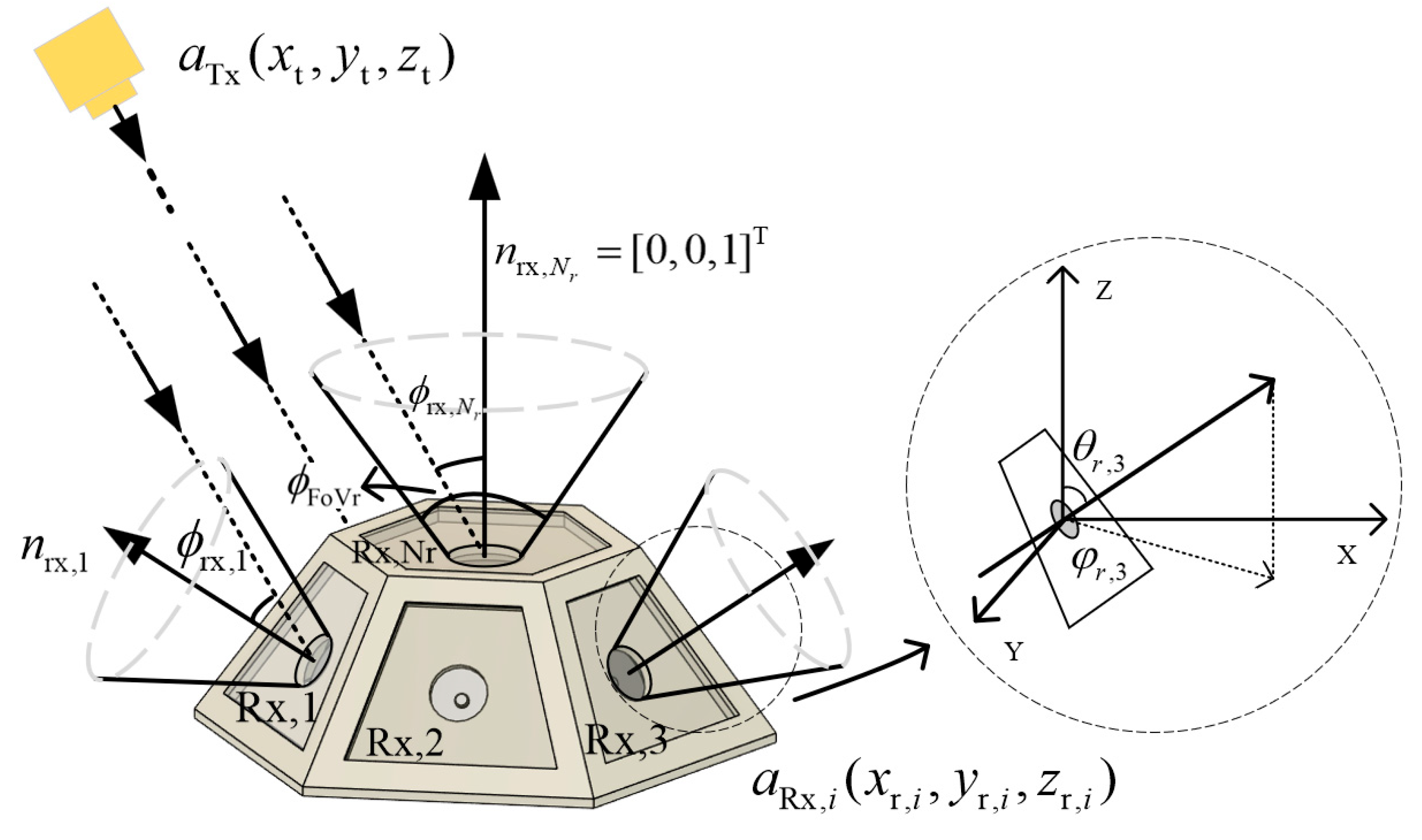
The relationship between the peak radiative intensity and the total radiative power of the transmitting LED light source is defined as follows [11]:
where is the relative intensity function of the light source and represents the angle of angular displacement relative to the optical axis of the light source. The radiative intensity of the emitted light signal is expressed as follows:
Here, is chosen based on the Lambertian light source model to ensure generality [23], with the parameter depending on the light source’s emission half-angle . The expression is as follows:
2.2. Channel Model
The receiving power at each detector of the multi-faceted OBS is as follows:
where the mathematical model for the channel coefficient is
where represents the detector index for each surface of the OBS. The random component represents the influence of underwater turbulence, and represents the combined effects of signal attenuation due to absorption and scattering, the inverse square law of transmission distance, and receiver parameters. Its expression is
where is the attenuation coefficient of light in water, is the transmission distance, and the effective optical collection parameter for the -th receiver is expressed as follows [23]:
At the receiver, is the effective area of the APD, is the transmission coefficient of the optical filter, and is the angle of incidence, which is the angle between the detector’s normal and the incident ray. is the field-of-view angle of the detector, and represents the gain of the non-imaging concentrator, expressed as
where is the refractive index of the non-imaging concentrator.
The impact of oceanic turbulence on UWOC links primarily manifests as random fluctuations in signal strength, which arise from changes in the refractive index of the medium due to variations in water temperature and salinity [5]. Under weak turbulence conditions, this is typically represented by a log-normal distribution. For moderate to strong turbulence, the Gamma–Gamma distribution or exponential distribution can be used to describe the phenomenon [21]. Statistical analysis of ocean observation data has shown that the log-normal probability density function (PDF) has a good match with most measured temperature and salinity gradients [26]. This paper constructs a turbulence characteristic model using the log-normal distribution:
is the turbulence log-amplitude coefficient, which follows a Gaussian distribution. The PDF of the turbulence coefficient is [26]
where and are the mean and variance of the Gaussian distribution’s log-amplitude fading factor, respectively. According to the log-normal distribution’s fading normalization equation, [21]. The relationship between and the scintillation coefficient is as follows:
3. Optical Base Station Diversity Reception
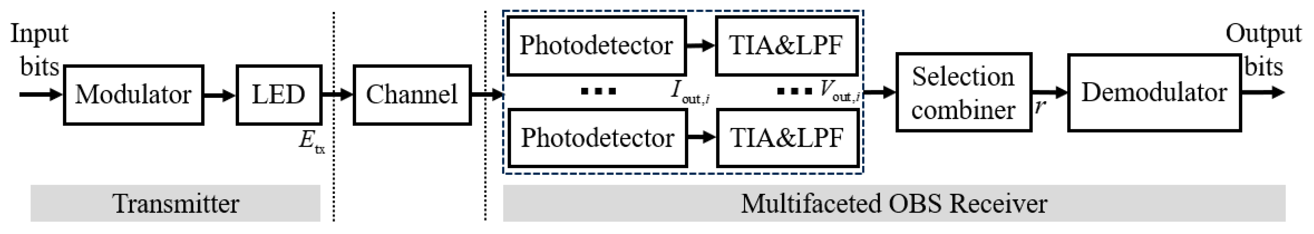
3.1. Detector Output and Data Detection
In the intensity modulation/direct detection mode (IM/DD), for systems using On–Off Keying (OOK) modulation, data transmission is achieved by switching the transmitted optical signal power between the “0” and “1” states. The photocurrent in units of (A) generated by the photodetector is expressed as
where is the APD responsivity, in units of (A/W), is the background noise current, and is the photocurrent noise.
The solar radiation received by the detector introduces background noise optical power, and the resulting photocurrent can be expressed as [23]
where is the bandwidth of the optical filter, represents the downward spectral irradiance at sea level, and is the underwater depth at the OBS receiver.
The signal in units of (V) at the output of the faceted detector, after passing through the LPF, is expressed as
where is the load resistance of the TIA, and is the thermal noise component of the . The total noise variance corresponding to the output signal, in units of (V2), is given by
where is the variance of the signal shot noise, is the variance of the background noise, and is the variance of the thermal noise. The expression is as follows:
Here, , , , , and represent the electron charge, Boltzmann constant, Kelvin temperature, low-pass filter bandwidth, and internal amplification gain of the APD, respectively. is the APD excess noise factor, expressed as
where is the ionization ratio.
In the multi-faceted detector angle diversity architecture of this model, the spatial coverage area of each faceted receiver is independent. The detection channels with the highest incident optical power are activated based on real-time signal strength indications, while the remaining detector channels are kept silent. This strategy effectively eliminates the noise accumulation problem introduced by misaligned detector, while maintaining spatial diversity gain [18]. It is assumed that the combiner switches detectors instantaneously, neglecting the effect of switching time. The representation of this selective combining strategy can be modeled as
The instantaneous bit error rate can be expressed as [26,27]
where and represent the signal components for the signals 0 and 1 of input demodulator, and represent the noise variance for the signals 0 and 1 of input demodulator, and is the OOK demodulation threshold. Considering the effects of turbulence, the average bit error rate is calculated as
3.2. Multi-Faceted OBS Angle Diversity Receiver
The multi-faceted OBS receiver structure consists of detectors, including a top-faceted detector and side-faceted detectors, as shown in Figure 3. The side-faceted detectors are numbered sequentially as , and the top-faceted detector is numbered . Each detector has the same field-of-view angle and optical performance parameters. The side-faceted detectors are evenly distributed in a circular pattern and are rotated by an angle of deflection. The deflection angle is the angle between the receiving normal of the side-faceted detector and the receiving normal of the top-faceted detector.
Figure 3.
Geometric diagram of the transmitter to a multi-faceted OBS receiver UWOC link.
Let the Cartesian coordinates of the transmitter device be and the coordinates of the detector on the OBS be . In this model, it is assumed that the transmitter is aligned to OBS, neglecting pointing errors of the optical transmitter. The primary focus is on the impact of the configuration of the multi-faceted OBS receiver parameters on performance. The OBS receiver is assumed to be placed in the vertical direction, with the top-faceted detector’s deflection angle being 0°, meaning that the unit vector of the optical base station’s top-faceted detector is , and all side-faceted detectors have the same deflection angle. The deflection angle of the detector can be expressed as
represents the azimuth angle of the side-faceted detector’s direction vector projected onto the X-Y plane. Assuming the azimuth angle of the first side-faceted detector is fixed at , the azimuth angle of the side-faceted detector can be expressed as
This leads to the direction vector of the side-faceted detectors after deflection, , given by
Thus, the angle between the incident line from the transmitter and the direction vector of each detector can be expressed as
4. Numerical Results and Discussions
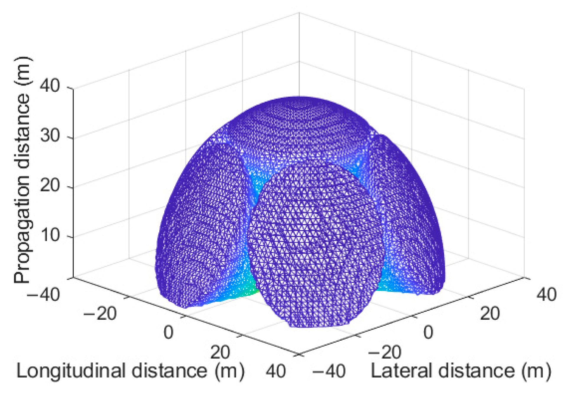
4.1. Multi-Faceted OBS Modeling
Due to the lack of current research on the architecture design of multi-faceted OBS angle diversity reception and performance evaluation of reception-field coverage in underwater environments, this chapter models the communication link process in Figure 2 and the multi-faceted OBS spatial reception architecture in Figure 3. The spatial reception field of a six-faceted OBS and the mobility of devices communicating with it are simulated. The typical configuration generally uses a detector field-of-view angle of 60° and a deflection angle of 60°. This configuration achieves a uniform circular field-of-view layout, which is a commonly used typical parameter value in related experiments and theoretical research [18]. Table 1 lists the multi-faceted OBS model parameters and underwater channel parameter settings, following the parameter definitions in Section 2. The values of these parameters fall within reasonable ranges [23,28,29], ensuring their applicability to UWOC systems.
Table 1.
Multi-faceted OBS model and underwater channel parameter settings.
Figure 4 shows the receiving field of view of the six-faceted OBS, the optical power sensitivity threshold of the OBS receiver is set to −41 dBm, and the OBS receiver configuration is , . The three-dimensional field of view is presented through longitudinal and lateral reception. It can be seen that the multi-faceted receiver detector exhibits a conical reception mode, enabling multi-angle detection. In the communication area analysis, Figure 5 shows the effective communication area on the plane 15 m and 25 m vertically above the six-faceted OBS, demonstrating communication performance under different bit error rate thresholds from BER = 10−2 to 10−5. The effective communication area increases significantly and can meet the communication needs of mobile devices by using multi-faceted detectors. However, with the configuration of and , there is still a coverage gap blind zone between the fields of view of the detectors.
Figure 4.
Spatial effective receiving field of view of the six-faceted OBS, , .
Figure 5.
Effective communication area of a mobile device above the six-faceted OBS at different distances from the horizontal plane, , . (a) At a height of 15 m; (b) At a height of 25 m.
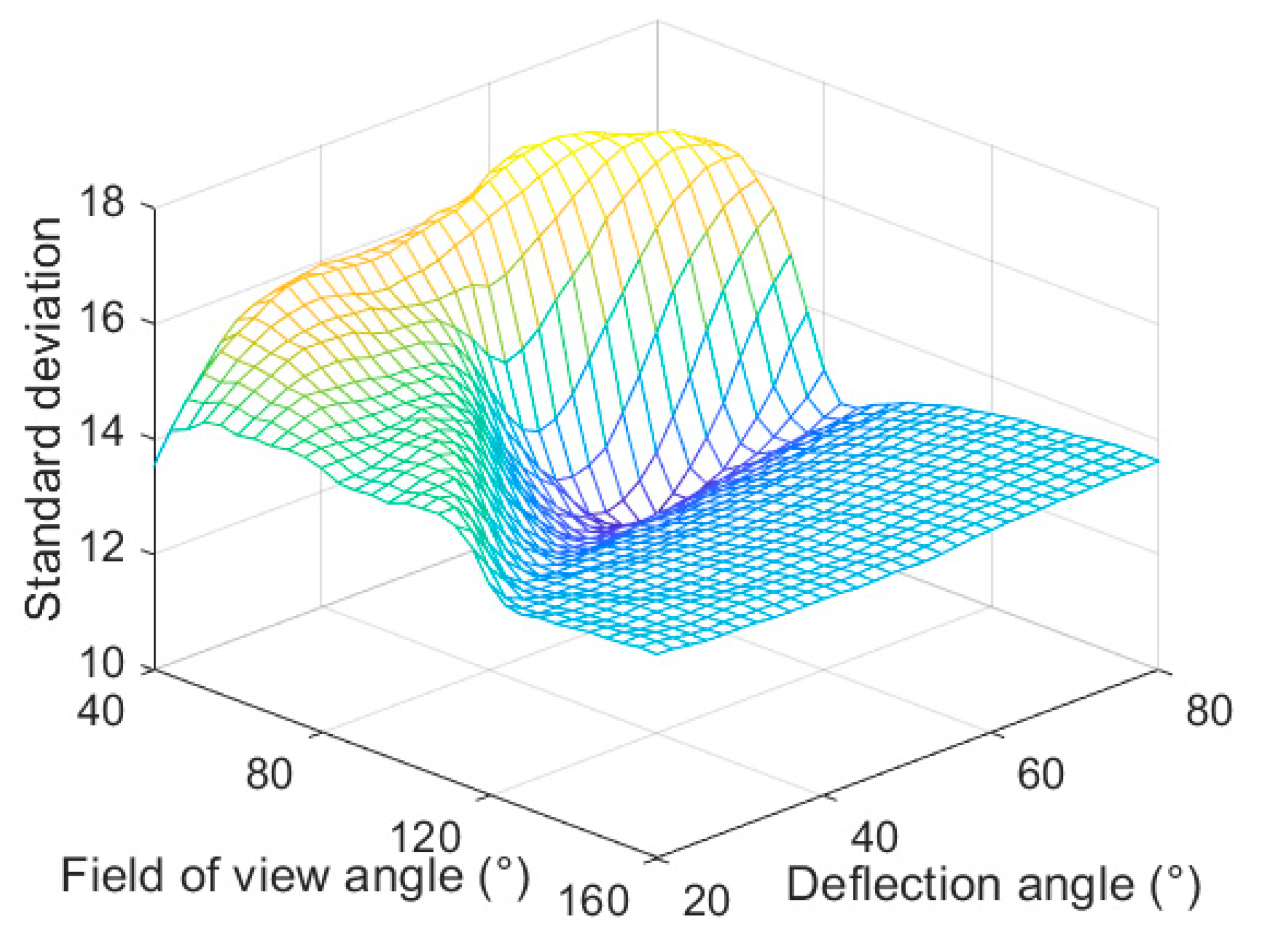
4.2. Multi-Faceted OBS Receiving Configuration Parameter Optimization
In the typical configuration, the field-of-view blind zone at the junction between the top and the sides detectors cause communication interruptions when underwater devices move. To further optimize the receiver link performance, we analyzed the optimization of the receiving field-of-view angle and the deflection angle to reduce the blind zone and enhance the uniformity of the received optical power.
Based on the configuration in Table 1 and the simulation results in Figure 4 and Figure 5, we evaluated the effect of different positions on the received optical power at the OBS at height levels (5 m, 15 m, and 25 m) above the OBS, each with a range of 50 m × 50 m. We applied the minimum standard deviation criterion on the divided three-level transmission distance planes to quantify the uniformity of the received optical power distribution, thus assessing the effect of different configurations on blind zone suppression. Figure 6 shows the impact of different parameter combinations on the standard deviation of the optical power distribution. The simulation results indicate that when the field-of-view angle is set to 72° and the deflection angle is set to 62°, this parameter combination achieves optimal received power distribution uniformity in this scenario. Then, based on the optimized configuration, we further evaluated the communication performance of the OBS, including its bit error rate, spatial reception field, and effective communication coverage.
Figure 6.
Standard deviation distribution of the uniformity of optical power distribution in the six-faceted OBS under different field-of-view and deflection angle configurations.
Figure 7 shows the spatial effective receiving field of view after the optimized parameter configuration. By adjusting the field-of-view and deflection angle, the blind zone distribution between adjacent OBS detector surfaces has been improved. The effective communication range is shown in Figure 8, where the blind zones within the field of view of adjacent OBS detectors at 15 m vertically and 25 m horizontally above the OBS are eliminated, reducing the communication interruptions caused by blind zones during the movement of underwater devices.
Figure 7.
Spatial effective receiving field of view of the six-faceted OBS, , .
Figure 8.
Effective communication area of a mobile device above the six-faceted OBS at different distances from the horizontal plane, , . (a) At a height of 15 m; (b) At a height of 25 m.
Figure 9 shows the SNR distribution at different angles when the OBS is located at the origin of the coordinate system and the distance between the mobile device and the OBS is 35 m, under both typical and optimized configurations. In Figure 9a,c, the mobile device moves along a semi-circular trajectory around the Y-axis, starting from 0° (positive X-axis), rotating to 90° (positive Z-axis), and then to 180° (negative X-axis). In Figure 9b,d, the mobile device follows a semi-circular trajectory around the X-axis, starting from 0° (positive Y-axis), rotating to 90° (positive Z-axis), and then to 180° (negative Y-axis). It can be observed that the optimized configuration significantly reduces the field-of-view blind zone compared to the typical configuration and effectively mitigates the SNR degradation caused by gaps between detectors at different angles.
Figure 9.
SNR distribution at different angles for two configurations. (a) Typical configuration, mobile device rotating along a semi-circular trajectory around the Y-axis; (b) Typical configuration, mobile device around the X-axis; (c) Optimized configuration, mobile device around the Y-axis; (d) Optimized configuration, mobile device around the X-axis.
Figure 10 shows the bit error rate at different distances and angles around the Y-axis for the mobile device and OBS under both typical and optimized configurations. It can be observed that as the communication distance increases, the bit error rate gradually rises. At 90° and 135° around the Y-axis of the OBS, the transmission distance for the optimized configuration is slightly reduced by about 4% compared to the typical configuration at the same bit error rate threshold. This effect is primarily due to the gain effect introduced by the small field-of-view angle (according to Equation (8)). However, at 45° around the Y-axis of the OBS, communication is interrupted in the typical configuration due to the blind zone, while the optimized configuration maintains a link connection.
Figure 10.
Bit error rate of the mobile device and OBS at different distances and angles around the Y-axis for two configurations.
The comparison of the three-dimensional spatial field-of-view coverage parameters is shown in Figure 11. In a three-dimensional space of 60 m in length × 60 m in width × 25 m in height, the optimized configuration increased the effective field-of-view coverage from 72.05% to 82.22%, a 10.17% improvement. In a three-dimensional space of 60 m × 60 m × 30 m, the coverage increased from 66.75% to 77.34%, a 10.59% improvement. The optimized configuration significantly enhanced the spatial coverage capability of the OBS.
Figure 11.
Effective field-of-view coverage percentage in three-dimensional space for different configurations of the OBS.
The comparison of effective communication ranges in the planar is shown in Figure 12. On a plane (50 m × 50 m) at a distance of 5 m above the OBS, the effective range for a BER ≤ 10⁻3 improved from 81.26% before optimization to 95.49%, with a particularly notable performance improvement in low-height planes. At a height of 15 m, the coverage increased from 95.28% to 99.71%. This result indicates that the six-faceted receiver in this configuration has nearly reached its performance limit. At a height of 25 m, the coverage improved from 81.41% to 88.79%, showing some enhancement. As the plane height increases, the optical power gradually weakens, resulting in a slight decrease in coverage. Overall, by adjusting the parameter configuration, the effective communication range has been significantly improved.
Figure 12.
Effective communication area coverage percentage of a mobile device at various vertical distances from the OBS on a horizontal plane (50 m × 50 m).
5. Conclusions
This study proposes a spatial angle diversity reception modeling framework for an underwater multi-faceted OBS, focusing on the problem of link interruptions and limited communication area caused by the restricted fields of view of the OBS when underwater device moves. This research concentrates on the architecture design and performance evaluation of diversity reception in the underwater multi-faceted OBS. By establishing a model of the multi-faceted receiver field of view in underwater channels, this study helps visually observe and adjust the effective communication area for mobile devices. Furthermore, in the same scenario, we adjusted the parameters of the field-of-view angles and deflection angles to improve the effective spatial coverage volume of the reception communication link and enhance the coverage of the effective device communication area during movement. These research findings offer theoretical support and configuration references for the design of an underwater OBS, meeting the communication needs of underwater mobile devices in fields such as unmanned device control and deep-sea exploration.
Additionally, this study primarily establishes a model relating the configuration parameters of underwater multi-faceted receivers to their reception performance (bit error rate, reception field of view, and effective communication range). Future research could further extend this framework by exploring adaptive designs under vertical stratification conditions, analyzing the performance differences of various combination technologies in underwater multi-faceted OBS reception, and considering the impact of water scattering on the transmitted light field and receiver field of view. This would enhance the applicability and scope of this study.
Author Contributions
Conceptualization, J.S. and J.A.; methodology, J.S.; software, J.S.; validation, J.S.; formal analysis, C.M. and X.T.; investigation, H.G.; resources, J.A.; data curation, C.M. and X.T.; writing—original draft preparation, J.S.; writing—review and editing, H.G. and X.T.; visualization, J.S.; supervision, J.A.; project administration, J.A.; funding acquisition, J.A. All authors have read and agreed to the published version of the manuscript.
Funding
This research was funded by the Innovation Project of GUET Graduate Education, grant number 2022YCXB04.
Institutional Review Board Statement
Not applicable.
Informed Consent Statement
Not applicable.
Data Availability Statement
The original contributions presented in this study are included in this article; further inquiries can be directed to the corresponding author.
Conflicts of Interest
The authors declare no conflicts of interest.
References
- González-García, J.; Gómez-Espinosa, A.; Cuan-Urquizo, E.; García-Valdovinos, L.G.; Salgado-Jiménez, T.; Escobedo Cabello, J.A. Autonomous underwater vehicles: Localization, navigation, and communication for collaborative missions. Appl. Sci. 2020, 10, 1256. [Google Scholar] [CrossRef]
- Schill, F.; Bahr, A.; Martinoli, A. Vertex: A new distributed underwater robotic platform for environmental monitoring. In Distributed Autonomous Robotic Systems: The 13th International Symposium; Springer: Cham, Switzerland, 2018; pp. 679–693. [Google Scholar] [CrossRef]
- Hoeher, P.A.; Sticklus, J.; Harlakin, A. Underwater optical wireless communications in swarm robotics: A tutorial. IEEE Commun. Surv. Tutor. 2021, 23, 2630–2659. [Google Scholar] [CrossRef]
- Connor, J.; Champion, B.; Joordens, M.A. Current algorithms, communication methods and designs for underwater swarm robotics: A review. IEEE Sens. J. 2020, 21, 153–169. [Google Scholar] [CrossRef]
- Kaushal, H.; Kaddoum, G. Underwater optical wireless communication. IEEE Access 2016, 4, 1518–1547. [Google Scholar] [CrossRef]
- Saeed, N.; Celik, A.; Al-Naffouri, T.Y.; Alouini, M.-S. Underwater optical wireless communications, networking, and localization: A survey. Ad Hoc Netw. 2019, 94, 101935. [Google Scholar] [CrossRef]
- Sabril, S.; Jasman, F.; Hassan, W.H.W.; Mutalip, Z.A.; Mohd-Mokhtar, R.; Hassan, Z. The Effect of Medium Inhomogeneity in Modeling Underwater Optical Wireless Communication. J. Commun. 2021, 16, 386–393. [Google Scholar] [CrossRef]
- Lv, Z.; He, G.; Qiu, C.; Liu, Z. Investigation of underwater wireless optical communications links with surface currents and tides for oceanic signal transmission. IEEE Photonics J. 2021, 13, 1–8. [Google Scholar] [CrossRef]
- Nasser, A.G.; Ali, M.A.A. Performance of LED for line-of-sight (LoS) underwater wireless optical communication system. J. Opt. Commun. 2024, 44, s1355–s1363. [Google Scholar] [CrossRef]
- Jasman, F.; Green, R.J.; Leeson, M.S. Impact of receiver field of view on underwater optical wireless communications. Microw. Opt. Technol. Lett. 2017, 59, 837–840. [Google Scholar] [CrossRef]
- Doniec, M.; Angermann, M.; Rus, D. An end-to-end signal strength model for underwater optical communications. IEEE J. Ocean. Eng. 2013, 38, 743–757. [Google Scholar] [CrossRef]
- Li, J.; Yang, B.; Ye, D.; Wang, L.; Fu, K.; Piao, J.; Wang, Y. A real-time, full-duplex system for underwater wireless optical communication: Hardware structure and optical link model. IEEE Access 2020, 8, 109372–109387. [Google Scholar] [CrossRef]
- Baiden, G.; Bissiri, Y.; Masoti, A. Paving the way for a future underwater omni-directional wireless optical communication systems. Ocean Eng. 2009, 36, 633–640. [Google Scholar] [CrossRef]
- Barroso, A.R.F.; Baiden, G.; Johnson, J. Teleoperation of mining equipment using optical wireless communications. In Proceedings of the 2015 Seventh International Conference on Ubiquitous and Future Networks, Sapporo, Japan, 7–10 July 2015; pp. 727–733. [Google Scholar] [CrossRef]
- Shi, J.; Ma, C.; Tian, X.; Guo, H.; Ao, J. Optimization and Modeling of Optical Emission Spatial Coverage from Underwater Multi-Faceted Optical Base Stations. Photonics 2024, 12, 4. [Google Scholar] [CrossRef]
- Kong, M.; Guo, Y.; Sait, M.; Alkhazragi, O.; Kang, C.H.; Ng, T.K.; Ooi, B.S. Toward automatic subsea operations using real-time underwater optical wireless sensor networks. IEEE Photonics J. 2021, 14, 1–8. [Google Scholar] [CrossRef]
- Zhang, H.; Gao, Y.; Tong, Z.; Yang, X.; Zhang, Y.; Zhang, C.; Xu, J. Omnidirectional optical communication system designed for underwater swarm robotics. Opt. Express 2023, 31, 18630–18644. [Google Scholar] [CrossRef]
- Burton, A.; Ghassemlooy, Z.; Rajbhandari, S.; Liaw, S.K. Design and analysis of an angular-segmented full-mobility visible light communications receiver. Trans. Emerg. Telecommun. Technol. 2014, 25, 591–599. [Google Scholar] [CrossRef]
- Chen, C.; Zhong, W.-D.; Yang, H.; Zhang, S.; Du, P. Reduction of SINR fluctuation in indoor multi-cell VLC systems using optimized angle diversity receiver. J. Light. Technol. 2018, 36, 3603–3610. [Google Scholar] [CrossRef]
- Chi, S.; Wang, P.; Niu, S.; Che, H.; Wang, Z.; Wu, Y. Uniformity improvement on received optical power for an indoor visible light communication system with an angle diversity receiver. Appl. Opt. 2021, 60, 8031–8037. [Google Scholar] [CrossRef]
- Jamali, M.V.; Mirani, A.; Parsay, A.; Abolhassani, B.; Nabavi, P.; Chizari, A.; Khorramshahi, P.; Abdollahramezani, S.; Salehi, J.A. Statistical studies of fading in underwater wireless optical channels in the presence of air bubble, temperature, and salinity random variations. IEEE Trans. Commun. 2018, 66, 4706–4723. [Google Scholar] [CrossRef]
- Ata, Y.; Kiasaleh, K. Analysis of optical wireless communication links in turbulent underwater channels with wide range of water parameters. IEEE Trans. Veh. Technol. 2023, 72, 6363–6374. [Google Scholar] [CrossRef]
- Hamza, T.; Khalighi, M.-A.; Bourennane, S.; Léon, P.; Opderbecke, J. Investigation of solar noise impact on the performance of underwater wireless optical communication links. Opt. Express 2016, 24, 25832–25845. [Google Scholar] [CrossRef] [PubMed]
- Khalil, R.A.; Babar, M.I.; Saeed, N.; Jan, T.; Cho, H.-S. Effect of link misalignment in the optical-internet of underwater things. Electronics 2020, 9, 646. [Google Scholar] [CrossRef]
- Ju, M.; Shi, H.; Li, Y.; Huang, P.; Tan, G. Effect of the APD Receiver’s Tilted Angle on Channel Capacity for Underwater Wireless Optical Communications. Electronics 2021, 10, 2246. [Google Scholar] [CrossRef]
- Ijeh, I.C.; Khalighi, M.A.; Elamassie, M.; Hranilovic, S.; Uysal, M. Outage probability analysis of a vertical underwater wireless optical link subject to oceanic turbulence and pointing errors. J. Opt. Commun. Netw. 2022, 14, 439–453. [Google Scholar] [CrossRef]
- Dabiri, M.T.; Sadough, S.M.S.; Khalighi, M.A. FSO channel estimation for OOK modulation with APD receiver over atmospheric turbulence and pointing errors. Opt. Commun. 2017, 402, 577–584. [Google Scholar] [CrossRef]
- Luo, H.; Wang, X.; Bu, F.; Yang, Y.; Ruby, R.; Wu, K. Underwater real-time video transmission via wireless optical channels with swarms of AUVs. IEEE Trans. Veh. Technol. 2023, 72, 14688–14703. [Google Scholar] [CrossRef]
- Zaye, M.M.; Shokair, M.; Elagooz, S.; Elshenawy, H. Feasibility analysis of line of sight (LOS) underwater wireless optical communications (UWOCs) via link budget. Opt. Quantum Electron. 2024, 56, 1012. [Google Scholar] [CrossRef]
Disclaimer/Publisher’s Note: The statements, opinions and data contained in all publications are solely those of the individual author(s) and contributor(s) and not of MDPI and/or the editor(s). MDPI and/or the editor(s) disclaim responsibility for any injury to people or property resulting from any ideas, methods, instructions or products referred to in the content. |
© 2025 by the authors. Licensee MDPI, Basel, Switzerland. This article is an open access article distributed under the terms and conditions of the Creative Commons Attribution (CC BY) license (https://creativecommons.org/licenses/by/4.0/).