1. Introduction
Due to the direct requirements of AI, 5G/B5G/6G mobile access, quantum computing, big data, high speed internet, 8K video games and services, video conferencing, and last-mile data access for all consumers, wavelength-division multiplexing passive optical network (WDM-PON) technologies are potential candidates that should be investigated in order to meet the needs of broadband users [
1,
2,
3,
4]. WDM-PON access with 2.5 to 100 Gbit/s has the advantages of high flexibility, wide capacity, and cost-effectiveness for end users [
5]. Also, to increase data rates for customers, the use of hybrid polarization–division multiplexing (PDM), WDM, and coherent optical technologies in PON access to provide point-to-point (PtP) traffic data has also been explored [
6,
7]. The PDM technique doubles the data rate of each WDM wavelength through an orthogonal dual-polarized signal [
8,
9]. However, under such high-speed and high-capacity WDM signal transmission, the occurrence of fiber breakage can cause great inconvenience for end users. Hence, the reliability and stability of data transmission in PON networks are especially important. Meanwhile, fiber fault management is a necessary issue in network management to improve networks’ survivability and reliability. Protection against and prevention of breakpoints on the feeder fiber and distribution fiber should be important topics of study to support ongoing PON development [
10,
11,
12,
13].
To achieve more flexible and reliable signal access in PONs, free-space optical (FSO) communication technologies have been adopted, albeit with certain topographical limitations [
14]. When fiber optic links are not feasible, FSO techniques can be utilized to address this challenge through wireless optical links [
15]. Additionally, WDM FSO signals can be integrated into PON systems to support both baseband and FSO traffic simultaneously. Consequently, a hybrid fiber–FSO PON can enable intelligent signal routing, adaptable bandwidth, diverse network topologies, and cost-effective deployment, enhancing overall access efficiency [
16,
17,
18].
As mentioned above, to avoid the occurrence of fiber faults, the integration and application of protected fiber and FSO transmission links is an important research topic in the development of self-restored PON [
16]. In 2003, Chan et al. proposed 1:1 protection capability in both downstream and upstream fiber connections via an adjacent optical network unit (ONU) through protected fiber, based on earlier research in tree-based networks [
19]. In 2009, Sue et al. proposed an access network scheme to offer full protection capability for WDM-PON systems, which also featured lower rates of unavailability, lower construction costs, and a reduced wavelength requirement [
20]. In 2016, Zhang et al. designed a ring-based long-reach PON architecture with complex integration of optical switches (OSWs) to protect against faults [
21]. Moreover, combined fiber–FSO transmission paths to avoid fiber breaks have also been proposed for use in tree- and ring-based PONs to enhance network survivability and reliability [
10,
16,
22,
23].
In this paper, we describe a WDM-PON system that self-protects against fiber breakpoints through additional protected fiber or FSO link paths. To achieve operational fault protection, the main network units of the RN and ONU in the PON system were redesigned. Thus, normal connected fiber and protected optical fiber (or the FSO path) can be used to connect the OLT to the RN and the RN to the ONU modules, respectively, to achieve self-protection. To avoid fiber breakage on the feeder or distribution fiber in this WDM-PON system, the presented WDM network can accomplish operational self-restoration supported by self-detection. To demonstrate the signal performance of the WDM upstream and downstream wavelengths, eight optical channels ranging from 1530.33 to 1538.82 nm with an interval of 0.8 nm were employed for testing, both when the protected fiber and FSO link paths were used and when they were not. The experiments to measure the bit error rate (BER) were conducted using 25 Gbit/s on-off keying (OOK) modulation on each WDM channel through 25 km single-mode fiber (SMF) and 25 km SMF + 2 m FSO connections, respectively. Based on the measured BER results, the corresponding power budgets of the selected WDM signals were met and were smaller than the total insertion loss of the proposed PON structure. Moreover, to deliver longer FSO transmission length between adjacent ONUs, an optical amplifier could be applied in each ONU to enhance the FSO power. Compared with previous studies [
13,
16,
22,
23], the presented WDM access network features a simpler operational mechanism and enhanced network scalability. As a result, the proposed WDM-PON system, based on fiber and FSO-based ONUs, can not only avoid fiber faults but also enhance network reliability and flexibility for data connections.
2. Proposed PON Architecture
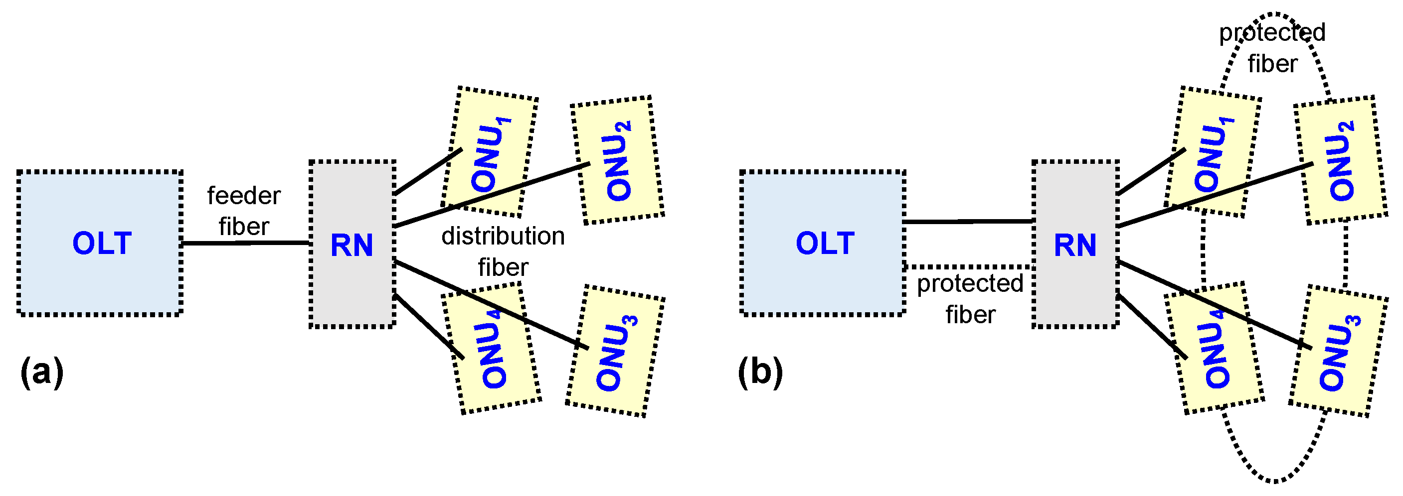
Commonly, the feeder fiber between the OLT and RN and the distribution fibers between the RN and ONUs may be interrupted due to fiber breakpoints in the conventional WDM-PON architecture, as shown in
Figure 1a. Fiber breakpoints in such PON networks may be caused by careless construction or natural disasters. To avoid and solve breakpoints on the feeder and distribution fibers, we demonstrate a new WDM-PON network with alternative link paths through protected fiber and FSO connection paths simultaneously for fault protection. Hence, a dual feeder fiber is applied between the OLT and RN, and using a fiber ring path to connect each ONU in series can produce the protected fiber for restoring WDM signal access, as seen in
Figure 1b, when a fault occurs on the feeder or distribution fibers. The protected fiber is drawn as a dotted line in
Figure 1b. Therefore, the corresponding OLT, RN, and ONU modules need to be redesigned for selecting the alternative fiber path (protected fiber) for routing the link path to avoid fiber faults. The proposed PON architecture is regarded as a star-ring type WDM access network, as observed in
Figure 1b.
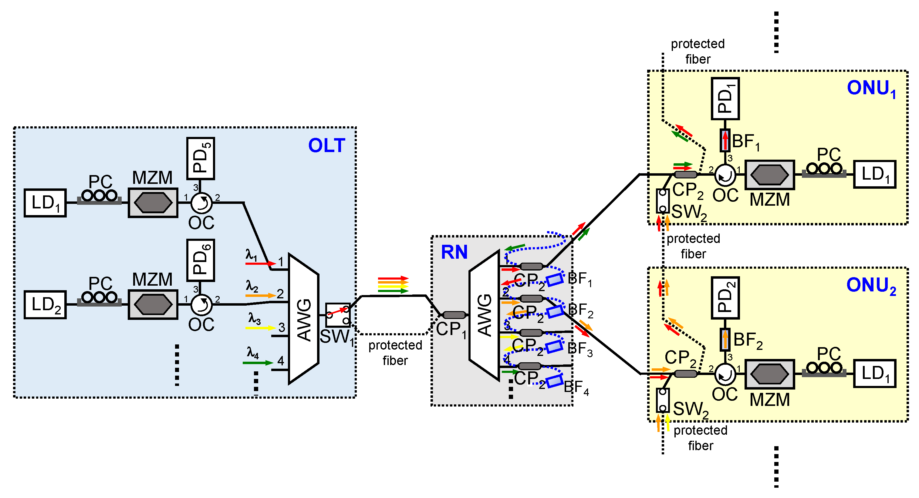
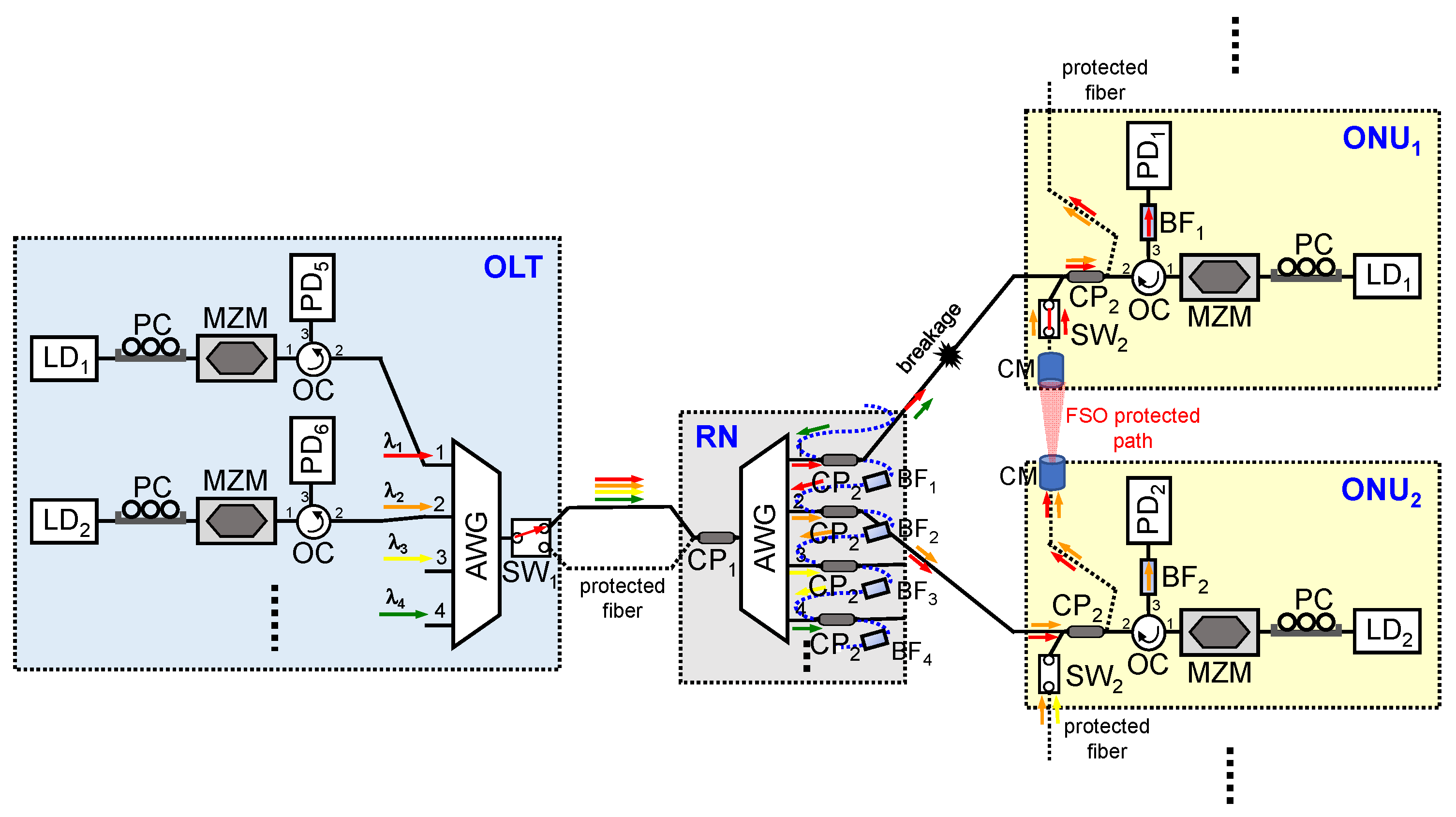
Then, a new self-healing WDM-PON system with star-ring access architecture is demonstrated, as drawn in
Figure 2. To achieve the fault protection function through the protected fiber path, the new OLT, RN, and ONU modules are redesigned. In the OLT, each WDM laser diode (LD) connects to a polarization controller (PC), 40 GHz Mach–Zehnder modulator (MZM), optical circulator (OC), 1 ×
N WDM multiplexer (MUX), and 1 × 2 optical switch (SW
1) for downstream traffic, respectively. The two connection ports of SW
1 are linked to the feeder and protected fibers as normal and protected fiber paths, respectively. In addition, the OLT also involves a 40 GHz PIN photodiode (PD) to receive the upstream WDM signal from the corresponding ONU. In the remote node (RN) site, it consists of a 1 × 2 and 50:50 optical coupler (CP
1), a 1 ×
N WDM demultiplexer (DEMUX),
N 2 × 2, and 50:50 optical couplers (CP
2) and
N bandpass filters (BF
1 to BF
N) with different passbands to filter and permit the matching WDM wavelength. Next, each optical network unit (ONU) module is constructed with a 1 × 1 optical switch (SW
2)
, an OC, a CP
2, a corresponding BF
N, a corresponding upstream LD, a PC, 40 GHz PIN PD, and a 40 GHz MZM, respectively. As a result, based on the designed OLT, RN, and ONU modules, the new star-ring type WDM-PON access can provide the fiber breakpoint protection between feeder and distribution fibers through the routing link path of protected fiber, as exhibited in
Figure 2.
As displayed in
Figure 2, the dotted lines are used to represent the protected fibers between OLT and RN and between adjacent ONUs. Under normal signal access, all the WDM downstream wavelengths (λ
1 to λ
N) at the OLT will transmit to the RN and enter each corresponding ONU, when the SW
1 is connected to the upper feeder fiber. Here, we assume that the current PON system has eight WDM wavelengths (λ
1 to λ
8) serving as the downstream and upstream signals simultaneously. Due to the channel routing path and passband limit of BF at the designed RN, the downstream channels of λ
1 and λ
4 will enter the ONU
1 simultaneously, as seen in
Figure 2. The downstream signal λ
2 also can enter the ONU
1 from ONU
2 through the protected fiber. However, the SW
2 of ONU
1 is disconnected, and the BF
1 limit also blocks the downstream signals of λ
4 and λ
2 entering the PD of ONU
1. Thus, there will be no WDM signal interference in ONU
1. Moreover, only the upstream signal λ
1 can pass through the connected port 1 of WDM DEMUX through the same downstream path, and the upstream signal λ
1 will be blocked by the BF
4 in the RN to prevent entering another ONU. Similarly, the downstream λ
2 and λ
3 will also enter ONU
2 at the same time without signal interference, which is the same state as ONU
1. In the state of no fiber breakpoint, other downstream wavelengths also have the same fiber path transmission mode.
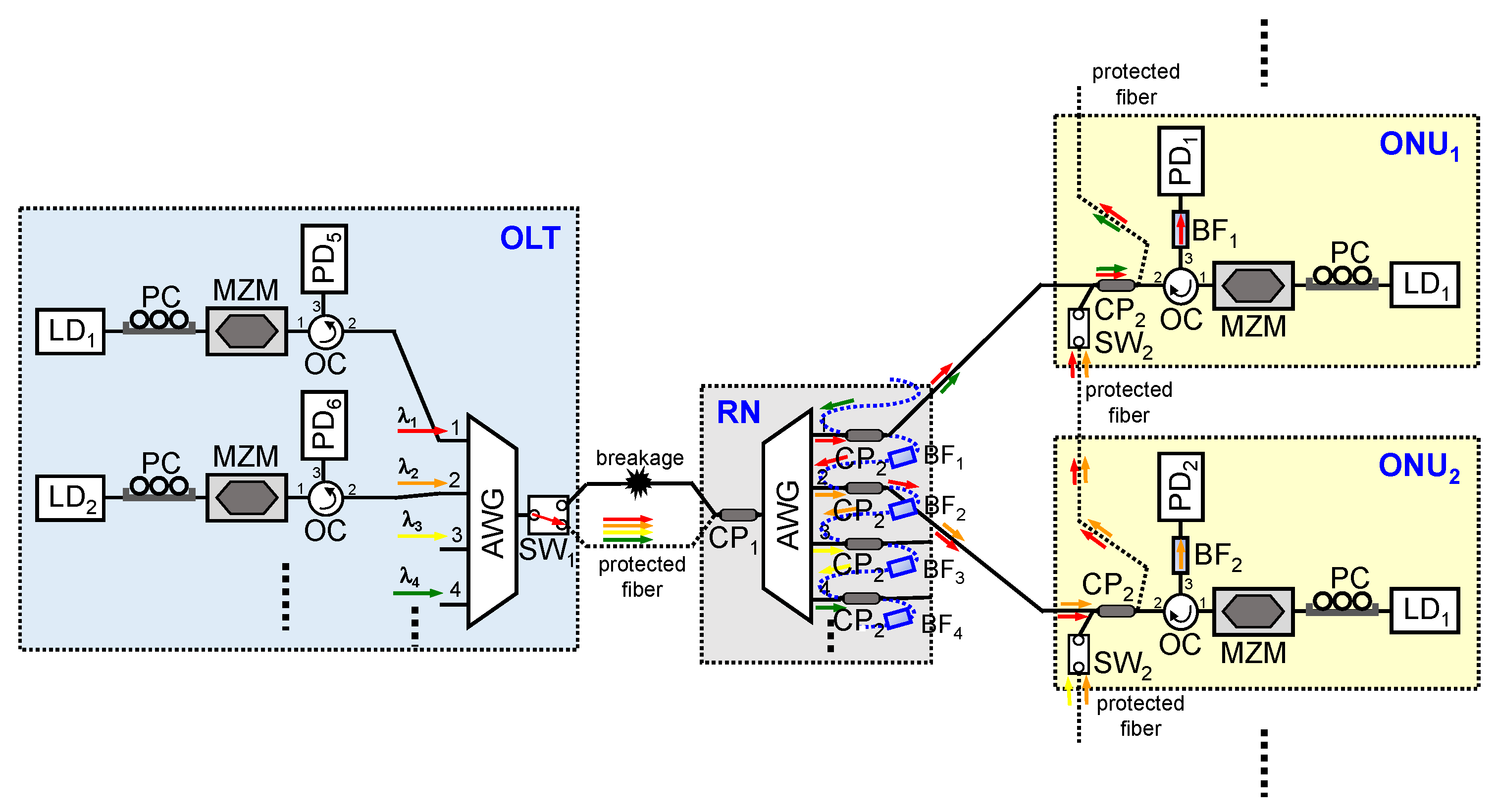
In order to understand the proposed fault operation mechanism in the PON system, we assume that a fiber breakpoint occurs at the upper feeder fiber, as seen in
Figure 3. Then, all downlink and uplink data links between the OLT and all ONUs will be disconnected. At this moment, the OLT cannot detect any of the uplink signals from the distributed ONUs. Based on the basic network operation, the SW
1 of OLT will be changed to connect to the lower feeder fiber (protected fiber) through the medium access control (MAC) for downstream and upstream data relinks, depending on whether the PD of the entire OLT detects the upload signal. This signal switching judgment method is the simplest. Thus, in this data link state, none of the ONUs need to make any changes. In the demonstration, the switching time of SW will affect the reconnection time of bidirectional signal transmission in the proposed PON system, when a fiber break occurs. Due to the device limit, a switching time of 7 ms by the micro-electro-mechanical system (MEMS)-based SW is achieved in the experiment. Moreover, the switching time of the new SW can reach 1 ms currently. However, to achieve a faster switching time, we can use a 1 ms SW instead in the lab.
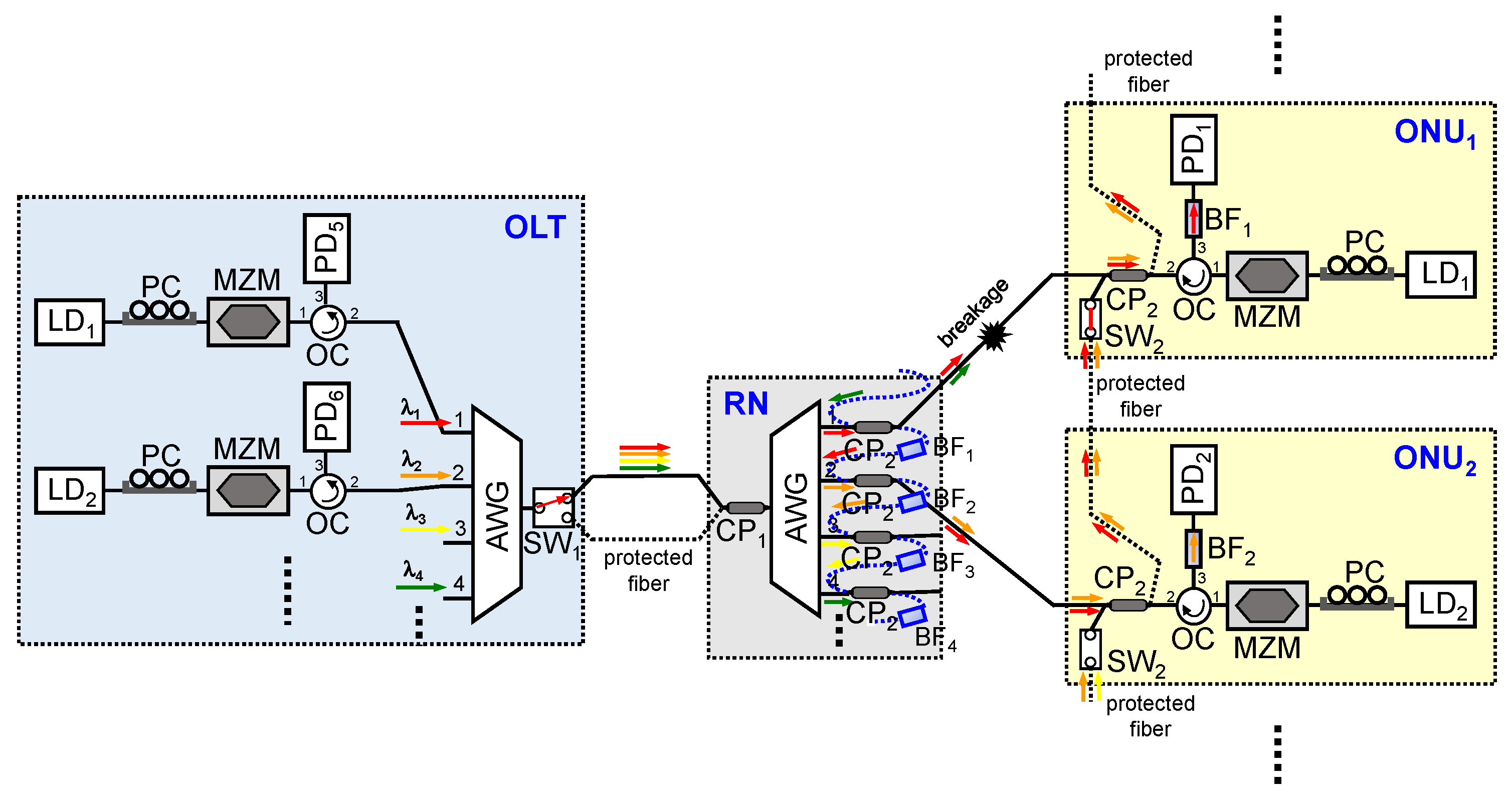
Furthermore, a fiber fault may occur on the distribution fiber between the RN and ONU
N. So, once a fiber breakpoint occurs as shown in
Figure 4, the downstream and upstream signal connections will be interrupted between RN and ONU
1. To restore the bidirectional access signal connection, as long as the SW
2 in ONU
1 is turned on through the MAC, the corresponding signal λ
1 can be reconnected at this time through the protected fiber between ONU
1 and ONU
2. This signal switching judgment method is also based on whether the PD detects the downstream signal. Although the downstream signal λ
1 cannot pass through the fiber breakpoint, it can pass through the BF
1 in RN and then into the ONU
2, as seen in
Figure 4. Then, the downstream λ
1 will be routed through the CP
2 in ONU
2, the protected fiber between ONU
1 and ONU
2, and SW
2 and CP
2 in ONU
1, respectively, for restoring the signal link between OLT and ONU
1. Similarly, the corresponding upstream signal λ
1 also can be linked through the same protected fiber path. That means that when a breakpoint occurs, the corresponding ONU
N only needs to turn on its own SW
2 to reconnect to the signal. Thus, this control mechanism is quite simple and convenient, as mentioned above.
As stated previously, using FSO technology to replace the protected fiber between two adjacent ONUs is also another option for signal relinking. Hence, we can add the optical FSO-related components in each ONU to replace protected fiber, as illustrated in
Figure 5. This also means that the FSO path is protected. To produce wireless FSO transmission, the proper fiber-type collimator (CM) with a small divergence angle can be applied in the ONU for enhancing the FSO link length [
15]. Here, even if there are interruption problems caused by fiber breakpoints like the situation in
Figure 4, we can still use the FSO method for signal reconnection. In the experimental setup, a CM with a 20 mm diameter is employed to transfer the downstream and upstream wavelengths to the FSO signal with a 7 mm spot beam. Additionally, the focus lengths of MC and the lens are 37.13 and 75 mm for demonstration. To execute the free space signal connection easily, a 2 m wireless transmission length is set for measuring FSO signal performance, as seen in
Figure 5. Moreover, the FSO signal connection is performed through a six-axis alignment platform. In short-distance transmissions, since the influence of a divergent CM is not significant, the FSO signal will be like a parallel light with a 7 mm spot. Therefore, the optical transmission must be more precisely calibrated in order to enter the fiber through the CM. As result, in the ONU, we can configure the protection operations on both sides to adopt FSO connections, or use optical fiber plus FSO based on the actual need.
Currently, we are demonstrating an eight-wavelength WDM-PON system. Even if the wavelength is increased to 16 channels, the insertion loss of AWG is still within 6 dB, which does not affect the current PON architecture. Even if we increase the channel number of AWG to 32, the maximum insertion loss is still about 7 dB. This should only add 1 dB to the overall loss of the PON network for each WDM channel. In addition, under atmospheric transmission, there will also be effects such as atmospheric vibration, noise, water vapor, scattering, and refraction. These will affect the distance and signal quality of wireless FSO transmission. Therefore, this above problem can be overcome by amplifying the optical power signal through an erbium-doped fiber amplifier (EDFA) or applying adaptive optics technology.
3. Experimental Results and Discussion
To demonstrate the WDM downstream and upstream signals, a tunable laser source (TLS) is applied as each WDM channel. A 40 GHz Mach–Zehnder modulator (MZM) is applied to generate a 25 Gbit/s OOK signal for downstream and upstream simultaneously. The polarization controller (PC) can adjust the polarization state to achieve optimal output power. In general, to obtain better optical power sensitivity for the detected WDM signal, an optical pre-amplifier is added in front of the PD. The optical pre-amplifier is used to replace the electrical RF amplifier and can improve the signal-to-noise ratio (SNR) and receiving sensitivity for the detected wavelength in the experiment for signal measurement. Generally, it is not necessary to add it to the ONU. First, we perform a bit error rate (BER) performance test of the 1530.33 nm wavelength with 25 Gbit/s OOK modulation and 2
15 − 1 pattern length to demonstrate both the downstream and upstream transmission, according to the proposed WDM network in
Figure 3 or
Figure 4 through the protected fiber, respectively. The 25 Gbit/s OOK modulation signal is produced and decoded through a BER tester. In the setup, a total length of the feeder and distribution fibers of 25 km is used for the normal and self-protection state for proof of concept. Furthermore, the 1530.33 nm output power is set to 5 dBm after leaving both the OLT and ONU. To avoid nonlinear effects after 25 km fiber transmission, the recommended power of <10 dBm can be calculated (optimal range: 0~7 dBm) when the 25 Gbit/s OOK modulation signal is applied. Hence, the 5 dBm output power of downstream or upstream wavelength would not induce nonlinear effects, such as four-wave mixing (FWM), stimulated Brillouin scattering (SBS), stimulated Raman scattering (SRS), etc.
Figure 6 shows the 25 Gbit/s OOK BER performances at the 1530.33 nm wavelength measured as the downstream and upstream signals after 25 km fiber transmission without using dispersion compensation, respectively. The received power sensitivities for the downstream and upstream traffic of 1530.33 nm are both −33.5 dBm at the forward error correction (FEC) threshold (BER ≤ 3.8 × 10
−3). Thus, a power budget of 38.5 dB can be achieved in the presented WDM-PON system. When the BER is between 10
−8 and 10
−9, the detected power sensitivity of both the downstream and upstream wavelengths is −28.5 dBm. The two insets are the corresponding eye diagrams of the downstream and upstream signals at the same detected power of −33.5 dBm below the FEC level, respectively. In addition, the corresponding eye is open and identifiable for decoding the modulation signal, as seen in
Figure 6.
Next, we can estimate the total insertion losses of the downstream and upstream traffic in the PON network. The downstream signal will pass through a 25 km total SMF length (0.2 × 25 = 5 dB), a WDM MUX (6 dB), a CP
1 (3 dB), two CP
2 (2 × 3 = 6 dB), an OC (0.5 dB), and a BF (3 dB), and then enters the PD at normal link status, respectively, as seen in
Figure 2. Moreover, the upstream signal will pass through a 25 km total fiber transmission length (0.2 × 25 = 5 dB), two WDM MUX (2 × 6 = 12 dB), a CP
1 (3 dB), a CP
2 (3 dB), an SW
1 (1 dB), and an OC (0.5 dB), and then enters the PD after leaving the ONU, respectively. Hence, the total insertion losses of the downstream and upstream signals are 23.5 and 24.5 dB. When the fault protection mechanism is operating, the downstream and upstream signals will pass through the same additional components of SW
2 (1 dB), two CP
2 (2 × 3 = 6 dB), and BF (3 dB), respectively, as shown in
Figure 4. Here, the total insertion losses of the downstream and upstream signals will become 29.5 and 30.5 dB. Based on the above power loss calculations, the overall loss of the designed WDM-PON system can be less than the power budget obtained. That means that the detected power sensitivity of the 1530.33 nm channel can meet the FEC requirement.
Then, we select eight WDM wavelengths of 1530.33 to 1535.82 nm with 0.8 nm channel spacing for the BER measurement of downstream and upstream traffic simultaneously.
Figure 7a,b present the measured 25 Gbit/s OOK BERs of eight selected WDM signals for the downstream and upstream wavelengths after 25 km fiber transmission, respectively. All BERs measured at both downstream and upstream wavelengths in
Figure 7a,b are below the FEC target after transmissions through the 25 km fiber link length. The corresponding power sensitivities of the downstream and upstream signals both measured from −33.5 to −28.5 dBm below the FEC threshold, as shown in
Figure 7a,b, respectively. Moreover, as the 25 Gbit/s OOK signal moves toward longer wavelengths, the corresponding optical power sensitivity will become smaller. According to the obtained power sensitivities, the power budgets of the downstream and upstream signals are both between 33.5 and 38.5 dB. Therefore, all the power budgets are larger than the total insertion loss of the PON system for delivering PON traffic.
When we use a WDM-PON system with the architecture shown in
Figure 5, the 25 Gbit/s OOK BER performance also can be measured through the 25 km SMF transmission and 2 m FSO link length. First, for BER measurements, we apply the wavelength of 1530.33 nm for both the downstream and upstream signals.
Figure 8 exhibits the measured 25 Gbit/s OOK BERs of both downstream and upstream channels. The detected power sensitivities of the downstream and upstream signals are both at −32.5 dBm under the FEC target. The corresponding power sensitivities of the downstream and upstream signals are −27 and −27.5 dBm in the BER range of 10
−8 and 10
−9. Moreover, the two insets are the corresponding eye diagrams of the 1530.33 nm downstream and upstream channels within the FEC limit. The eyes can be seen clearly and decoded, as displayed in
Figure 8.
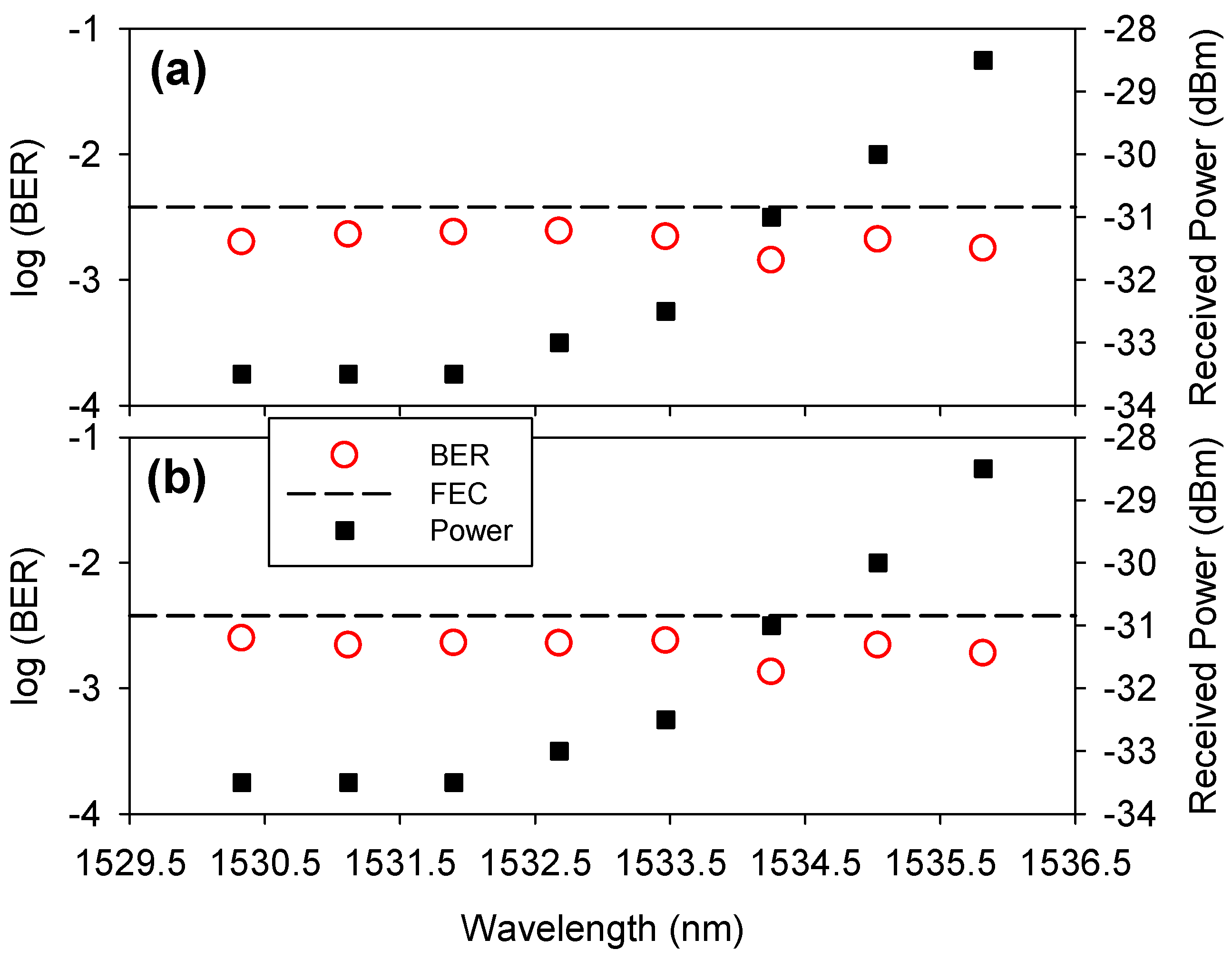
Next, the downstream and upstream channels of the selected eight WDM wavelengths from 1530.33 to 1535.82 nm are applied to the PON architecture in
Figure 5 for the measurement of corresponding power sensitivity. Consequently, the corresponding optical power sensitivities of the downstream and upstream signals measured between −33 and −28 dBm and −32.5 and −28.5 dBm, respectively, when the BER was lower than 3.8 × 10
−3 (FEC target), as seen in
Figure 9a,b. The corresponding power budgets of the downstream and upstream signals are achieved between 33 and 38 dB and 33.5 and 37.5 dB, respectively. The total insertion losses of the downstream and upstream channels induced through the PON network in
Figure 5 are also 29.5 and 30.5 dB, when the FSO signal transmitted is aligned for accurate data linkage. As mentioned before, we still have the minimum redundant power budgets of 3.5 (33 − 29.5) and 3 dB (33.5 − 30.5) for the wireless downstream and upstream links in the self-protected PON system in
Figure 5. According to the previous FSO study [
24], a redundant budget of 3 dB can support nearly 200 m wireless FSO transmission under pure atmosphere status, when the FSO signal has been accurately connected. Once the experimental setup for FSO transmission is placed outdoors, multiple atmospheric factors will cause the BER performance to deteriorate. In this demonstration, we propose the FSO technology to provide another signal reconnection protection scheme in the PON system for proof of concept. In addition, to extend the FSO link length, maybe an optical amplifier can be used in the ONU to increase its output power and compensate the insertion loss.
Adding some optical components to the proposed WDM-PON architecture in
Figure 3 and
Figure 5 will increase system costs. However, to achieve and provide the function of self-healing of fiber breakpoints to avoid signal interruption, it is necessary and important to add optical components to the PON network for users. In the demonstration, while the proposed network architecture increases the cost and component losses, it is still possible to perform bidirectional 25 Gbit/s OOK signal transmissions without dispersion compensation within a sufficient power budget. If we apply the lower insertion loss of AWG [
25] in the PON network, the total insertion loss could be improved to increase the power budget. Here, we only propose a new WDM-PON transmission system architecture to avoid fiber breakage. In the proposed PON system, the capacity of the downstream and upstream signals can be applied from 2.5 Gbit/s to 100 Git/s. However, the signal capacity and its corresponding fiber transmission distance are still required as the basis. Therefore, we apply a 25 Gbit/s OOK modulation rate to demonstrate the signal performance of the WDM-PON architecture designed for proof of concept.
4. Conclusions
In summary, a self-protected WDM-PON system was designed and experimentally demonstrated to avoid the fiber breakage on the feeder fiber or distribution fiber. To achieve self-protected function, the OLT, RN, and ONU modules were needed for the redesign to accommodate the bidirectional downstream and upstream traffic links via the protected fiber or FSO link path in the proposed PON architecture. Thus, two self-healing fiber access systems through protected fiber connections and FSO path links were proposed to protect against fiber faults, respectively. To investigate the downstream and upstream channel performances, a 25 Gbit/s OOK modulation signal was applied on each WDM channel for the BER measurement. Here, eight wavelengths of 1530.33 to 1535.82 nm with 0.8 nm channel spacing were applied, serving both as downstream and upstream signals for demonstration.
For the first proposed PON network with a protected fiber connection, the corresponding power sensitivities of the downstream and upstream signals both ranged from −33.5 to −28.5 dBm below the FEC threshold (BER ≤ 3.8 × 10⁻³) after transmission through a 25 km fiber link. So, the corresponding power budgets of 33.5 to 38.5 dB were obtained according to their power sensitivities. Moreover, the total insertion loss of the downstream and upstream channels in the first proposed PON were 29.5 and 30.5 dB when the fault protection operated to route the protected traffic link. As a result, the obtained power budget was higher than the total insertion loss.
For the second self-restored WDM-PON system with a protected FSO link, the obtained power sensitivities of the downstream and upstream signals were between −33 and −28 dBm and −32.5 and −28.5 dBm, respectively. Thus, the corresponding power budgets were also between 33 and 38 dB and 33.5 and 37.5 dB, respectively. However, based on the present minimum redundant power budgets of 3.5 and 3 dB for the downstream and upstream links, the FSO link length would be limited. To increase the FSO link between two ONUs, maybe an optical amplifier can be applied in the ONU to amplify the FSO output power for the data link. As a result, regardless of whether we used fiber- or FSO-type protection mechanisms, the proposed WDM-PON could effectively perform fiber breakpoint protection operations.
Compared with the previous studies [
1,
2,
3,
4,
5], the proposed WDM-PON has a simple operation mode that can achieve self-healing operations to avoid fiber breakpoints by only using the original PD in the OLT and each ONU. Moreover, the designed PON architecture also provides alternative protected paths through the fiber and FSO methods for downstream and upstream reconnection against fiber faults.
Therefore, the proposed WDM-PON network architecture can also be applied to B5G/6G mobile network connections. Each ONU also can be used as a B5G/6G base station (BS) for wireless signal transmission. In addition, each ONU can provide the FSO signal connection to deliver network-secured transmissions.


 ,
, 