1. Introduction
The eye-safe infrared wavelength of around 1.5 μm [
1,
2] and the mid-infrared spectral region of 3–5 μm both exhibit high atmosphere transmittance, making them suitable for various applications, including ranging, radar, remote sensing, medicine, the military, etc. [
3,
4,
5]. The direct generation of such wavelengths, e.g., Er-doped lasers [
6], is usually a difficult process for obtaining a high energy output. Therefore, OPO is a key method for generating such lasers through nonlinear frequency conversion [
7], offering excellent output power and spectral characteristics [
8,
9].
Several nonlinear crystals can be used in OPO, such as periodically poled LiNbO
3 (PPLN), ZnGeP
2 (ZGP), KTiOPO
4 (KTP), and KTiOAsO
4 (KTA) [
10,
11,
12]. However, PPLN is limited by its thickness, making it difficult to generate laser pulses with high energy. For ZGP crystals, mature 1 μm Nd-based lasers are not suitable tools for reaching a high average output power due to their strong crystal absorption. ZGP could obtain a high output power or energy [
10,
13], but it generally uses 2 μm lasers as pumps, which are relatively immature and limit further improvements in energy. Although KTP has a high damage threshold, large nonlinear coefficient, and wide acceptance angle, its mid-infrared output is low due to its absorption peak at 3.4 μm [
14]. As an isomorph of KTP, KTA has the advantages of a wider transparency range, a higher nonlinear coefficient, and better physical and chemical properties, making it more suitable for generating high-power and high-repetition infrared lasers. In as early as 1994, G.A. Rines et al. used KTP as an OPO crystal to obtain a 450 mJ 1.57 μm laser with a pulse repetition frequency (PRF) of 10 Hz [
15]. However, the average power was only 4.5 W, and mid-infrared lasers could not be attained due to the strong absorptance of KTP in the mid-infrared spectral region. In 1998, M.S. Webb et al. demonstrated a sustained average signal power of 33 W at 1534.7 nm, equivalent to a pulse energy of 330 mJ [
16]. The beam quality and idler laser were not mentioned. To obtain idler light output at the same time, in 2010, J. Liu et al. utilized a Y-cut KTA OPO pumped with a Nd:YAG laser to generate a 151 mJ eye-safe laser at 1.505 μm and 53 mJ mid-IR at 3.632 μm [
17]. The average powers of the signal and idler were relatively low, only 1.5 W and 0.5 W, respectively, owing to the 10 Hz repetition rate. In 2013, with an X-cut KTA, outputs of 33.8 mJ and 89.7 mJ at 3.46 μm and 1.54 μm were achieved by Q. Liu et al., respectively [
18]. For the Nd:YAG master oscillator power amplifier (MOPA) system, as the pump operated at a repetition rate of 100 Hz, the average power of the signal and idler did not exceed 10 W. In 2021, J. Meng constructed a 100 Hz, high-energy KTA crystal-based OPO system and achieved 178 mJ and 64 mJ signals at 1.53 μm and 3.47 μm, respectively, with a PRF of 100 Hz [
19]. Such KTA OPOs with a high pulse energy usually operate at repetition rates below 100 Hz; thus, the average power was maintained at a low level.
In this work, we pumped KTA OPO with a 300 Hz Nd:YAG MOPA laser system to simultaneously achieve high-power short-infrared and mid-infrared laser outputs. For the KTA OPO with a plane-parallel cavity, the output powers at 1.536 μm and 3.467 μm were 51.1 W and 15.9 W, respectively, with corresponding beam quality factors of Mx2 = 38 and My2 = 40 for the signal. To the best of our knowledge, these are the highest reported signal and idler powers for a KTA OPO at high repetition rates, and such a high-infrared laser output is rare in pulsed KTA OPO operation. For the KTA OPO with a ring cavity, the signal and idler output powers were reduced to 33.9 W and 8.7 W, respectively; however, the beam quality factors for the signal significantly improved to Mx2 = 5.3 and My2 = 7.9.
2. Experimental Setup
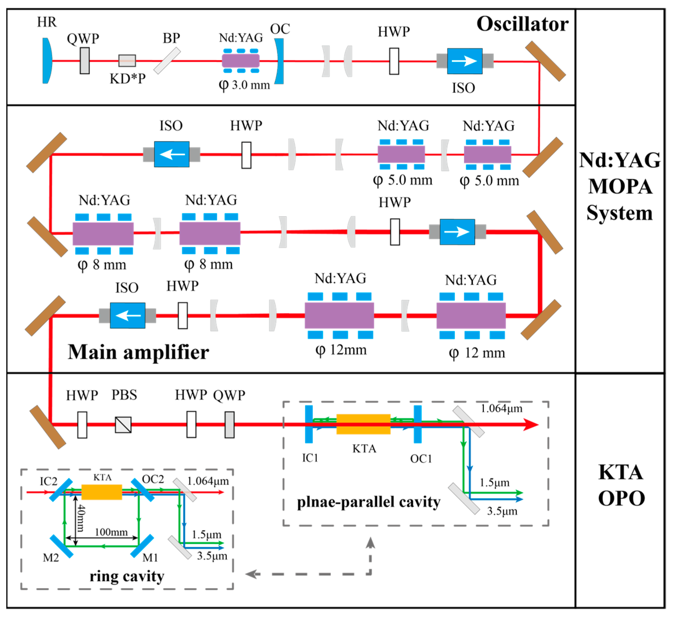
Figure 1 shows the experimental setup of the high-power KTA OPO system. The pump source was a 300 Hz, 1064 nm Nd:YAG MOPA system, consisting of a side-pumped Nd:YAG laser oscillator and three-stage amplifiers. The Nd:YAG crystal, 808 nm laser diode arrays, and heat sink were integrated into a commercial module. All the Nd:YAG modules were side-pumped using 808 nm laser diode arrays, which were operated in a quasi-continuous wave (QCW) mode with a pulse width and PRF of 250 μs and 300 Hz, respectively. For the OPO, a plane-parallel cavity was used to enhance efficiency, while a ring cavity was employed to improve the beam quality.
The master oscillator of the Nd:YAG MOPA system operated at a PRF of 300 Hz, Q-switched with a KD*P electro-optic modulator (EOM). To ensure that the cavity was stable and compact, the oscillator utilized a convex–concave resonator, with the concave mirror acting as the output coupler (OC), featuring a transmittance of 60% at 1.064 μm. The convex mirror (HR) was coated for high reflectance at 1064 nm. Considering the effect of the thermal lens, the selected radii of the convex and concave mirrors (HR) were 500 mm and 1000 mm, respectively. The EOM was placed on the side of the convex mirror, but not close to the convex lens, to prevent damage being caused by the small beam spot around the convex mirror. The corresponding Q-switch delay was set at 220 μs. A 0.6% Nd-doped side-pumped Nd:YAG module with a rod diameter of 3 mm and length of 78 mm was positioned close to the output mirror so that the laser rod could be fully utilized because the fundamental-mode radius near the output mirror was slightly smaller than the crystal diameter and varied very little over the entire rod length. In addition, this design ensured that the laser operation was insensitive to pump-induced lens fluctuations, thus providing a fine seed with near-fundamental-mode oscillation for subsequent amplifications.
The amplifiers of the MOPA system increased the laser power to several hundred watts. Every stage comprised two diode side-pumped Nd:YAG modules with a 90° quartz rotator placed between them to compensate for the thermally induced birefringence. The sizes of the Nd:YAG rods increased progressively across the stages: φ5 × 112 mm, φ8 × 146 mm, and φ12 × 167 mm. The module’s peak pump powers of the three amplification stages were 6 kW, 10 kW, and 10 kW, respectively. In addition, the end face of each crystal rod had parallel cutting angles of 2° to reduce the negative effects of self-excited oscillation.
The diameter of the output laser beam of the MOPA system was controlled to 9 mm before entering the KTA OPO. Additionally, the OPO pump power was changed using a polarization beam splitter (PBS) and HWP at the maximum output power, which ensured a consistent beam quality, pulse width, beam diameter, and directivity. The X-cut KTA can operate with the non-critical phase matching (NCPM) scheme, which offers a wide acceptance angle without walk-off and permits the use of a longer KTA crystal. Finally, an X-cut KTA (θ = 90°,φ = 0°) crystal with a size of 10 mm × 10 mm × 33 (length) mm without coating was selected. The OPO cavity configurations used in this study are shown in
Figure 1. The input mirror (IC1) of the plane-parallel cavity was coated with high transparency (HT) at 1.064 μm and high reflection at 1.5–1.6 μm, while the output mirror (OC1) was coated with 50% reflectivity at 1.5–1.6 μm and HT at 1.064 μm and 3.3–3.5 μm. The cavity length was as short as possible so that the OPO efficiency could be higher. As for the ring cavity, the two reflective mirrors M1 and M2 were the same as the input mirror (IC2), coated with HT at 1.064 μm and high reflection at 1.5–1.6 μm, and the output mirror (OC2) had 50% transmittance at 1.4–1.65 μm and high transmittance at 1.064 μm and 3.3–3.5 μm. The ring cavity length was 280 mm due to cavity structure limitations. Moreover, all mirrors had flat surfaces.
3. Results and Discussion
The average output power of the Nd:YAG oscillator is shown in
Figure 2a. The maximum output power was 3.0 W with a beam quality of M
x2 = 1.06, M
y2 = 1.06, as shown in
Figure 2b, and the inset shows the beam profile of the Nd:YAG oscillator, which indicates that the oscillator operated in a near-fundamental-mode state. The performance of the three-stage single-pass amplifiers of the Nd:YAG MOPA system is shown in
Figure 2c. From the curves in
Figure 2c, a total output power of 212 W with a pulse width and PRF of 14.1 ns and 300 Hz was finally achieved, respectively. The beam quality factors at the maximum output power were M
x2 = 3.4, M
y2 = 3.2, as depicted in
Figure 2d, and the corresponding beam profile is shown in the inset.
The output laser of the Nd:YAG MOPA system was then collimated to a diameter of 9 mm using a beam expander to match the size of the KTA crystal. Although the pump power density is much lower than the KTA crystal damage threshold (600 MW/cm
2), a repetition rate of 300 Hz induced significant thermal effects, leading to severe wavefront distortions when the pump beam diameter was reduced and amplifying the destructiveness of localized hot spots. Therefore, the beam size was maintained at a large diameter to prevent crystal damage. The KTA crystal was installed into copper blocks and water-cooled at approximately 20 °C with a temperature control accuracy of 0.1 °C. For plane-parallel cavity, the cavity length was kept as short as possible to lower the threshold and it was ultimately set to 70 mm due to the limitation of the long crystal heat sink and the size of the mirror frame. Despite the sensitivity of the plane cavity to disturbances, its compact architecture and low diffraction losses make it useful in high-power OPO applications. Finally, two dichroic mirrors were employed to separate the pump, signal and idler, allowing precise power measurement. The pump threshold of OPO was about 30.9 W, and the output powers of the signal and idler are shown in
Figure 3a1. When the pump power reached 207 W, the average power of the signal and idler was 51.1 W (170 mJ) and 15.9 W (53 mJ), corresponding to a conversion efficiency of 24.7% and 7.7%, respectively, as shown in
Figure 3b1. As the pump increased, the increase in the conversion efficiency gradually slowed down. The results represented a compromise between the conflicting goals of a high conversion efficiency and large beam radius. The OPO efficiency was sacrificed in exchange for more pump injections and stable operation at high-energy output levels, while simultaneously avoiding damage to crystals and other optical devices. To the best of our knowledge, these are the highest average output powers for the 1 μm pumped KTA OPO (signal + idler). As shown in
Figure 3c1, the M
2 factors of the signal were M
x2 = 38 and M
y2 = 40, and the inset shows the corresponding beam profile. The large pump spot size helps to avoid crystal damage but can lead to a higher OPO threshold and degraded beam quality. The Fresnel number was several hundreds and much larger than the number of approximately 0.5–2.0 when the resonator operated in the TEM
00 mode. Thus, the mode discrimination of the plane-parallel cavity was insufficient and many mode patterns existed, leading to a poor beam quality. For applications such as LiDAR, the poor beam quality increased the scattering and divergence of the laser beam, reducing the system’s ranging accuracy and distance. Therefore, a complex beam expansion system was designed and applied to ranging systems, where the laser beam was expanded and reshaped to 150 mm in diameter, in order to reduce the beam divergence and propagation distortion.
Additionally, although the single-pass pumping operation resulted in a conversion efficiency lower than the highest reported values of double-pass pumping, we aimed to avoid the damage caused to components by the increased power density in the standing wave cavity during double-pass pumping.
Though plane-parallel resonators can achieve high-power laser output, certain applications require lasers with both high power and beam quality. Thus, a ring resonator with a cavity length of 280 mm was established to balance power and beam quality. The OPO pump threshold increased to 50.0 W. According to the models in [
20,
21], the pump wave is assumed to comprise a Gaussian spatial intensity distribution. The coupled wave equations can be solved using Runge–Kutta algorithms. It is possible to vary the parameters of the pump beam and the OPO in the numerical model. The calculated pump thresholds of the plane-parallel and ring cavities were 34.5 W and 52.5 W, respectively, which reflects the increased threshold of the ring cavity. The maximum output power dropped to 33.9 W (113 mJ) and 8.7 W (29 mJ) for the signal and idler, respectively, as shown in
Figure 3a2, when the pump was 162.0 W, corresponding to a conversion efficiency of 20.9% and 5.4%, as shown in
Figure 3b2. The M
2 factors of the signal at the maximum output were M
x2 = 5.9 and M
y2 = 7.3, and the beam quality measurement and corresponding beam profile are shown in
Figure 3c2. If the pump increased further, the mirror IC would be damaged, and the output decreased rapidly as the damage area expanded. Although the mirrors used in the two cavities were bought from the same company and customized to meet an identical damage threshold, the IC of the ring cavity was obviously easier to damage; this could occur in the coating process, resulting in a lower damage threshold for the IC of the ring cavity. Limited by damage to the mirror, the maximum conversion efficiency of the ring cavity in the experiment was lower than that of the plane-parallel cavity, but, at the same pump-power-to-threshold ratio, the conversion efficiencies of the two cavities were similar. For example, when the pump power was about three times the threshold, the signal conversion efficiency of both cavities was about 20%. Thus, the ring cavity efficiency could still be improved, provided that the damage problem can be properly addressed.
As observed from the insets of
Figure 3c1,c2, the signal of the ring cavity had a better spatial intensity distribution than that of the plane-parallel cavity, and the beam quality significantly improved. This is due to the fact that the plane-parallel cavity exhibits a larger Fresnel number, and the ring cavity helps suppress competition from higher-order modes, leading to a better spatial distribution and beam quality. The improved beam quality of the ring cavity made it an ideal laser radiation for illumination and ranging at long distances. It is worth mentioning that the rotated-image singly resonant twisted rectangle (RISTRA) cavity, a type of non-planar ring cavity, has an additional 90° image rotation compared with the planar ring cavity and is effective in improving the beam quality of the critical-phase-matching OPO [
22,
23]. The case of non-critical phase matching without walk-off, e.g., the KTA OPO in our experiment, is worth exploring, and the RISTRA cavity may be a better alternative to the planar ring cavity. In future experiments, the role of seed injection technology in improving the beam quality and conversion efficiency will be explored, with attempts to combine it with non-planar ring cavities to achieve a stable OPO output with a high beam quality.
For the OPO ring cavity, the spectral characteristics of the pump, signal, and idler were measured using high-precision spectrometers (AQ6370D and AQ6377, YOKOGAWA, Tokyo, Japan), and the central wavelengths were 1064.5 nm, 1535.9 nm, and 3467.3 nm, respectively, as shown in
Figure 4. The corresponding linewidths were 0.15 nm, 0.3 nm, and 1.5 nm.
Finally, the pulse shapes were recorded using an indium gallium arsenide detector (Thorlabs PDA10CF-EC, for pump and signal), an MIR detector (MIP-10–100M-F-M4, Vigo, for idler), and an oscilloscope (Tektronix MSO64B), as shown in
Figure 5. When the ring cavity OPO operated at the maximum power, the pulse widths of the signal and idler were 11.9 ns and 14.4 ns, respectively. The signal pulse duration was slightly shorter than the pump, while the idler showed a broader pulse width owing to the different detector parameters.


