Article

Sub-Nanosecond, Room-Temperature, Mid-IR Fe:ZnSe Gain-Switched Laser: Experimental Characterization and Modeling

Department of Physics, University of Alabama at Birmingham, 1720 2nd Ave. S. ESH 4100, Birmingham, AL 35294-1170, USA
*
Authors to whom correspondence should be addressed.
These authors contributed equally to this work.
Photonics 2025, 12(3), 254; https://doi.org/10.3390/photonics12030254
Submission received: 12 February 2025 / Revised: 7 March 2025 / Accepted: 10 March 2025 / Published: 12 March 2025

Abstract

We present the modeling and experimental characterization of a room-temperature, sub-nanosecond, gain-switched (GS) Fe:ZnSe laser operating at 4.4–4.8 μm. As pump sources, we used a 2.79 µm Q-switched Cr:Er:YSGG laser with a pulse duration of 52 ns and the 2.98 μm idler of a Nd:YAG pumped KTA-OPO system with a pulse duration of 9 ns. The shortest pulse durations were measured to be 1.4 ns and 0.7 ns under excitation by the Cr:Er:YSGG laser and KTA-OPO system, respectively. The developed Fe:ZnSe laser model showed good agreement with the experimental results. Optimization of the laser parameters based on model simulations suggests that an Fe:ZnSe microchip laser configuration could be achieved with a pulse duration of ~250 ps and an efficiency of ~20%.

1. Introduction

The mid-IR spectra range, often called the “molecular fingerprint” region, spans wavelengths from 2 to 15 µm. Within this region lie several windows of high atmospheric transparency which allow radiation to pass through with minimal signal loss [1,2]. Additionally, many organic and inorganic molecules exhibit strong absorption within this region. Laser sources generating powerful coherent radiation in the mid-IR spectral range are important for a variety of scientific and industrial applications, including remote sensing [3], molecular spectroscopy, environmental monitoring [1,2,4], material processing [5], medicine [6,7], and defense [8,9]. Mid-IR lasers are also promising pump sources for laser systems with emission wavelengths extended to a longer mid-IR region. Among them are pump sources for optical parametric chirped-pulse amplification (OPCPA) systems [10], pump sources for Ce3+-doped selenide glass lasers [11], as well as CO2 lasers and amplifiers [12]. Despite the demand, effective laser sources operating within this temporal and spectral domain remain limited.
II-VI semiconductors doped with iron ions offer exceptional possibilities for generating and amplifying coherent radiation over a broad 3.4–8 µm spectral range [13,14]. Spectroscopic and laser characteristics of binary A2B2 and ternary (A2B2)C4 compounds doped with iron ions have been studied for dozens of years and summarized in recent reviews [15,16,17] and the references therein. In this active media group, the best laser characteristics are obtained in Fe2+:ZnSe crystals, enabling tunability over the 3.6–5.3 µm spectral range [4,18].
There are two complementary approaches to the design of high-power or energy Fe:ZnSe lasers and amplifiers. The first is based on a unique feature of the Fe:ZnSe gain medium: its excellent energy storage capacity at cryogenic temperatures (57 µs luminescence lifetime at 77 K [15]). Therefore, cryogenic Fe:ZnSe lasers and amplifiers can be optically pumped by radiation of readily available continuous-wave Cr:ZnSe [19], Er:ZBLAN fiber [20,21], or free-running Er:YAG lasers [22,23,24]. Recent achievements include a passively mode-locked Fe:ZnSe laser with 732 fs pulses at a repetition rate of 100 MHz [25], CW output power of 9.2 W [19], a 105 W cryogenically cooled Fe:ZnSe laser operating at a 250 Hz repetition rate [26], and 4.6 mJ femtosecond chirped pulse amplifier based on cryogenically cooled Fe:ZnSe operating at 333 Hz [23].
Alternatively, room-temperature (RT) Fe:ZnSe lasers and amplifiers can be pumped with ns pulses in a gain-switched (GS) regime. Our group realized the first RT GS Fe:ZnSe laser in 2005 [27]. Since then, dozens of RT GS Fe:ZnSe lasers and amplifiers have been reported by multiple groups [15,16,17,28]. The most notable achievements include high (1.4 J) output energy GS Fe:ZnSe master oscillators pumped by a nanosecond-radiation (150 ns) HF laser [29], 60 mJ GS nanosecond Fe:ZnSe multipass amplifiers [30], and a 10 mJ, 220 ps (before pulse compression) multipass Fe:ZnSe chirped pulse amplifier (CPA) [17] and broad tunability across the mid-IR spectral range (3.6–5.3 µm) [4,18].
Sub-nanosecond optical pulses are difficult to realize. They are shorter than the typical pulse duration of Q-switched lasers (10–100 ns) but longer than the typical pulses of mode-locked lasers (~100 fs). Powerful sub-nanosecond pulses in the 3–5 μm spectral range are practically relevant for a wide array of scientific, environmental, and defense-related fields.
Several research groups have investigated the relaxation oscillation behavior of optical pulses in the gain-switched regime [18,30,31], which is characterized by distinct relaxation peaks. These relaxation spikes are typical characteristic features in GS lasers’ dynamics. The focus and novelty of our work are optimizing the first oscillation peak to enable lasing in the single-pulse, sub-nanosecond regime. Achieving this optimization allows for enhanced pulse quality and temporal control, enabling key applications in micromachining [32], materials processing [33], and pumping of CPA systems [10].
This paper reports on the modeling and experimental development of gain-switched Fe:ZnSe lasers operating at room temperature in the single-pulse regime, with sub-nanosecond pulse durations in the 4.4–4.8 µm spectral range. As pump sources, we used a 2.79 µm Q-switched Cr:Er:YSGG laser with a pulse duration of 52 ns and the 2.98 μm wavelength idler of a Nd:YAG laser pumped KTA-OPO system with a pulse duration of 9 ns.

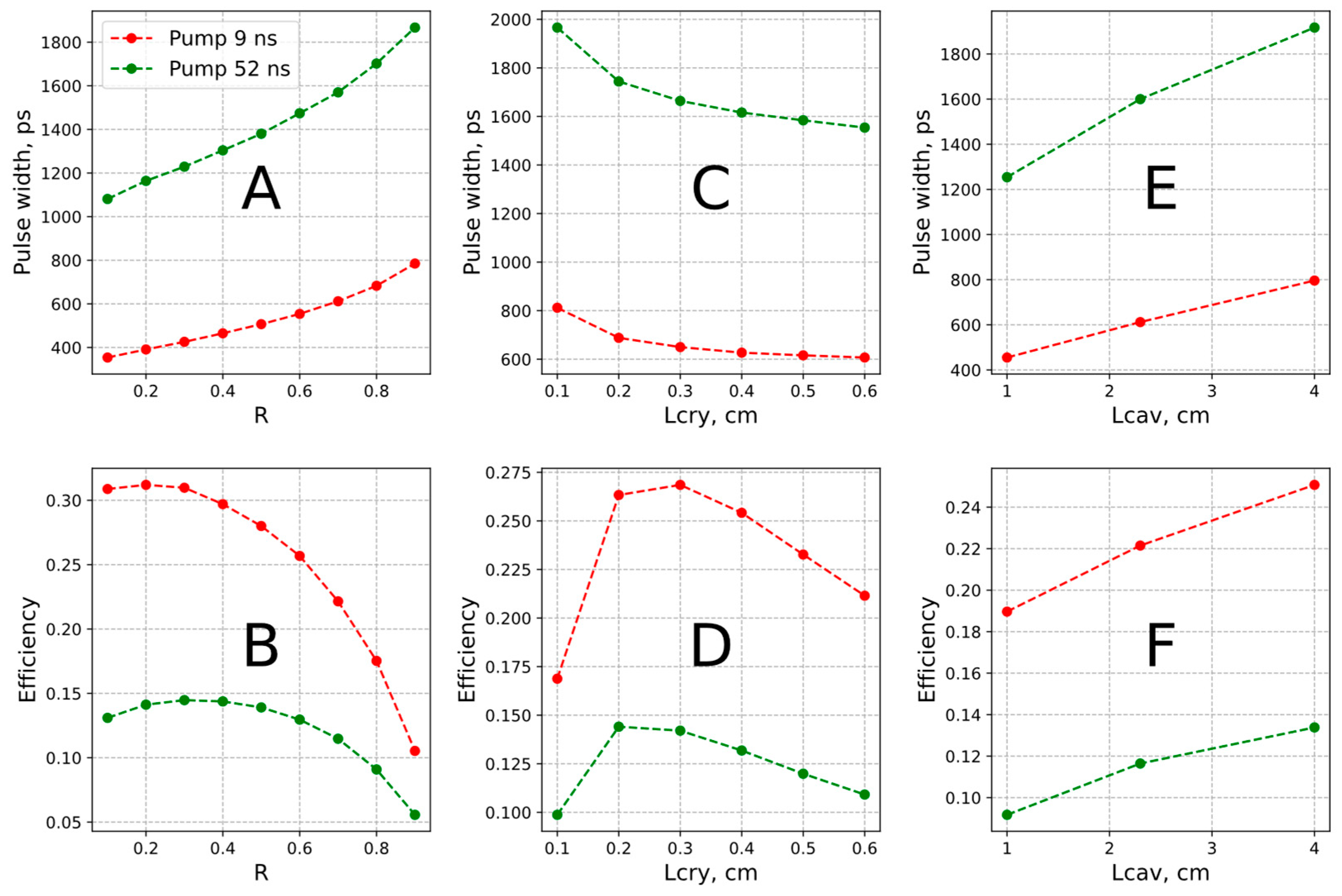
2. Modeling of Gain-Switched Fe:ZnSe Room-Temperature Laser

The laser model presented here relies on a one-dimensional rate equation approach [34] and encompasses the principal transitions depicted in Figure 1. When Fe2+ ions are introduced into a ZnSe crystal, the 5D free-ion ground state splits under the weak tetrahedral crystal field of II-VI semiconductors [35], forming two energy-level manifolds: a 5E doublet, which effectively serves as the ground state, and a 5T2 triplet. The amplification bandwidth of Fe:ZnSe is expanded by up to half its central wavelength thanks to the strong electron-phonon coupling, which makes this material highly attractive for broadband mid-IR tunability and ultrashort pulse generation. Figure 1A displays the Fe2+ absorption and emission cross-sections in ZnSe. In our model, the pump and lasing wavelengths were about 2.79–2.98 µm and 4.5 µm, respectively.
In Fe:ZnSe, vibronic sub-levels have short relaxation times, and consequently, the laser behaves like an effective two-level system. It offers a practical balance between accuracy and computational simplicity while still allowing distinct absorption and emission parameters. Figure 1B shows the key processes included in the model. The described transitions occur in the mid-infrared range, while all other transitions are spin-forbidden. The complete set of wave propagation and rate equations (Equation (1a)–(1e)) is as follows:
(1a)   I p z z = N 1 z σ p _ a b I p z α p a s s i v e p I p z (1b) I o + z z = N 1 z σ a b N 2 z σ e m I o + z α p a s s i v e o I o + z + β s p L c r N 2 z τ 2 (1c) I o z z = N 1 z σ a b N 2 z σ e m I o z + α p a s s i v e o I o z β s p L c r N 2 z τ 2 (1d) N 2 z t = N 1 z σ p _ a b N 2 z σ p _ e m I p z +                                       + N 1 z σ a b N 2 z σ e m I o + z + I o z N 2 z τ 2 (1e) N t o t a l = N 1 z + N 2 z
Equation (1a) describes the one-dimensional propagation of pump photon flux I p z . Here, N 1 z is the density of population in the ground state, and σ p _ a b is the absorption cross-section at the pump wavelength. The last term accounts for non-saturable passive losses. Equations (1b) and (1c) describe the intracavity radiation propagation in both directions. I o + z and I o z represent the intensities of the forward- and backward-propagating oscillation field, respectively, while σ a b and σ e m are the absorption and stimulated emission cross-sections at the oscillation wavelength. The coefficient α p a s s i v e o accounts for passive losses at the laser wavelength. The final term, β s p L c r N 2 z / τ 2 , represents the spontaneous-emission feed, where a fraction β s p of the spontaneously emitted photons at a rate A · L c r N 2 z / τ 2 is funneled into each laser mode, in which A and L c r are the mode area and thickness of the gain element, respectively. Equation (1d) is the rate equation for the upper laser level N 2 . The first term, N 1 z σ p _ a b N 2 z σ p _ e m I p z , represents the net pump-induced population flow into or out of N 2 . The second term, N 1 z σ a b N 2 z σ e m I o + z + I o z , represents the oscillation-induced population flow. The term N 2 z / τ 2 describes the non-radiative decay term from the upper laser level. Equation (1e) expresses the balance of the total density of Fe2+ ions N t o t a l over a distance z . Table 1 summarizes the definitions of the parameters and the values used in the simulations.
Within the equation system in Equation (2), we define the initial and boundary conditions. Both mirrors are assumed to be transparent at the pump wavelength. At the lasing wavelength, the back mirror at z = 0 acts as a high reflector (HR), whereas the output coupler (OC) at z = L c a v is partially reflective with a reflectivity R O C . Additionally, we included the diffractive cavity losses per round trip T d i f f to include the plane mirror cavity and divergence of laser oscillation. The numerical solution of differential equations employs the finite difference method, which couples the temporal increment to a chosen space step with a straightforward ratio ( Δ z = Δ t · c / n , where c is the speed of light and n is the refractive index):
I p z = 0 , t = I t , input   pump   photon   flux I o + z = 0 , t = I o z = 0 , t I o z = L c a v , t = T d i f f · R O C I o + z = L c a v , t I o u t t = 1 R O C I o + z = L c a v , t N 2 z , t = 0 = 0 N e s a z , t = 0 = 0 I o + z , t = 0 = 0 I o z , t = 0 = 0                

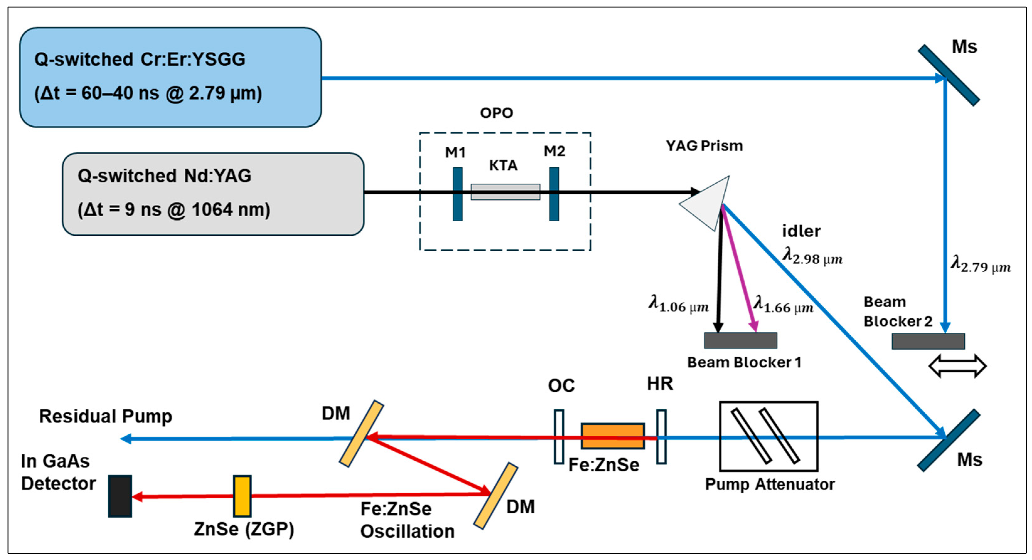
3. Experimental Set-Up

Our experiments used two different pump sources with pulse durations of 52 ns and 9 ns (see Figure 2). One of the pump sources was a homemade, electro-optically (EO) Q-switched Cr:Er:YSGG laser [36]. The flash lamp-pumped Cr:Er:YSGG laser operated at a repetition rate of 3 Hz. The maximum output energy was measured to be 120 mJ, with pulse durations as short as 40 ns. The pulse duration of the laser depends on the pump energy. However, 40 ns pulses caused optical damage to the coating of the La3Ga5SiO14 (LGS) crystal used as an electro-optical Q-switch of the Cr:Er:YSGG cavity [37]. Therefore, in our experiments, we limited the pump energy of the Cr:Er:YSGG laser so that the oscillation pulse duration was ~52 ns. The spatial profiles of the laser beams were measured using a Spiricon Pyrocam III-HR (Newport Corporation Ophir, North Logan, UT, USA).
The “long” 52 ns pulse duration of the Cr:Er:YSGG pump restricted the pulse duration and the output energy of the gain-switched Fe:ZnSe laser operating in the single-pulse regime. Therefore, in our studies, we used a Nd:YAG laser-pumped optical parametric oscillator. This system is commonly used to effectively generate nanosecond pulses in the 3 µm spectral range and could be used to pump an Fe:ZnSe laser. The idler from a Nd:YAG-pumped KTA-based OPO system was used as a second pump source in our experiments [38]. The KTA crystal was cut for phase-matching conditions for 1/3000 nm(e) + 1/1649 nm(o) = 1/1064 nm(o) interactions (θ = 64.7°, φ = 0°; Cristal Laser Co., Messein, France). Mirror M1 was a high reflector (HR) at 1647 nm and 2900–3000 nm, while mirror M2 was an HR at 1647 nm with a high transmitter (HT) at an idler wavelength 2900–3000 nm. In the non-selective cavity OPO, the spectrum of idler pulses was adjusted to be between 2950 nm and 2980 nm. The maximum output energy was measured to be 16 mJ with a 9 ns duration. Finally, a YAG prism was used to separate the idler, pump, and signal beams, with a beam blocker placed to block the pump and signal while allowing the idler to propagate. The transition between the pump lasers is illustrated by repositioning Beam Blocker 2 as shown in Figure 2.
The pump radiations were directed to the Fe:ZnSe laser using steering mirrors (Ms). A set of optical attenuators was used to control the incident pump energy. The Fe:ZnSe cavity consisted of a dichroic mirror (DM), an Fe:ZnSe gain element (IPG Photonics Corporation, Marlborough, MA, USA), and an OC (30%, 50%, and 70% reflectivity, respectively). In all experiments, the cavity length was set to 2.3 cm. As the gain element, we used a set of 1, 2, or 3 Fe:ZnSe crystals with antireflection (AR) coatings, an iron concentration of 1.1 × 1019 cm−3, and a thickness of 1.8 mm. After the Fe:ZnSe laser cavity, dichroic mirrors were used to filter out the residual pump radiation and direct the Fe:ZnSe emission toward a power meter, pyrocamera, and spectrometer. We used a 5 GHz InGaAs detector (DET08CL, Thorlabs Inc., Newton, NJ, USA) and a 6 GHz digital oscilloscope (TDS 6604, Tektronix Inc., Beaverton, OR, USA) to measure the pulse duration with a sub-ns resolution. Unfortunately, the spectral sensitivity of the fast InGaAs detector allowed measurements only at the second harmonic of the Fe:ZnSe laser radiation. We used quasi-phase matching in polycrystalline ZnSe crystal (or ZGP nonlinear crystal) for fast temporal detection of the mid-IR emission from the GS Fe:ZnSe laser. Considering only the temporal dependence of second-harmonic generation (SHG) in the fixed-field approximation, the intensity of the second harmonic was proportional to the squared intensity of the laser oscillation, where I ω t ~ I o s c 2 t [39]. In our experiments, the detected temporal profiles could be fitted well with a Gaussian shape. Therefore, the measured pulse duration at the second harmonic was multiplied by √2 to estimate the pulse duration at the fundamental wavelength.

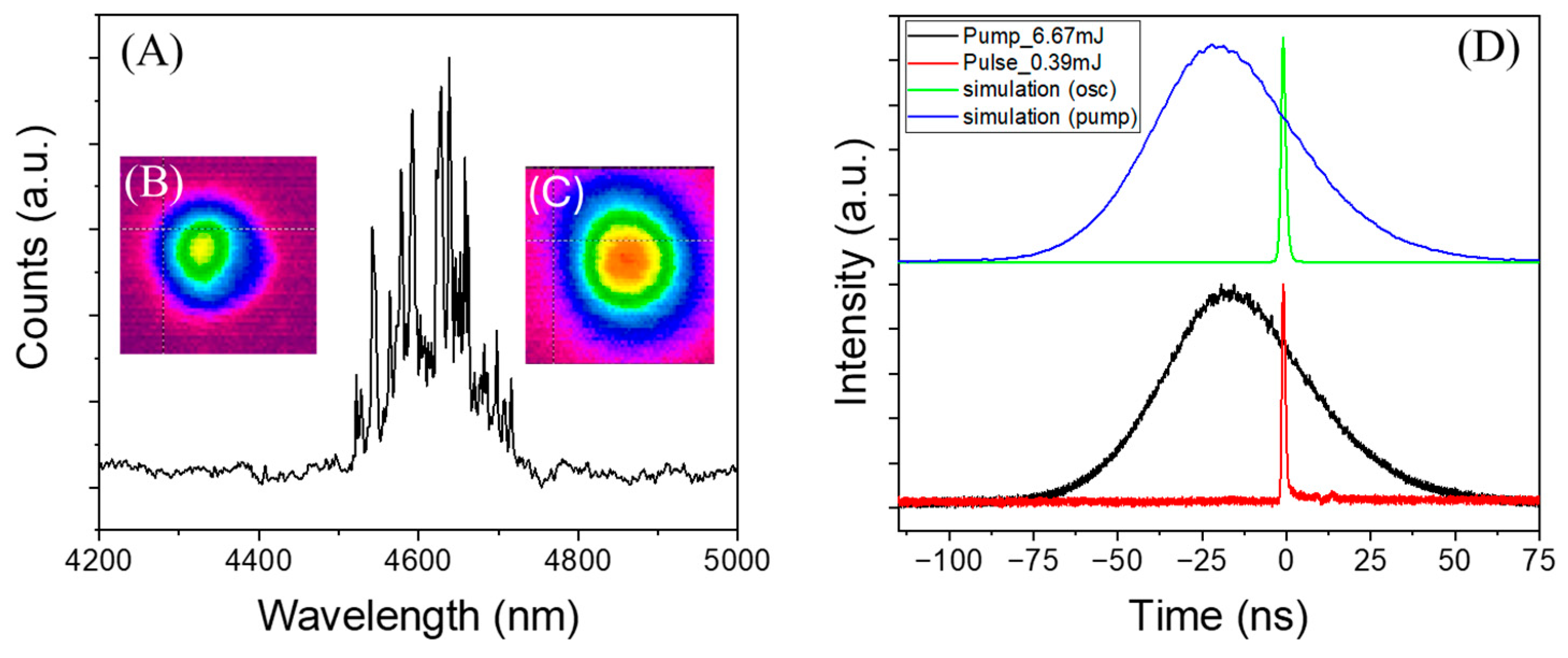
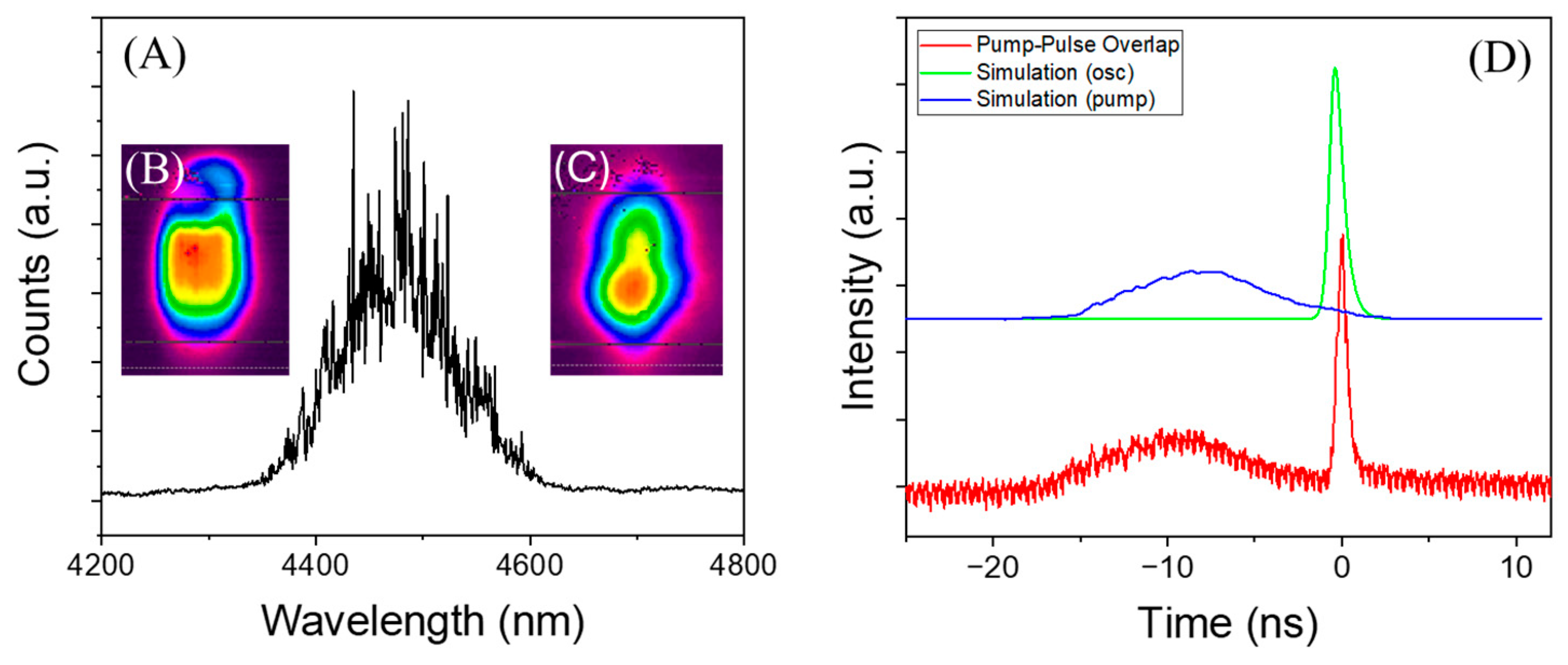
4. Results and Discussion

The spatial profile of the pump radiation from the Cr:Er:YSGG laser was close to a Gaussian shape with a pulse duration of 52 ns, as shown in Figure 3. The pump beam was reshaped to form a spot 3.25 mm in diameter (Figure 3B) at the gain element. Initially, three Fe:ZnSe crystals were used as the gain element with a total crystal thickness L c r y = 5.4 mm. In this configuration, the laser threshold was measured to be E t h = 3 mJ. With an increase in pump energy, the laser oscillated in a single-spike regime until E p u m p = 6.7 mJ. The output energy of the Fe:ZnSe laser was measured to be 0.39 mJ. Figure 3A presents the spectrum of the Fe:ZnSe laser. As can be seen from the figure, the peak oscillation wavelength was centered at 4.64 μm with a full width at half maximum (FWHM) of approximately 120 nm. Figure 3C illustrates the near-Gaussian beam profile of the Fe:ZnSe oscillation. A further increase in pump energy resulted in higher output but with multi-pulse operation. The temporal profiles of the pump and laser pulses are shown in Figure 3D. The FWHM pulse duration was estimated to be 1.7 ns.
The temporal profiles of the laser simulation are also shown in Figure 3D. The duration of the simulated pulse was equal to 1.6 ns. In this simulation, a pump energy of 6.8 mJ with a beam diameter of 2.9 mm was used. As can be seen from the figure, the pulse shape and delay time of the laser simulation closely match the experimental data. In this simulation, the only variable parameter was the coupling coefficient of spontaneous emission (β), which was set to 10−10. However, variation in β in the range from 10−7 to 10−11 resulted in a variation in the pulse duration and output energy of approximately 20%.
Interestingly, a decrease in the reflectivity of the output coupler to 50% and 32% resulted in a reduction in the maximum pump energy for the single-spike oscillation to 5.7 mJ and 5.3 mJ, respectively. As a result of these restrictions, the maximum output energy of a single pulse was measured to be 0.3 mJ with R = 50% and 0.2 mJ with R = 32%. With output couplers of 50% and 32% in the same cavity, the pulse duration was estimated to be 1.4 ns.
To achieve oscillation with a shorter pulse duration, we tested a pump system based on a KTA-based OPO system with a pulse duration of 9 ns. The beam shape of the idler pulses at 2.8 μm is shown in Figure 4B. As shown in the figure, the beam quality of the KTA-OPO idler was poor due to several factors, including the phase-matching conditions and a short OPO cavity length. However, the efficiency of the Fe:ZnSe laser under OPO excitation was comparable to its efficiency under Cr:Er:YSGG laser excitation. In our experiments, we tested two focusing configurations of the pump radiation. The first alignment formed a pump beam with a size of 3.3 × 4.6 mm2 on the surface of the gain element, which consisted of two 1.8 mm Fe:ZnSe crystals. The output coupler was 70%. In these experiments, the highest output energy was measured to be 1.05 mJ in 0.89 ns pulses under a pump energy of 16 mJ. Although we did not measure the temporal stability of the oscillation pulses, the close values of the Fe:ZnSe pulse durations under KTA-OPO excitation suggest good temporal stability. The measured pulse durations in three trials were 622 ps, 649 ps, and 625 ps prior to ×√2 corrections. The spectra of the Fe:ZnSe laser and output beam profile are shown in Figure 4A and 4C, respectively. In this experiment, the total crystal thickness of the gain elements was smaller than in previous experiments. This resulted in a smaller influence of the overlapping of the emission and absorption bands and a shift of the oscillation wavelength to a shorter wavelength (4500 nm). The temporal profiles of the pump and GS laser pulses are also shown in Figure 4D. As one can see from the figure, the pump and oscillation pulses practically did not overlap. After reshaping the pump beam to a smaller size (2.7 × 3.8 mm2), we achieved the shortest FWHM pulse duration of 0.7 ns, but the output energy was also smaller (0.75 mJ).
The temporal profiles of the laser simulation are also shown in Figure 4D. The duration of the simulated pulse was approximately 840 ps. As can be seen in the figure, the simulation results were in good agreement with the experimental data for both the excitation laser and for the different thicknesses of the gain element.
Figure 5 shows the simulation results with variations in the output coupler reflectivity, crystal length, overall cavity length, and pump pulse duration. Figure 5A,B displays the simulation results for two different pump durations, with the output coupler reflectivity ranging between 0.1 and 0.9. All other parameters except the pump energy were fixed; the crystal length was set to 0.54 cm, the cavity length was 2.3 cm, and the Fe2+ concentration was 1.1 × 1019 cm−3. In each case, the pump energy was increased to the highest energy level of a single-spike operation. As one can see, the decrease in the output couples’ reflectivity resulted in a shortening of the spike duration. Interestingly, in the case of 9 ns pump pulses, the laser efficiency was approximately constant for the output coupler variation between 0.1 and 0.7. Figure 5C,D shows a variation in the thickness of the gain element with all the same parameters and the OC reflectivity fixed at 0.7. While there was a small decrease in the pulse duration for longer crystals, the difference for the 0.3 mm and 0.6 mm gain elements was insignificant. Figure 5C demonstrates that extending the cavity length increased the pulse width. The impact of the pump duration on the oscillation dynamics was investigated using ideal Gaussian pump signals with a varying FWHM. One could mention earlier that a 9 ns pump pulse generally outperformed the longer pulses. Figure 6 reinforces this observation, showing that a shorter pump pulse yielded a shorter laser output pulse with higher energy and improved efficiency in the range studied. It is worth mentioning that with a sixfold difference in pump pulses, the laser pulses differed by a factor of three. This outcome underscores the advantage of reducing the pump pulse duration.
Finally, Figure 7 shows the simulated temporal profiles of the Fe:ZnSe laser, demonstrating a pulse width of ~250 ps. This simulation assumed the microchip Fe:ZnSe laser configuration when the back mirror and output coupler with a reflectivity R = 0.3 were deposited on a 3 mm-long Fe:ZnSe crystal. The passive and diffractive losses (0.21 and 0.92 cm−1, respectively), along with the dopant concentration (1.1 × 1019 cm−3), remained unchanged. When considering 9 ns excitation pulses, 37× time pulse compression and 20% maximum laser efficiency with a 1.8 mJ single-pulse output at a 3 mm pump beam diameter were expected based on our simulations.

5. Conclusions

This study investigated the modeling and experimental characterization of a room-temperature, sub-nanosecond, gain-switched Fe:ZnSe laser operating at 4.4–4.8 μm. The experimental results demonstrate that the shortest pulse durations achieved were 1.4 ns and 0.7 ns when pumped by radiations of the 2.79 µm Q-switched Cr:Er:YSGG laser (52 ns) and the 2.98 μm idler of a KTA-OPO system (9 ns), respectively. The developed laser model agreed well with the experimental data, validating its accuracy in describing the laser dynamics. Furthermore, model-based optimization indicates that an Fe:ZnSe microchip laser configuration could achieve pulse durations as short as ~250 ps with an estimated efficiency of ~20%. These findings highlight the potential for further optimization of Fe:ZnSe lasers for high-performance mid-infrared applications.

Author Contributions

Conceptualization, V.F. and S.M.; methodology, S.G., D.D., D.M., V.F. and S.M.; software, D.D.; validation, S.G., D.D., D.M. and V.F.; writing—review and editing, S.G., D.D., D.M., V.F. and S.M. All authors have read and agreed to the published version of the manuscript.

Funding

This research was funded by the U.S. Department of Energy (DE-SC0018378) and the National Institute of Environmental Health Sciences (1P42ES027723-01A1).

Institutional Review Board Statement

Not applicable.

Informed Consent Statement

Not applicable.

Data Availability Statement

The data underlying the results of this study can be obtained from the corresponding author upon request.

Acknowledgments

The authors would like to thank Kiyoshi Yamamoto for the valuable discussions.

Conflicts of Interest

The authors declare no conflicts of interest.

Abbreviations

The following abbreviations are used in this manuscript:
ARAntireflection
CPAChirped-pulse amplification
DMDichroic mirror
EOElectro-optical
FWHMFull width at half maximum
GSGain-switched
HRHigh reflector
HTHigh transmitter
KTAPotassium titanyl arsenate
LGSLanthanum gallium silicate
Mid-IRMiddle infrared
OCOutput coupler
OPCPAOptical parametric chirped-pulse amplification
OPOOptical parametric oscillator
RTRoom temperature
SHGSecond-harmonic generation
YAGYttrium aluminum garnet
YSGGYttrium scandium gallium garnet
ZBLANZirconium barium lanthanum aluminum sodium fluoride
ZGPZinc germanium phosphide

References

  1. Schliesser, A.; Picqué, N.; Hänsch, T.W. Mid-Infrared Frequency Combs. Nat. Photon. 2012, 6, 440–449. [Google Scholar] [CrossRef]
  2. Maidment, L.; Schunemann, P.G.; Reid, D.T. Molecular Fingerprint-Region Spectroscopy from 5 to 12 µm Using an Orientation-Patterned Gallium Phosphide Optical Parametric Oscillator. Opt. Lett. 2016, 41, 4261–4264. [Google Scholar] [CrossRef] [PubMed]
  3. Walsh, B.M.; Lee, H.R.; Barnes, N.P. Mid Infrared Lasers for Remote Sensing Applications. J. Lumin. 2016, 169, 400–405. [Google Scholar] [CrossRef]
  4. Fjodorow, P.; Frolov, M.P.; Korostelin, Y.V.; Kozlovsky, V.I.; Schulz, C.; Leonov, S.O.; Skasyrsky, Y.K. Room-Temperature Fe:ZnSe Laser Tunable in the Spectral Range of 3.7–5.3 µm Applied for Intracavity Absorption Spectroscopy of CO2 Isotopes, CO and N2O. Opt. Express 2021, 29, 12033. [Google Scholar] [CrossRef]
  5. Haglund, R.F.; Dygert, N.L.; Johnson, S.L.; Schriver, K.E.; Park, H.K. Processing of Polymer and Organic Materials by Tunable, Ultrafast Mid-Infrared Lasers. In Pacific International Conference on Applications of Lasers and Optics; Laser Institute of America: Orlando, FL, USA, 2008; pp. 658–663. [Google Scholar] [CrossRef]
  6. Amini-Nik, S.; Kraemer, D.; Cowan, M.L.; Gunaratne, K.; Nadesan, P.; Alman, B.A.; Miller, R.J.D. Ultrafast Mid-IR Laser Scalpel: Protein Signals of the Fundamental Limits to Minimally Invasive Surgery. PLoS ONE 2010, 5, e13053. [Google Scholar] [CrossRef]
  7. Yue, W.; Zhang, Y.; Shi, L.; Chen, T.; Chen, J.; Wu, B.; Zhang, S.; Shu, R.; Shen, Y. Porcine Skin Ablation Using Mid-Infrared Picosecond Pulse Burst. Results Opt. 2022, 9, 100309. [Google Scholar] [CrossRef]
  8. Hinton, G.D. Infrared Countermeasures Test and Evaluation. ITEA J. 2006, 13–14. [Google Scholar]
  9. Keller, J. Northrop Grumman to Upgrade Obsolescence in Infrared Countermeasures Sensors for Aircraft Missile Warning. Mil. Aerosp. Electron. 2022. [Google Scholar]
  10. Elu, U.; Steinle, T.; Sánchez, D.; Maidment, L.; Zawilski, K.; Schunemann, P.; Zeitner, U.D.; Simon-Boisson, C.; Biegert, J. Table-Top High-Energy 7 µm OPCPA and 260 mJ Ho:YLF Pump Laser. Opt. Lett. 2019, 44, 3194. [Google Scholar] [CrossRef]
  11. Fjodorow, P.; Frolov, M.P.; Leonov, S.O.; Denker, B.I.; Galagan, B.I.; Sverchkov, S.E.; Koltashev, V.V.; Plotnichenko, V.G.; Sukhanov, M.V.; Velmuzhov, A.P. Mid-Infrared Laser Performance of Ce3+—Doped Selenide Glass. Opt. Express 2021, 29, 27674. [Google Scholar] [CrossRef]
  12. Tovey, D.; Pigeon, J.; Tochitsky, S.; Louwrens, G.; Ben-Zvi, I.; Martyshkin, D.; Fedorov, V.; Karki, K.; Mirov, S.; Joshi, C. Lasing in 15 Atm CO2 Cell Optically Pumped by a Fe:ZnSe Laser. Opt. Express 2021, 29, 31455. [Google Scholar] [CrossRef] [PubMed]
  13. Martinez, A.D.; Martyshkin, D.V.; Camata, R.P.; Fedorov, V.V.; Mirov, S.B. Crystal Field Engineering of Transition Metal Doped II-VI Ternary and Quaternary Semiconductors for Mid-IR Tunable Laser Applications. Opt. Mater. Express 2015, 5, 2036. [Google Scholar] [CrossRef]
  14. Frolov, M.P.; Korostelin, Y.V.; Kozlovsky, V.I.; Leonov, S.O.; Skasyrsky, Y.K. Tunable in the Range of 4.5–6.8 µm Room Temperature Single-Crystal Fe:CdTe Laser Pumped by Fe:ZnSe Laser. Opt. Express 2020, 28, 17449. [Google Scholar] [CrossRef]
  15. Mirov, S.B.; Moskalev, I.S.; Vasilyev, S.; Smolski, V.; Fedorov, V.V.; Martyshkin, D.; Peppers, J.; Mirov, M.; Dergachev, A.; Gapontsev, V. Frontiers of Mid-IR Lasers Based on Transition Metal Doped Chalcogenides. IEEE J. Sel. Top. Quantum Electron. 2018, 24, 1–29. [Google Scholar] [CrossRef]
  16. Dormidonov, A.E.; Firsov, K.N.; Gavrishchuk, E.M.; Ikonnikov, V.B.; Kononov, I.G.; Kurashkin, S.V.; Podlesnykh, S.V.; Savin, D.V. Suppression of Transverse Parasitic Oscillation in Fe:ZnSe and Fe:ZnS Lasers Based on Polycrystalline Active Elements: A Review. Phys. Wave Phen. 2020, 28, 222–230. [Google Scholar] [CrossRef]
  17. Pushkin, A.; Potemkin, F. Refining the Performance of Mid-IR CPA Laser Systems Based on Fe-Doped Chalcogenides for Nonlinear Photonics. Photonics 2023, 10, 1375. [Google Scholar] [CrossRef]
  18. Fedorov, V.; Martyshkin, D.; Karki, K.; Mirov, S. Q-Switched and Gain-Switched Fe:ZnSe Lasers Tunable over 3.60–5.15 µm. Opt. Express 2019, 27, 13934. [Google Scholar] [CrossRef]
  19. Mirov, S.; Fedorov, V.; Martyshkin, D.; Moskalev, I.; Mirov, M.; Vasilyev, S. High Average Power Fe:ZnSe and Cr:ZnSe Mid-IR Solid State Lasers. In Advanced Solid State Lasers; OSA: Berlin, Germany, 2015; p. AW4A.1. [Google Scholar] [CrossRef]
  20. Pushkin, A.V.; Migal, E.A.; Uehara, H.; Goya, K.; Tokita, S.; Frolov, M.P.; Korostelin, Y.V.; Kozlovsky, V.I.; Skasyrsky, Y.K.; Potemkin, F.V. Compact, Highly Efficient, 21-W Continuous-Wave Mid-Infrared Fe:ZnSe Coherent Source, Pumped by an Er:ZBLAN Fiber Laser. Opt. Lett. 2018, 43, 5941. [Google Scholar] [CrossRef]
  21. Liang, X.; Zhou, S.; Liu, Z.; Bao, B. Modeling and Analysis of Actively Q-Switched Fe: ZnSe Laser Pumped by a 2.8 µm Fiber Laser. Optoelectron. Lett. 2023, 19, 513–518. [Google Scholar] [CrossRef]
  22. Fedorov, V.V.; Mirov, S.B.; Gallian, A.; Badikov, D.V.; Frolov, M.P.; Korostelin, Y.V.; Kozlovsky, V.I.; Landman, A.I.; Podmar’kov, Y.P.; Akimov, V.A.; et al. 3.77–5.05 µm Tunable Solid-State Lasers Based on Fe2+—Doped ZnSe Crystals Operating at Low and Room Temperatures. IEEE J. Quantum Electron. 2006, 42, 907–917. [Google Scholar] [CrossRef]
  23. Kozlovsky, V.I.; Korostelin, Y.V.; Podmar’kov, Y.P.; Skasyrsky, Y.K.; Frolov, M.P. Middle Infrared Fe2+:ZnS, Fe2+:ZnSe and Cr2+:CdSe Lasers: New Results. J. Phys. Conf. Ser. 2016, 740, 012006. [Google Scholar] [CrossRef]
  24. Marra, Z.A.; Wu, Y.; Zhou, F.; Chang, Z. Cryogenically Cooled Fe:ZnSe-Based Chirped Pulse Amplifier at 4.07 µm. Opt. Express 2023, 31, 13447. [Google Scholar] [CrossRef] [PubMed]
  25. Pushkin, A.V.; Migal, E.A.; Tokita, S.; Korostelin, Y.V.; Potemkin, F.V. Femtosecond Graphene Mode-Locked Fe:ZnSe Laser at 4.4 µm. Opt. Lett. 2020, 45, 738. [Google Scholar] [CrossRef] [PubMed]
  26. Wu, Y.; Zhou, R.; Zhou, S.; Ren, H.; Zhang, S.; Wei, X.; Shang, J.; Wang, W.; Leng, M.; Dai, W.; et al. High Average Power (105 W) Fe:ZnSe Laser Pumped by Radiation of Laser Diode Side-Pumped Er:YAG Lasers. Opt. Lett. 2024, 49, 3476. [Google Scholar] [CrossRef]
  27. Kernal, J.; Fedorov, V.V.; Gallian, A.; Mirov, S.B.; Badikov, V.V. 3.9–4.8 µm Gain-Switched Lasing of Fe:ZnSe at Room Temperature. Opt. Express 2005, 13, 10608. [Google Scholar] [CrossRef]
  28. Leonov, S.; Frolov, M.; Korostelin, Y.; Skasyrsky, Y.; Kozlovsky, V. Gain-Switched Fe:ZnSe Laser Pumped by a Coupled-Cavity Q-Switched Er:ZrF4 Fiber Laser. Opt. Lett. 2023, 48, 2957. [Google Scholar] [CrossRef]
  29. Dormidonov, A.E.; Firsov, K.N.; Gavrishchuk, E.M.; Ikonnikov, V.B.; Kazantsev, S.Y.; Kononov, I.G.; Kotereva, T.V.; Savin, D.V.; Timofeeva, N.A. High-Efficiency Room-Temperature ZnSe:Fe2+ Laser with a High Pulsed Radiation Energy. Appl. Phys. B 2016, 122, 211. [Google Scholar] [CrossRef]
  30. Martyshkin, D.; Karki, K.; Fedorov, V.; Mirov, S. Room Temperature, Nanosecond, 60 mJ/Pulse Fe:ZnSe Master Oscillator Power Amplifier System Operating at 3.8–5.0 µm. Opt. Express 2021, 29, 2387. [Google Scholar] [CrossRef]
  31. Antonov, V.A.; Bukin, V.V.; Dolmatov, T.V.; Firsov, K.N.; Gavrishchuk, E.M.; Kononov, I.G.; Obraztsov, P.A.; Podlesnykh, S.V.; Ponarina, M.V.; Sirotkin, A.A.; et al. Single-Nanosecond-Pulse Lasing in Heavily Doped Fe:ZnSe. IEEE Photonics J. 2021, 13, 1500807. [Google Scholar] [CrossRef]
  32. Phillips, K.C.; Gandhi, H.H.; Mazur, E.; Sundaram, S.K. Ultrafast Laser Processing of Materials: A Review. Adv. Opt. Photon. 2015, 7, 684. [Google Scholar] [CrossRef]
  33. Malinauskas, M.; Žukauskas, A.; Hasegawa, S.; Hayasaki, Y.; Mizeikis, V.; Buividas, R.; Juodkazis, S. Ultrafast Laser Processing of Materials: From Science to Industry. Light Sci. Appl. 2016, 5, e16133. [Google Scholar] [CrossRef] [PubMed]
  34. Yamamoto, K.; Fedorov, V.V. Modeling of Sub-Nanosecond Fe:ZnSe Mid-IR Gain-Switched Laser Operating at Room Temperature. In Solid State Lasers XXXIII: Technology and Devices; Clarkson, W.A., Shori, R.K., Eds.; SPIE: San Francisco, CA, USA, 2024; p. 4. [Google Scholar] [CrossRef]
  35. Low, W.; Weger, M. Paramagnetic Resonance and Optical Spectra of Divalent Iron in Cubic Fields. I. Theory. Phys. Rev. 1960, 120, 2277. [Google Scholar] [CrossRef]
  36. Martyshkin, D.; Fedorov, V.; Hamlin, S.J.; Mirov, S. 350 mJ Electro-Optically Q-Switched 2.79 µm Cr:Er:YSGG MOPA. Opt. Express 2023, 31, 18525. [Google Scholar] [CrossRef] [PubMed]
  37. Lan, H.; Liang, F.; Lin, Z.; Yu, H.; Zhang, H.; Wang, J. Langasite Family Midinfrared Nonlinear Optical Oxide Materials: Structure, Property, and Applications. Int. J. Opt. 2017, 2017, 2980274. [Google Scholar] [CrossRef]
  38. Ghimire, S.; Danilin, D.; Martyshkin, D.; Fedorov, V.; Mirov, S. Room Temperature Sub-Nanosecond Fe:ZnSe Gain-Switched Laser Characterization and Modeling. In Solid State Lasers XXXIV: Technology and Devices; Clarkson, W.A., Shori, R.K., Eds.; SPIE: San Francisco, CA, USA, 2025; p. 55. [Google Scholar] [CrossRef]
  39. Dmitriev, V.G.; Gurzadjan, G.G.; Nikogosjan, D.N. Handbook of Nonlinear Optical Crystals, 3rd ed.; Springer Series in Optical Sciences; Springer: Berlin/Heidelberg, Germany, 2010; ISBN 978-3-642-08472-0. [Google Scholar]
Figure 1. (A) Absorption (solid red curve) and emission (dashed red curve) cross-sections of Fe:ZnSe gain media. The red arrow indicates excitation by radiation with a wavelength of approximately 2.8–2.9 µm, as used in the experiments. The long blue arrow represents the stimulated emission process. The oscillation wavelengths in the experiments shifted from the maximum of the emission cross-section due to a strong overlap between the absorption and emission bands. (B) Cavity geometry used in the numerical model along with the energy level diagram of Fe2+ ions in the tetrahedral field of ZnSe.
Photonics 12 00254 g001
Figure 2. Schematic diagram of the GS Fe:ZnSe room-temperature laser pumped by the emission from two homemade lasers: the EO Q-switched Cr:Er:YSGG laser and the idler from a KTA-based OPO. The mirrors (Ms) steer the high-reflector mirrors at the pump wavelength, and dichroic mirrors (DMs) are used to separate the pumps from the Fe:ZnSe emission.
Photonics 12 00254 g002
Figure 3. (A) Emission spectrum of the GS Fe:ZnSe laser. (B) Spatial profile of the electro-optically Q-switched Cr:Er:YSGG pump laser at the gain media face. (C) The beam profile of the GS Fe:ZnSe laser. (D) Temporal profiles of the Cr:Er:YSGG pump pulse (experimental = black, simulation = blue) and the Fe:ZnSe oscillation pulse (experimental = red, simulation = green).
Photonics 12 00254 g003
Figure 4. (A) Emission spectrum of the GS Fe:ZnSe laser. (B) Spatial profile of the idler from the KTA-OPO system at the gain media face. (C) The beam profile of the GS Fe:ZnSe laser. (D) Temporal profiles of the idler pump pulse (experimental = broad red; simulation = blue) and the Fe:ZnSe oscillation pulse (experimental = narrow red; simulation = green).
Photonics 12 00254 g004
Figure 5. Laser pulse width and efficiency as functions of OC reflectivity (A,B), crystal (gain medium) length (C,D), and overall cavity length (E,F).
Photonics 12 00254 g005
Figure 6. Pulse width and efficiency of the laser as a function of the Gaussian pump pulse duration.
Photonics 12 00254 g006
Figure 7. Temporal profiles of the pump pulse (blue dashed line for input and black dashed line for output) and numerically computed single-spike oscillation (red line) in an Fe:ZnSe microchip configuration.
Photonics 12 00254 g007
Table 1. Summary of parameters and their values used in the simulations.
Input Physical ParameterSymbolValueUnits
Crystal length L c r y 0.1–0.6cm
Cavity length L c a v 0.3–4.0cm
Output coupler reflectivity R o c 0.1–0.9unitless
Total Fe2+ concentration N t o t a l 1.1 × 1019cm−3
Lower manifold population density N 1 variablecm−3
Upper manifold population density N 2 variablecm−3
Pump wavelength λ p 2.98 (2.79)µm
Laser oscillation wavelength λ o 4.50 (4.65)µm
Absorption cross-section at   λ p σ p _ a b 0.96 (0.82)×10−18 cm2
Absorption cross-section at   λ o σ a b 0.100 (0.058)×10−18 cm2
Emission cross-section at   λ o σ e m 1.08 (0.94)×10−18 cm2
Non-saturable passive losses at  λ p α p a s s i v e p 0.04cm−1
Non-saturable passive losses at  λ o α p a s s i v e o 0.21cm−1
Pump photon flux I p variable[photon/(s·cm2)]
Laser oscillation flux propagating to the right I o + variable[photon/(s·cm2)]
Laser oscillation flux propagating to the left I o variable[photon/(s·cm2)]
Pump pulse duration at FWHM τ p 9 (52)ns
Upper-level lifetime τ 2 380ns
Refractive index at  λ p n p 2.44unitless
Refractive index at  λ o n o 2.43unitless
Spontaneous emission to laser oscillation mode coupling coefficient (oscillation seed) β s p 10−7–10−11unitless
Round trip oscillation diffractive losses T d i f f 0.92unitless
Disclaimer/Publisher’s Note: The statements, opinions and data contained in all publications are solely those of the individual author(s) and contributor(s) and not of MDPI and/or the editor(s). MDPI and/or the editor(s) disclaim responsibility for any injury to people or property resulting from any ideas, methods, instructions or products referred to in the content.

