1. Introduction
In recent years, high-order transverse mode laser outputs have garnered significant attention due to their unique polarization, amplitude, and phase characteristics, particularly in applications involving the mode-division multiplexing technique [
1], material processing [
2], power scaling [
3], the generation of vortex beams [
4], cylindrical vector beams [
5], and annular beams [
6]. Currently, numerous methods have been proposed for generating single high-order transverse mode lasers, which can be categorized into three main types: traditional bulk optical schemes, hybrid schemes combining bulk optics with fiber optics, and all-fiber schemes. These methods primarily utilize devices such as spatial light modulators [
7], spatial phase plates [
8], mode converters [
9,
10], fiber Bragg gratings (FBGs) [
11,
12,
13], polarization controllers [
14], and coherent polarization beam combining [
15] to achieve the desired outcomes. The bulky spatial light modulator eliminates its applicability to compact all-fiber lasers. Polarization-dependent elements (segmented delay devices, photonic crystal gratings, birefringent crystals, spatially varying wave plates, etc.) can also be used for the selective excitation of specific higher-order modes. However, they not only have bulky configurations, but also have poor scalability for general modes. The fiber Bragg grating mode selection method has high stability, but the grating itself is difficult to engrave and has high production costs. Although the offset splicing coupling mode selection method has relatively low efficiency, its structure is the simplest and most direct.
In conventional few-mode fibers, it is commonly believed that only a limited number of low-order modes, such as LP
01 and LP
11, are supported based on the weak guidance approximation. However, due to differences in polarization, these fibers can support more modes. As a result, even in typical two-mode fibers, at least six different fiber modes are supported. These modes are associated with slightly different propagation speeds, and when multiple modes coexist within the same fiber, the intensity distribution of higher-order modes across the fiber’s cross-section varies along its length. Furthermore, these modes may be influenced by changes in the surrounding environment. Small environmental variations can induce minor phase shifts between nearly identical eigenmodes, further contributing to changes in the cross-sectional intensity distribution of higher-order modes. This environmental sensitivity limits the practical applications of higher-order modes in certain fiber devices. At present, for high-order transverse modes of linear polarization, the output polarization is controlled by using fiber polarization controllers [
5,
16]. Although this method can obtain high-order transverse modes with linear polarization, it still poses certain challenges to the stability of the output. This limits their practical application in fiber optic devices [
17,
18].
In conclusion, to address the issue of unstable output of linearly polarized LP11 mode, we propose a linearly polarized LP11 mode fiber laser based on a polarization-maintaining fiber Bragg grating (PM-FBG) with an output power of 3.8 W. This laser achieves the conversion from LP01 to LP11 mode and maintains stable transmission of linearly polarized LP11 mode. First, the conversion from LP01 to LP11 mode was achieved through misaligned splicing. Then, by utilizing a customized pair of polarization-maintaining FBGs, the fiber laser was designed to output only a specific single-polarization mode, thus preserving the spatial stability of the LP11 mode. In the experiment, a polarization extinction ratio (PER) of 96.7% and a mode purity of 95.32% were achieved, realizing a fully fiber-based structure for single-polarization high-order transverse mode output. Moreover, the use of an all-PM fiber structure eliminated the need for a fiber polarization controller (PC), ensuring the laser’s excellent stability.
2. Experimental Setup
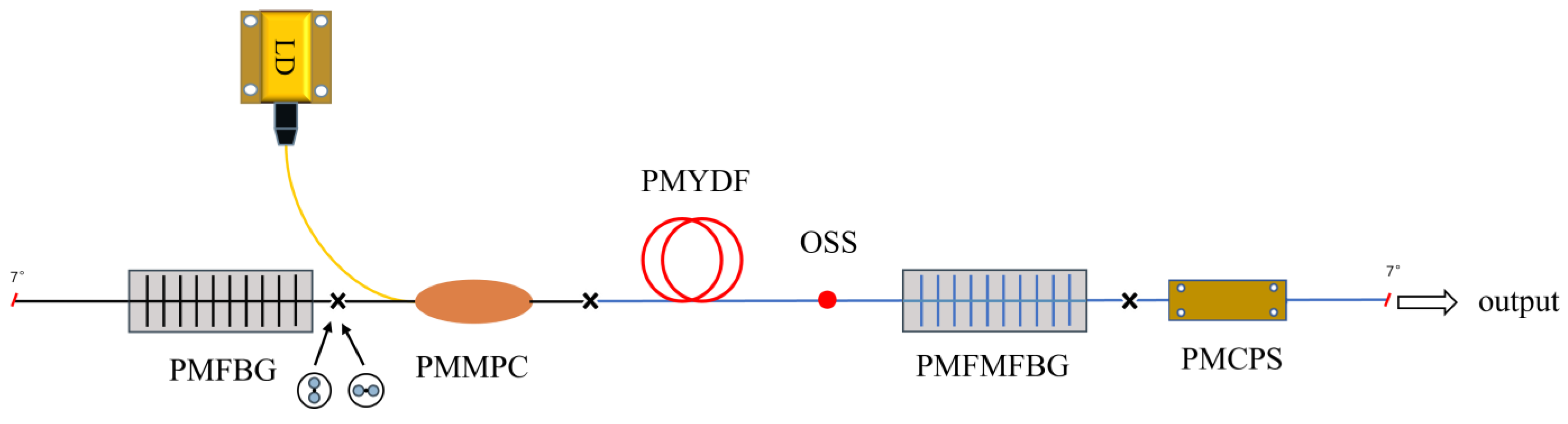
The experimental setup for the cladding-pumped single-polarization LP
11 mode Yb-doped fiber laser (YDFL) is illustrated in
Figure 1. A laser diode (LD) is spliced to the pump port of a (1 + 1) × 1 polarization-maintaining (PM) combiner. The total pump power is 25 W, with core and cladding diameters of the PM combiner being 10 μm and 125 μm, respectively. A 15 m long 20/400 PM Yb-doped fiber is used as the gain fiber, which has an absorption coefficient of 1.5 dBm
−1 at 976 nm. The numerical aperture (NA) of the gain fiber is 0.065. To match the reflection peak of the LP
01 mode, and ensure the output of the LP
11 mode, two different types of PM fibers are employed to inscribe fiber Bragg gratings (FBGs) in this experiment: a PM single-mode fiber inscribing the PMFBG and a PM few-mode fiber inscribing the PMFMFBG. These two types of gratings form the laser cavity. By rotating the axis by 90° during fusion splicing, the slow-axis alignment of the spectrum on the polarization-maintaining few-mode fiber Bragg grating (PMFMFBG) is achieved, ensuring the formation and output of linearly polarized beams. Subsequently, the LP
01 mode is converted to the LP
11 mode through offset splicing. Finally, the PMFMFBG is utilized as the output coupler for the linearly polarized LP
11 mode within the laser cavity, while most of the LP
01 mode is reflected back. The cladding power stripper (CPS) is created by chemically etching irregular pits on the cladding surface of the fiber, resulting in the leakage of the laser at the etched interface due to the failure to meet the total internal reflection conditions. Additionally, a 7° split angle was implemented at the fiber output end to prevent end-face reflection.
Based on the principle of polarization mode selection using polarization-maintaining (PM) gratings, this design involves specially configured grating parameters and a unique splicing technique. This ensures that the reflection spectra of the grating pair overlap only in one polarization direction, allowing only a single-polarization mode to oscillate within the resonator, thereby achieving linearly polarized laser output. The reflection spectrum of the PM fiber grating consists of the fast- and slow-axis reflection spectra, with the wavelength difference between these reflections determined by the birefringence coefficient of the PM fiber. The reflection wavelength difference can be expressed as follows [
19]:
where
represents the birefringence coefficient, and
denotes the grating period. For PM fiber Bragg grating (PMFBG), the value of
is 3 × 10
−4, and the value of
is 368 nm, so the value of
is calculated to be 0.221 nm. For PM few-mode fiber Bragg grating (PMFMFBG), the value of
is 4 × 10
−4, and the value of
is 368 nm, so the value of
is calculated to be 0.294 nm. In LP
01 mode, the fast-axis transmission peak of the PMFBG is aligned with the slow-axis reflection peak of the PMFMFBG to ensure linear polarization output within the laser cavity. Furthermore, since both FBGs exhibit high reflectivity for the LP
01 mode, they effectively filter out the output of the fundamental mode LP
01, thus guaranteeing high mode purity for the resulting linearly polarized LP
11 mode. The presence of the fundamental mode is one of the critical factors influencing the output power and polarization purity. A broadband light source is utilized to measure the transmission spectrum of the PMFBG and the reflection spectrum of the PMFMFBG, as shown in
Figure 2. Both the transmission and reflection peaks correspond to the fundamental mode, i.e., the LP
01 mode.
The reflectance measurement for the LP
01 mode at the PMFBG is 96.9%, while at the PMFMFBG, it is 90.2%. According to the normalized frequency
, the calculations are as follows: At a wavelength of 1064 nm, the PM single-mode fiber has a core diameter of 10 μm, a cladding diameter of 125 μm, and a numerical aperture (
) of 0.08. The normalized frequency
is calculated to be 2.36, indicating that this fiber can support only the fundamental mode. The PM few-mode fiber has a core diameter of 20 μm, a cladding diameter of 400 μm, and a numerical aperture (
) of 0.065. The calculated normalized frequency
is 3.84. In the weak guiding approximation, only the LP
01 and LP
11 modes can propagate in this fiber. The corresponding basic parameters are shown in
Table 1. For the generation of LP
11 mode, this experiment adopts the method of offsetting and splicing two PM few-mode fibers.
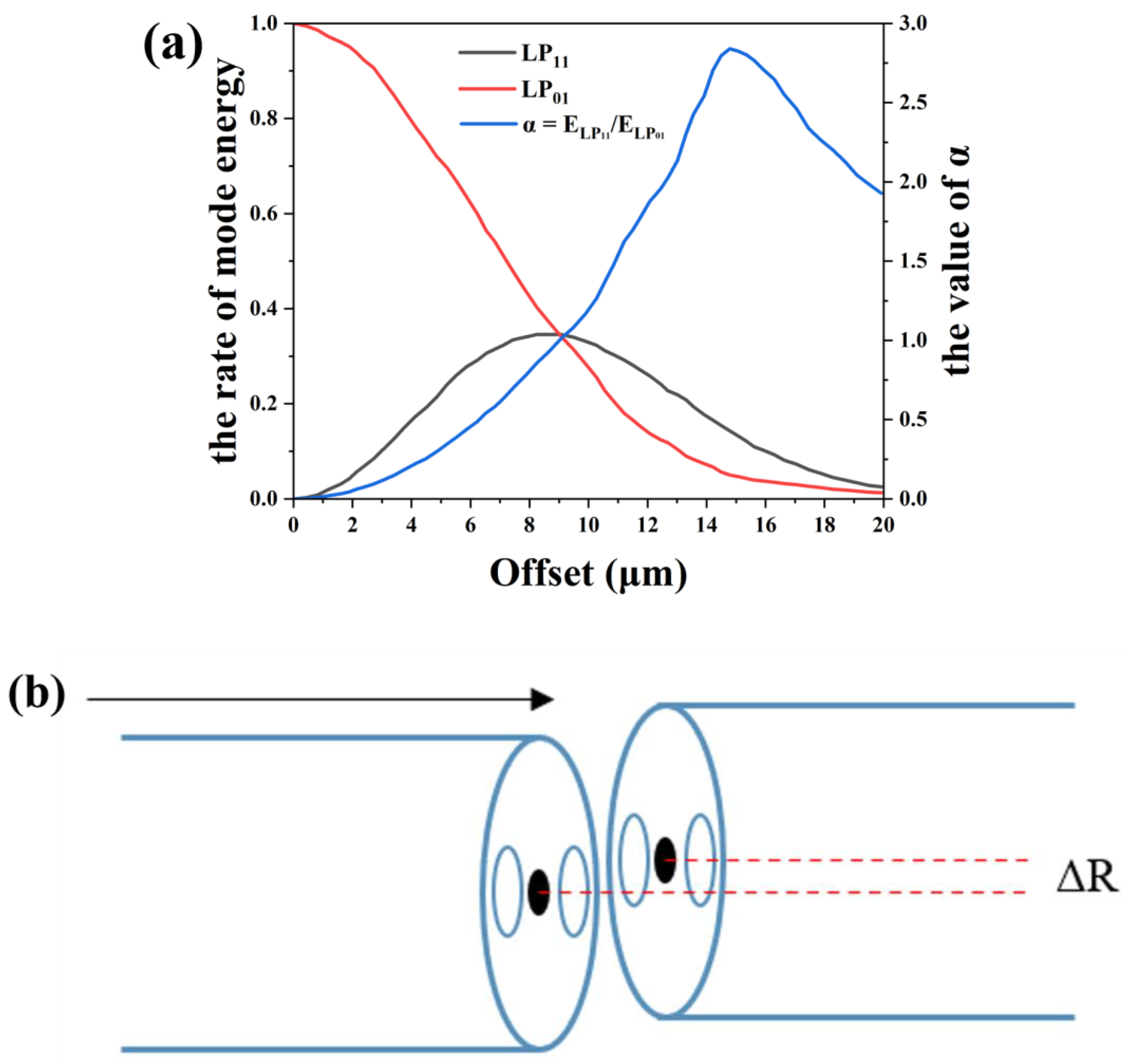
The so-called offset splice point (OSS), as shown in
Figure 3b, is designed to excite the second-order transverse modes in few-mode fibers. The coupling efficiency of the inherent modes at both ends of the waveguide depends on the mode field distributions and overlap area of both the exciting light and the excited light. This can be expressed using the following formula [
20]:
In this context,
represents the normalized mode distribution within the fiber, while
indicates the mode field distribution of the exciting light at the receiving fiber’s end face. When the waveguide structures of the exciting and excited light are consistent, the light field distribution in the excited light’s waveguide completely integrates with that of the exciting light, resembling the stable transmission of guided modes in a complete fiber waveguide. To excite higher-order mode fields, it is essential to break the consistency and symmetry between the two. The primary implementation method involves offset incidence excitation. The direction of offset can be either perpendicular to the direction of the boron rod or along the direction of the boron rod, which is referred to as the direction perpendicular to the boron rod in this article. To determine the optimal offset distance for effectively exciting the LP
11 mode, the relationship between the mode ratio and offset distance was calculated using the Beam Propagation Method (BPM), as shown in
Figure 3a. The ratio is introduced as
, where
and
represent the intensities of the LP
11 and LP
01 modes in the two-mode fiber (TMF), respectively. When the ratio
reaches its maximum, an optimal offset distance exists. The calculations indicate that the best offset distance is 14.8 µm, at which point
achieves a maximum value of 2.84. In the actual operation process, set the fiber fusion splicer to fusion mode, input the information of the two ends of the fiber, and then change the axis alignment method to manual and adjust it to 14.8 µm. Finally, set the discharge power to 519 bit and the discharge time to 6000 ms. Furthermore, the combined intensity of the LP
11 and LP
01 modes is only 0.192 times the initial strength, which is a significant reason for the comparatively low output power slope efficiency.
3. Results and Discussion
The output characteristics were measured and recorded. As shown in
Figure 4, at a pump power of 20.9 W, the maximum output power reached 3.8 W, with a slope efficiency of approximately 18.4%. The main reason for low efficiency is the significant loss at the offset splicing point, and a small part of the reason is the loss of fiber fusion splicing point. By reducing the splicing loss of different fibers, further optimization can be achieved. The output beam profile at maximum output power is illustrated in the inset of
Figure 4a. The beam profile was monitored using a CCD camera, and a typical LP
11 mode with two lobes was obtained at maximum output power, with its mode purity measured using the fiber bending method [
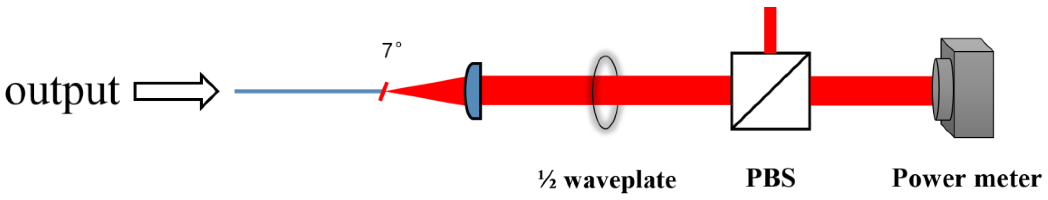
5], yielding a value of approximately 95.32%. To measure the polarization extinction ratio (PER) of the output beam, a half-wave plate and a polarization beam splitter (PBS), as shown in
Figure 5, were employed as linear polarizers. When the angle between the optical axis of the half-wave plate and the polarization direction is
, the polarization direction of the output light rotates by 2
. When it is consistent with the P-polarization direction of PBS, the maximum transmitted light intensity is denoted as
, and when it is consistent with the S-polarization direction of PBS, the minimum transmitted light intensity is denoted as
. Calculate PER using the formula
. The PER of the output beam at different output powers is presented in
Figure 4b. At the highest output power, the polarization extinction ratio (PER) was found to be as high as 96.7%. It is worth noting that compared to the no-polarization-maintaining fibers used in other studies [
5], this study verified the possibility of generating a linearly polarized LP
11 mode through a polarization-maintaining fiber system using a fully polarization-maintaining fiber system, and achieved watt-level output and high PER results, providing a strong foundation for subsequent power amplification.
To confirm the stability of the single-polarization LP
11 mode output laser, we conducted a stability test over a period of 120 min in an environment with a temperature of 23 degrees Celsius and a relative humidity of around 50%, recording the output power using a power meter and the polarization extinction ratio (PER) using a half-wave plate and a polarization beam splitter (PBS) every minute. The relationship between output power, PER, and time is illustrated in
Figure 6. The standard deviation for the output power was 0.15%, while the standard deviation for the PER was 0.06%, indicating that the laser exhibits excellent stability. For clarity, the slow-axis direction of the PMFMFBG is defined as the x-polarization direction, while the fast-axis direction is designated as the y-polarization direction. The output power diagrams for both x-polarization and y-polarization are illustrated in
Figure 7. We observed that the PER did not reach a particularly high value. Upon analysis, this is attributed to the presence of four fusion splice points between polarization-maintaining fibers within the laser system, including one offset splicing point and one splice point between polarization-maintaining fibers of different specifications. The fusion splice errors introduced by these four points contribute to the reduction in the PER of the output laser.
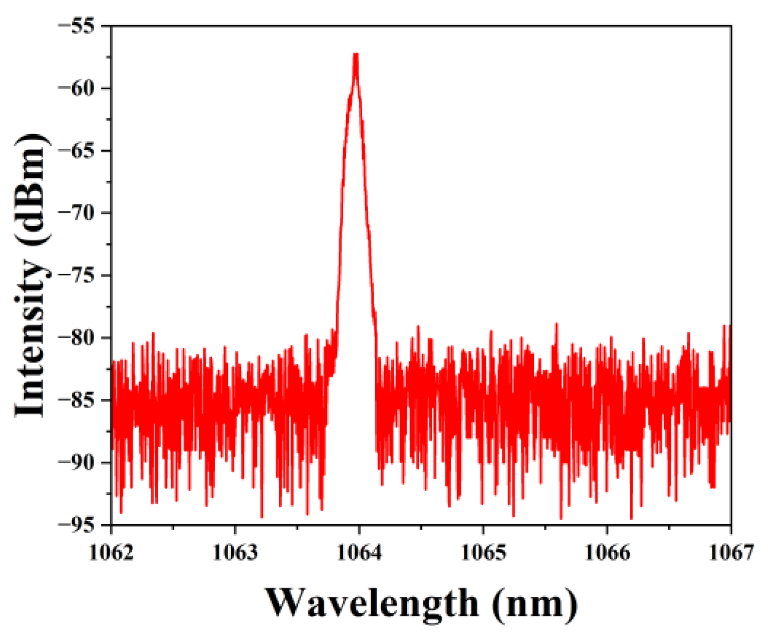
Finally, spectral measurements were conducted using a spectrometer. At the maximum output power of 3.8 W, as shown in
Figure 8, the center wavelength at full-width half maximum (FWHM) was measured to be 1063.96 nm with a spectral bandwidth of 0.32 nm. Furthermore, the spectral data indicated that any remaining pump light was completely filtered out by the CPS.


