2.1. Mirror Support Scheme
Mirror support structures can be categorized based on the location of contact points into peripheral, side, central, and back supports [
16]. Peripheral support is often used for small-sized mirrors, using the surface or edge of the lens as a reference, and the lens is secured to the frame or seat using a pressure ring for system positioning. Side support uses the side edge of the mirror as a reference for positioning, connecting the mirror to the system via screw fastening or adhesive bonding, which is a relatively common method of fixing mirrors. Central support is widely used in medium and small-aperture mirrors, often employed in optical systems with a central hole, and is a support method that uses the central position of the mirror as a reference for positioning. The support structure is fixed to the central hole of the mirror through adhesive bonding, offering advantages such as small structural size, simple structure, and ease of design. Back support is commonly used in medium-to-large-aperture mirrors, positioning and supporting the mirror through blind holes on the back of the mirror connected to a cone sleeve and flexible joint. The most classic of these support methods is the three-point back support, which, based on the principle of three-point positioning, can be evolved into six-point, nine-point, eighteen-point, and twenty-seven-point support configurations [
17].
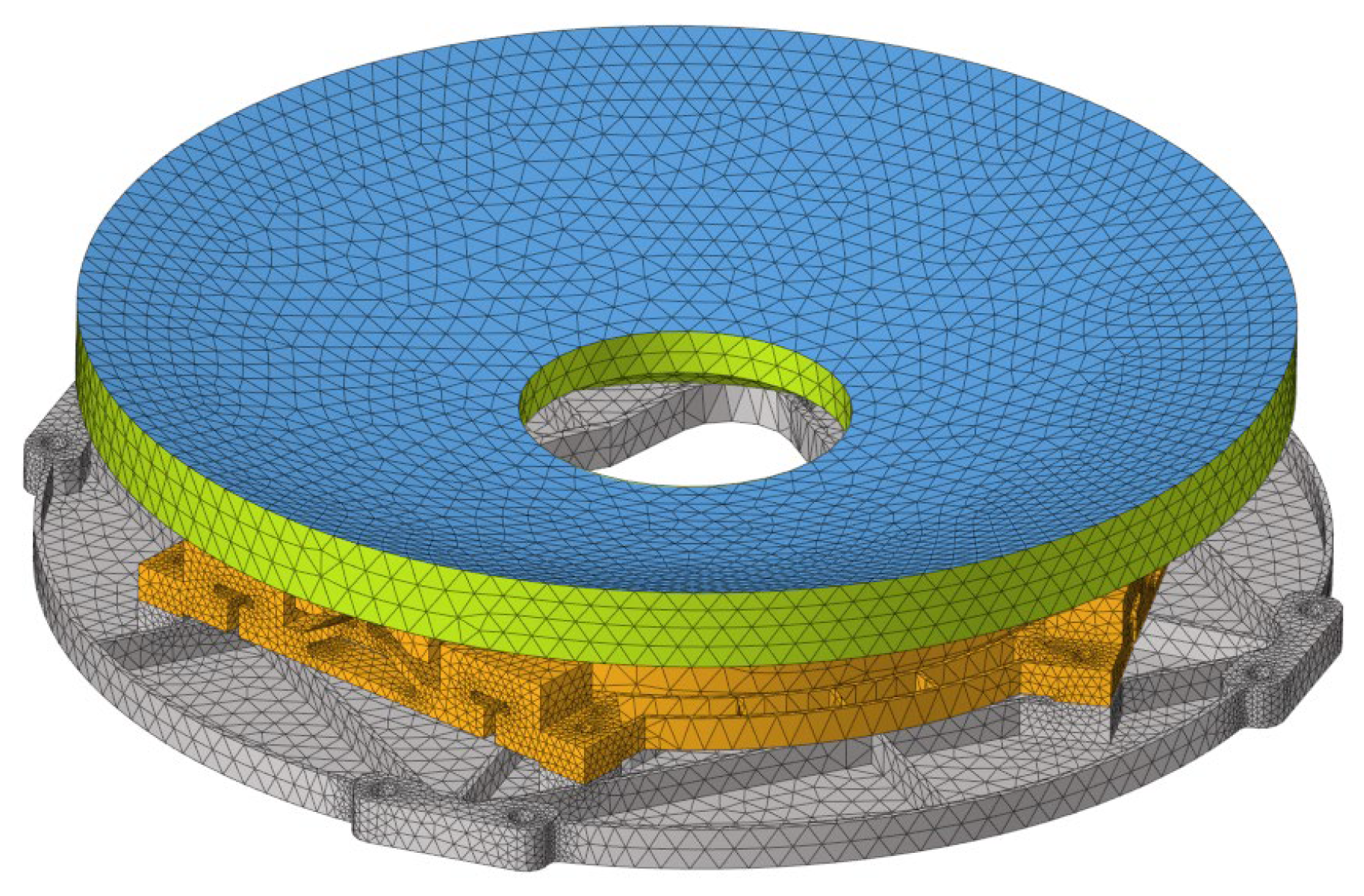
This system is a pre-research device, and there is a potential need for mass production in the future. Therefore, manufacturability and the time and economic costs are important considerations. In the selection of the mirror support scheme, central support is less complex in terms of assembly and adjustment compared to side and back support, and it does not introduce over-constraint, making it easier to achieve assembly. The mirror has a diameter of 240 mm, classifying it as a medium-to-small-aperture mirror, and it features a central control structure. To meet the rigid body displacement requirements of the component, and considering manufacturability, cost, and assembly complexity, central support was ultimately chosen as the support scheme for the mirror. The mirror assembly consists of three parts: the mirror, the flexible flange, and the backplate. The circular “tail” at the back of the mirror is adhesively bonded to the inner ring of the flexible flange, which is then connected to the backplate via bolts. Finally, the backplate is connected to the main optical system using four sets of installation surfaces with bolts, as shown in
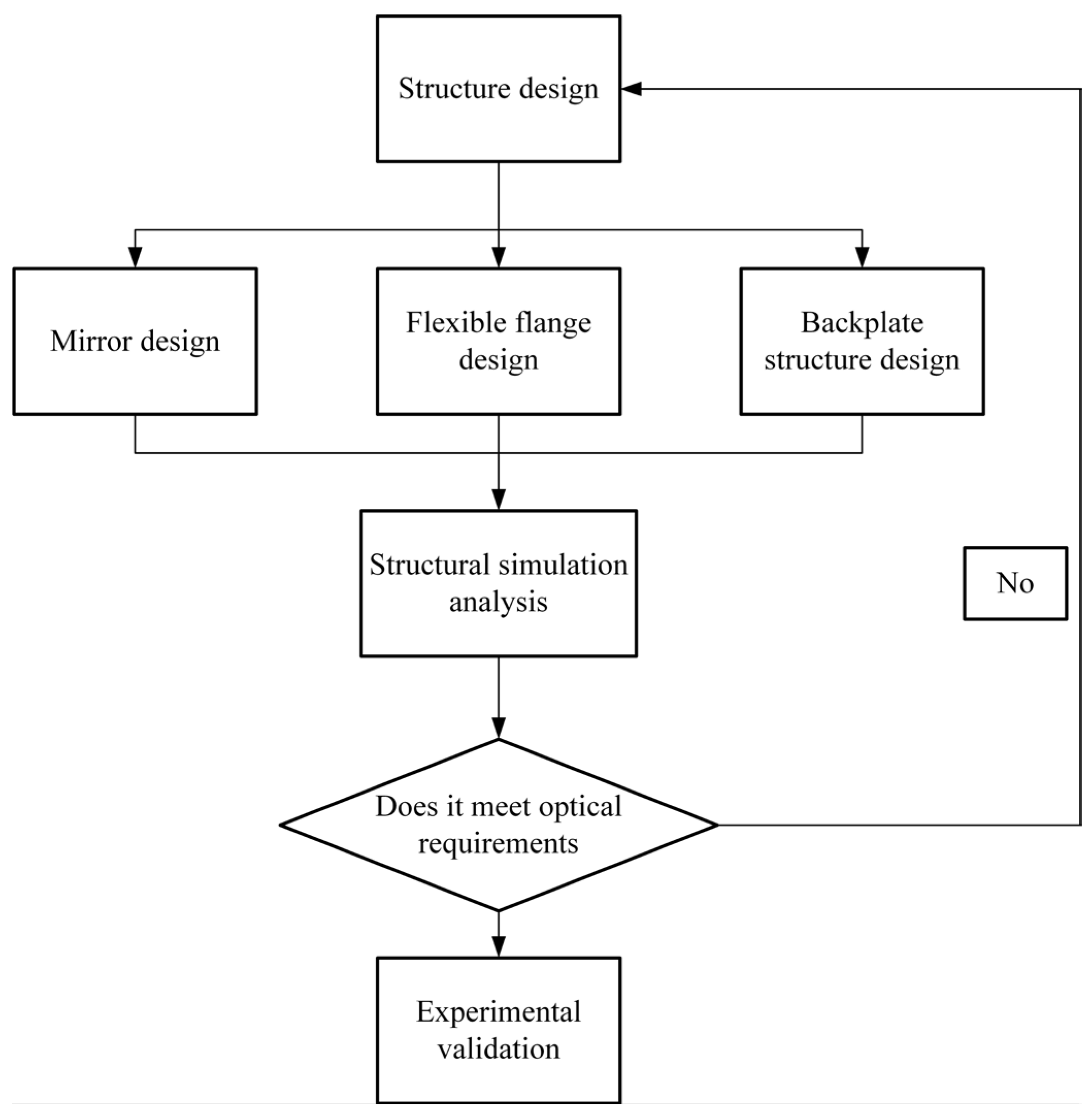
Figure 1. The design process is primarily divided into three parts, as illustrated in
Figure 2: structural design of the assembly, finite element simulation analysis, and experimental validation.
2.2. Mirror Design
Mirrors, composed of a rigid body, place greater emphasis on their physical properties to ensure the spatial position of the reflective surface and the surface figure of the mirror. Therefore, the selection of mirror materials requires consideration of the mechanical properties and thermal stability of the mirror blank, as well as good machinability.
The commonly used mirror materials and their characteristics are shown in
Table 2, it can be observed that SiC material has a higher elastic modulus and stiffness compared to ULE, Zerodur, and Al, offering advantages such as high thermal conductivity, high specific stiffness, and excellent thermal stability. However, it also has significant drawbacks, including high material hardness, difficulty in processing, high cost, and long processing cycles. Al, as a commonly used structural material, has a larger coefficient of thermal expansion and a lower stiffness compared to other materials, making it suitable for optical systems with minimal environmental temperature changes and lower precision requirements. ULE can be applied to closed-back structures, which significantly increases the stiffness of the mirror compared to Zerodur, leading to a greater lightweighting ratio, but its production cost is high and the processing cycle is long, typically used for large-aperture space mirrors. The ϕ 240 mm aperture mirror in this project is categorized as a medium-to-small aperture. Although ULE exhibits similar performance to Zerodur, its manufacturability is inferior to that of Zerodur, resulting in longer processing times and higher costs. Considering the manufacturability, time and economic costs, as well as the potential for future mass production, ULE is not suitable as the material for the mirror. Zerodur is readily available, has relatively low cost, mature technology, and a shorter surface figure polishing cycle, making it particularly suitable for mass production when it meets usage requirements. After a comprehensive comparison of the aforementioned materials, Zerodur is chosen as the mirror material.
Compared to solid structure mirrors, porous sandwich structures are a more efficient form and are commonly used as lightweight structural types. By removing materials that contribute little to the overall stiffness of the structure, the specific stiffness of the structure is increased, and the structural form becomes more rational. However, this form of lightweighting has a longer processing cycle, higher processing costs, and is highly prone to mechanical processing residual stresses [
18]. Therefore, in this paper, lightweighting is only achieved by slightly altering the contour of the mirror’s back substrate. Due to the use of central support, the mirror substrate is shaped into a single-arch form. In single-arch mirrors, the center of gravity is located near or in front of the top point of the mirror surface, making the surface figure of the single-arch mirror susceptible to the influence of gravity. Adjusting the center of gravity below the reflective surface can reduce this impact.
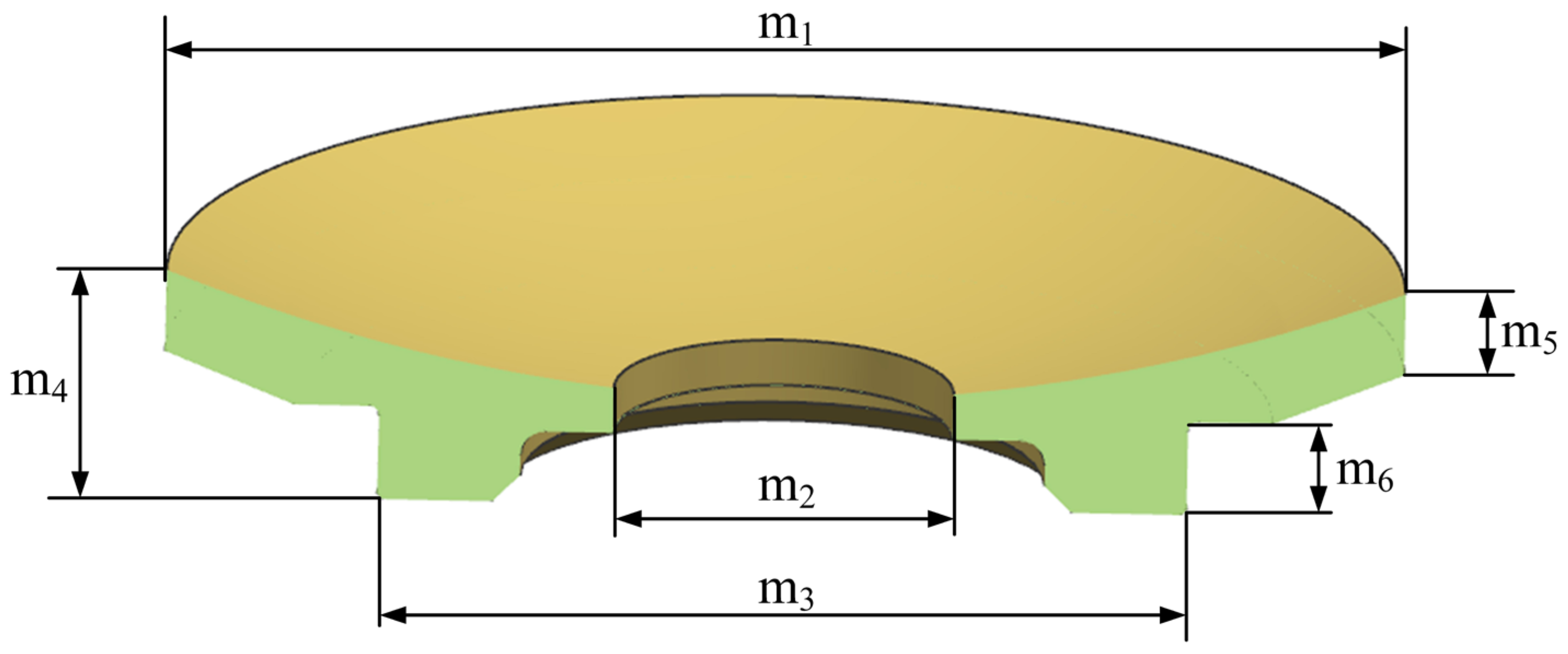
Thus, unlike the traditional single-arch mirror structure, this design includes a “tail” at the bottom of the mirror with a thickness of t. This design serves two purposes: on one hand, to adjust the center of gravity of the mirror so that it is as much as possible below the reflective surface, reducing the impact of gravity on the surface figure accuracy; on the other hand, to meet the needs of the mirror’s adhesive area. The mirror’s design takes into account factors such as the support structure form, lightweighting, and mirror surface processing technology. Through engineering analysis and optimization of the mirror’s diameter, body thickness, and single-arch shape dimensions, the actual shape of the mirror is designed as shown in
Figure 3. The diameter of the main mirror is ϕ 240 mm, the diameter of the central hole is ϕ 68 mm, the thickness of the mirror m
4 = 50 mm, the thickness of the edge of the mirror m
5 = 17 mm, the thickness of the cementation m
6 = 19.5 mm, and the radius of the cementation m
3 = 162 mm. The circumference of the “tail” on the back of the mirror is the bonding surface with the support structure.
2.3. Flexible Flange Design
The complex thermal environment within aerial pods leads to significant temperature variations, causing thermal elastic deformation of the camera, which, in turn, leads to deviations in the optical surface figure of mirrors and changes in spacing, degrading the imaging quality of the optical system. Additionally, during ground assembly and testing, the influence of gravity orientation changes and assembly stresses resulting from manufacturing errors also affect the imaging quality of the system. Therefore, to meet the specifications for surface figure and rigid body displacement of the mirror under force and thermal environments, a support form combining inner and outer rings with circular arc-shaped flexible hinges is proposed. This design reduces the strain energy of the mirror body through its own deformation, thereby reducing the surface figure error of the mirror. While ensuring the rigidity and strength requirements of the component itself and the overall camera, increasing the flexibility of the flexible flange eliminates the stresses produced by temperature changes and gravity orientation changes, and also eliminates the impact of assembly stresses.
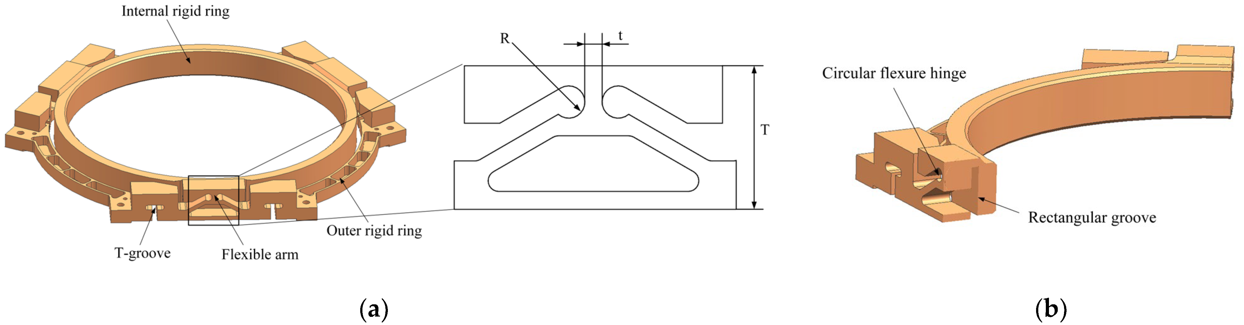
To meet the system’s wide temperature range usage conditions of −40 °C to 50 °C and compensate for thermal stress, the linear thermal expansion coefficient of the flexible support structure material must be matched with the microcrystalline material used for processing the mirror, as mentioned earlier. Although 4J32 Invar steel has a lower specific stiffness, its thermal expansion coefficient is closest to that of microcrystalline glass material, making it the material of choice for the flexible support structure. As shown in
Figure 4, the structure mainly consists of an internal rigid ring, an outer rigid ring, and flexible arms; the total thickness is 21 mm. The internal rigid ring is in the form of a ring structure, with its inner wall adhesively bonded to the circular “tail” on the back of the mirror body, and the diameter of the inner ring is ϕ 162, which matches the size of the main mirror; the outer rigid ring extends three sets of evenly distributed mechanical interfaces outward from the ring structure to connect with the backplate, with T-shaped grooves at the mechanical interface parts, which can appropriately increase the radial flexibility of the support structure. Through its own elastic deformation, it absorbs external loads and releases installation stresses. The structure adopts a lightweight design, with a number of reinforcing ribs left in the circumferential direction of the ring and the rest of the parts removed. A rectangular groove is made between the internal and outer rigid rings to avoid rigid connection between the internal and outer rings, and connected by three evenly distributed flexible arms in a circular manner. Since the circular arc-shaped flexible hinge has higher rotation precision compared to the straight beam-type, circular arc-type, and elliptical flexible hinges, the center of rotation does not shift significantly during rotation. This design reduces the floating of the hinge center, thus providing good comprehensive performance. Therefore, the circular arc-shaped flexible hinge is used as the structural form of the flexible arm, effectively reducing the impact of the uneven installation surface of the mirror assembly on the mirror surface figure. As shown in the figure, the slot radius of the flexible arm R = 2.25 mm, the thinnest thickness t = 3.4 mm, and the hinge thickness b = 10 mm; these are explained in detail in the following article.
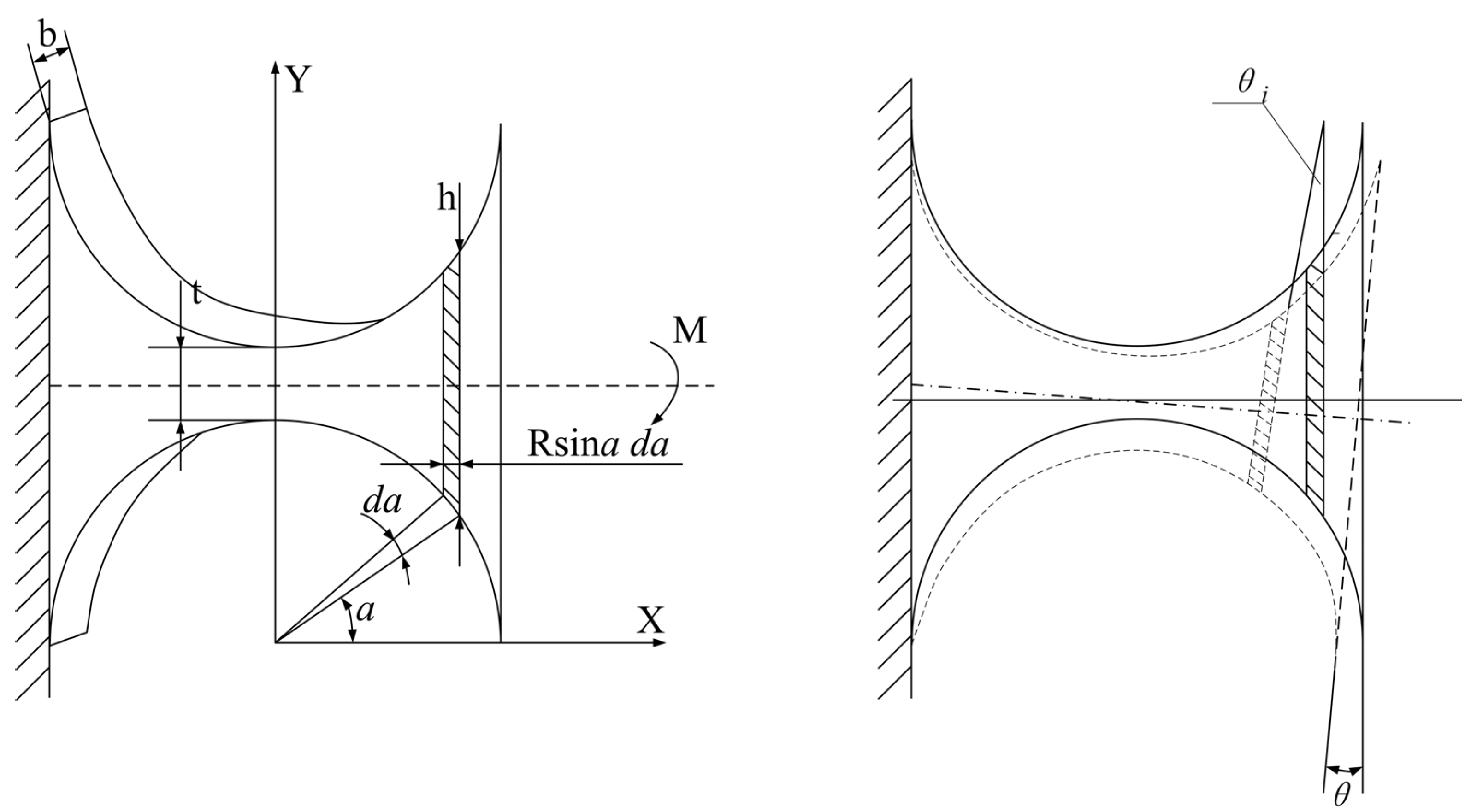
Figure 5 illustrates the schematic diagram of an arc-shaped flexible hinge, with geometric dimension parameters including the central angle, the cutting circle radius
R, width
b, height
h, and minimum thickness
t, among others. The calculation method for the rotational stiffness of the hinge under the action of a bending moment
M is analyzed. The formula for the rotation angle of the flexible hinge in the support structure, after simplification, is as follows:
Consider a point (
x,
y) on the flexible joint, which undergoes angular displacement under the action of the moment
M. Since the angular displacement is small, it can be considered
and is expressed by the following formula [
19]:
According to the theory of mechanics of materials, the curvature at an infinitesimal element
dx of the structure is given by:
In the equation mentioned above, represents the curvature at the infinitesimal element dx after deformation, E is the elastic modulus of the material for the arc-shaped flexible hinge structure, M is the bending moment at the infinitesimal element dx after deformation, and J(x) is the moment of inertia at the infinitesimal element dx.
According to the curvature formula, the curvature at any point on the curve
y =
f(
x) can be calculated using the following formula:
Given that the angular displacement of the flexible hinge is very small, the square terms can be neglected, thus simplifying Equation (4) to:
Combining Equations (1) and (5), we obtain:
Given that the primary focus of stiffness analysis is the functional relationship between structural parameters and stiffness, the constants in Equation (6) can be disregarded. Transforming the Cartesian coordinates in Equation (6) into polar coordinates, we have the following relationships:
Considering the central angle of the arc-shaped flexible hinge to be 180°, and integrating within the interval [0, π], the rotational angle formula for the support structure’s flexible hinge is given by:
The rotational angle
θ of the flexible hinge is determined using the method of integration, and the rotational stiffness under the action of the bending moment
M is derived as:
In the equation, b is the width of the hinge; R is the radius of the arc of the flexible hinge; and t is the minimum thickness of the flexible hinge. Using the above formula, the stiffness value K of the arc-shaped hinge can be calculated for different dimensional parameters, thereby designing an arc-shaped flexible support structure that meets the requirements.
By analyzing the impact of different dimensions of
R,
t, and
b on the rotational stiffness
K of the flexible hinge through the aforementioned formula, the variation curves of the rotational stiffness with respect to the hinge structural parameters are obtained as shown in
Figure 6 and
Figure 7. It can be observed from the figures that the hinge width
b has a linear relationship with the rotational stiffness, while the minimum thickness
t of the flexible hinge significantly affects the rotational stiffness
K. As
t increases, the rotational stiffness increases in a quadratic manner. The influence of the radius
R on stiffness becomes more pronounced; conversely, as
R increases, the rotational stiffness decreases, indicating that the impact of
R on the flexibility of the hinge is minimal. Concurrently, the rotational stiffness of the flexible flange exhibits a monotonically increasing relationship with the hinge parameters. However, as the parameters increase, the system stiffness becomes greater, rendering the system more rigid. This results in reduced buffering capacity and a corresponding decrease in flexibility. Consequently, the system’s surface deformation tends to deteriorate under the influence of mechanical and thermal loads. Nevertheless, this relationship is difficult to fully describe using a mathematical expression. Therefore, we selected an appropriate dimension and obtained satisfactory results through finite element analysis. Therefore, in the actual design process, the values of
R and
b should be determined based on the structural requirements, followed by the determination of the minimum thickness
t to ensure the rotational stiffness of the flexible hinge. Integrating the aforementioned design theory, this paper proposes a flexible support structure suitable for medium and small-sized mirrors, taking into account the requirements for axial stiffness and radial flexibility, as well as structural design constraints. Ultimately, the following dimensions were determined: slotting radius
R = 2.25 mm, minimum thickness
t = 3.4 mm, and hinge thickness
b = 10 mm.


