Article

Continuous-Wave Room-Temperature External Cavity Quantum Cascade Lasers Operating at λ~8.5 μm

1
Laboratory of Solid State Optoelectronics Information Technology, Institute of Semiconductors, Chinese Academy of Sciences, Beijing 100083, China
2
Center of Electronic, Electrical and Communication Engineering, University of Chinese Academy of Sciences, Beijing 100049, China
3
Weifang Academy of Advanced Opto-Electronic Circuits, Weifang 261021, China
*
Author to whom correspondence should be addressed.
Photonics 2025, 12(2), 129; https://doi.org/10.3390/photonics12020129
Submission received: 12 January 2025 / Revised: 29 January 2025 / Accepted: 29 January 2025 / Published: 31 January 2025
(This article belongs to the Special Issue The Three-Decade Journey of Quantum Cascade Lasers)

Abstract

:
External cavity quantum cascade lasers (EC-QCLs) utilizing the Littrow configuration and operating at an approximate wavelength of 8.5 μm have been successfully demonstrated in continuous wave operations at room temperature. Our work provides ideas and experimental support for the optimization of the EC-QCL which indicate optimal EC-QCL performance with an external cavity length of 25 cm and investigates the impact of various parameters, including injection current and temperature on the performance of the EC-QCL. In the absence of anti-reflection (AR) coating, the tuning range at 25 °C extends up to 103.3 cm−1, while the maximum side mode suppression ratio (SMSR) reaches 30.8 dB, accompanied by a full width half maximum linewidth (FWHM) of 0.76 nm.

1. Introduction

Quantum cascade lasers (QCLs) serve as the prominent mid-infrared laser sources, which are widely employed in gas trace detection applications, such as emission measurement, environmental monitoring, medicine, and security [1,2,3]. Typically, widely tunable mid-infrared light sources with narrow linewidths are needed for detecting of high sensitivity and precision. The external cavity quantum cascade laser (EC-QCL) configured in Littrow geometry presents a feasible solution [4,5]. For instance, Arun Mohan et al. developed a continuous-wave (CW) operation Littrow EC-QCL operating at 8.7 μm, demonstrating a wavelength tuning range of 120.0 cm−1 and a peak power of 20.0 mW [6]. S. Hugger et al. achieved EC-QCLs at a wavelength of 8.5 μm, in which EC-QCLs used the Littrow structure. The use of MEMS rotating mirrors improved the compactness and output performance to a certain extent, with a tuning range of up to 330 cm−1 and a maximum output power of 45 mW [7]. Moreover, S. Tan et al. presented the EC-QCL with a tuning range of 116.0 cm−1 around 4.7 μm under CW conditions, achieving the side mode suppression ratio (SMSR) exceeding 30 dB near the central region through meticulous external cavity length design [8].
In order to improve the output performance of the EC-QCL, the most commonly used method is applying anti-reflection (AR) coatings to mitigate cavity effects [9,10,11]. However, materials for high-performance AR coatings in the long wavelength range are still limited, compared to those in the short wavelength case [12]. Therefore, some researchers attempted to improve the output performance of the EC-QCL from other aspects without AR coatings. As stated in Ref. [8], S. Tan et al. have conducted preliminary optimization on the external cavity length through a simulation around 4.7 μm. However, the impact of the external cavity length on the output performance of the EC-QCL has not been fully explored. In this work, both the simulations and experimental explorations were conducted on the external cavity length of the EC-QCL, demonstrating that the EC-QCL can possess the best output performance with an external cavity length of 25 cm. Simultaneously, the injection current of the EC-QCL was also optimized, which proves that the tuning range is maximized when the injection current is the threshold current of the Fabry–Perot (FP) mode. In addition, the influence of temperature on threshold current and output power was explored. Our work provides ideas and experimental support for the optimization of the EC-QCL.
In this study, the CW mode operated-external cavity quantum cascade laser at a wavelength around 8.5 μm under room temperature is reported, achieving a tuning range of 103.3 cm−1 at 25 °C, a maximum SMSR of 30.80 dB, and a full width half maximum (FWHM) of 0.76 nm by comprehensively optimizing the external cavity length, injection current, and operating temperature.

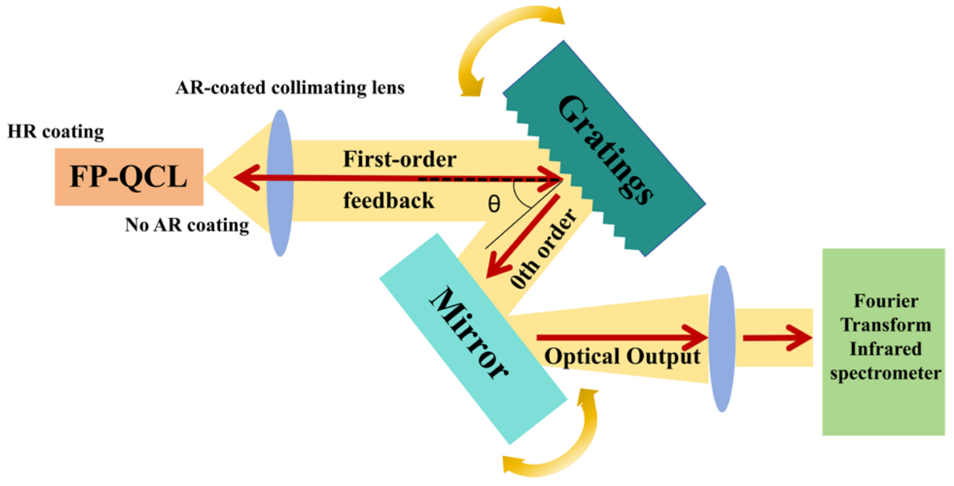
2. External Cavity Setup

The QCL wafer with 35 cascade stages, based on single-phonon continuum depopulation, was adopted for the EC-QCL study. QCLs featuring an active region width of 9.5 µm were manufactured using standard photolithography and wet etching techniques by our laboratory. After that, the buried heterojunction process was used for electrical isolation and to form thermal pathways, which is conducive to effectively regulate the temperature of the active region and reduce sidewall losses. Ti-Au metallization was used for top and back contacts. The processed QCL wafer was cleaved into chips with a cavity length of 3 mm for HR facet coating, which consisted of Y2O3/Ti/Au/Y2O3 and the front surface is not coated with AR coatings. Then, the devices were mounted epi-side down on a diamond substrate for testing. In the experimental setup, a grating with 150 grooves/mm and a diffraction angle of 39.0° at 8.5 µm (as illustrated in Figure 1) was utilized in a Littrow configuration for the EC-QCL. The grating’s blazed efficiency can achieve up to 90%. The first-order diffracted light, generated by the grating, inducing external cavity oscillation in the QCL, while the zeroth-order diffracted light served to produce a tunable single-mode laser.
In the experiment, an optical collimator which was manufactured by Thorlabs in Newton, NJ, USA, with a focal length of 1.87 mm and a numerical aperture of 0.85, was utilized to collimate the light beam. After collimation, the beam directly passed through a blazed grating, reflected by the output mirror, and finally was collected in the Fourier Transform Infrared spectrometer (FTIR, which was manufactured by Thermo Fisher Scientific in Waltham, Massachusetts, USA) for spectral acquisition, as shown in Figure 1. The blazed grating rotated along the slow axis direction to ensure relative accuracy of the linewidth. A high resolution was employed to ensure that the data points for a single-mode spectrum exceeded 15. The apodization parameter was set to “Nuttall-Blackman apodization function” [13] to minimize peak side lobes, caused by the limited distance of the Michelson interferometer moving mirror. The output power was measured by a Thorlabs PM100D power meter with S405C thermopile detector which has an active detector area for effective collection. The output diffracted zeroth-order light passed through the second focusing mirror and was collected and measured by the power meter.

3. Result and Analysis

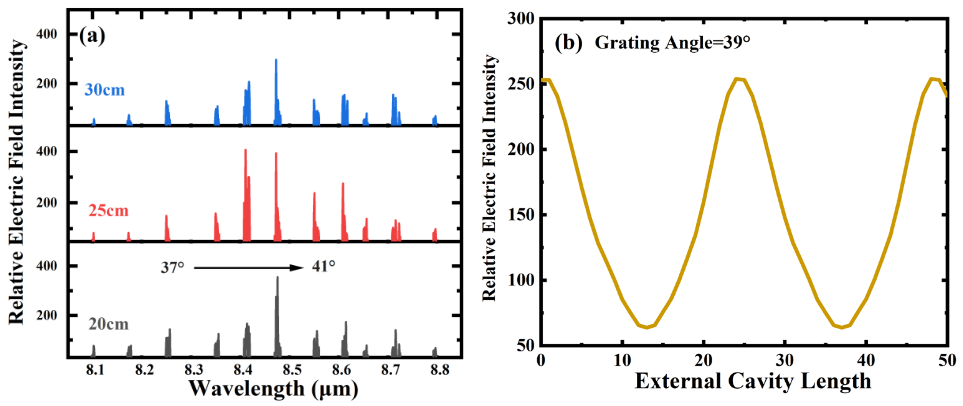
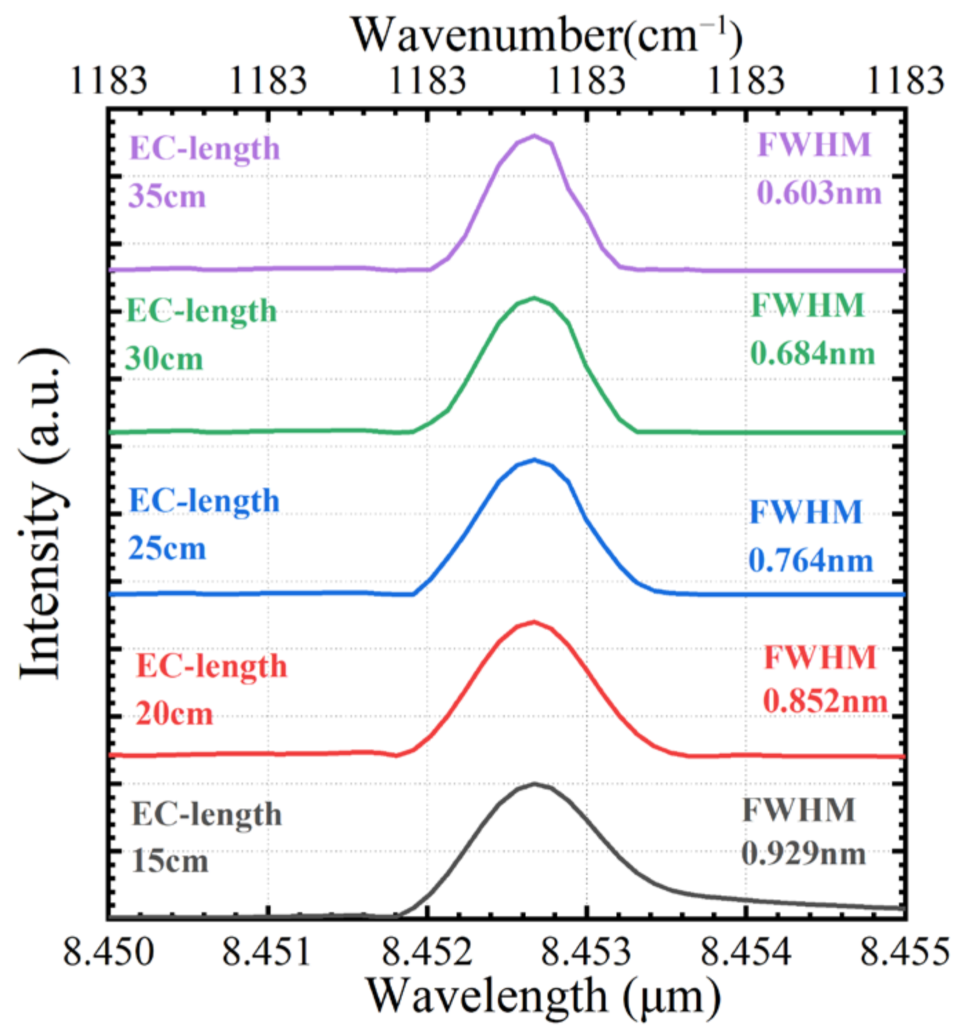
3.1. Effect of External Cavity Length

The EC-QCL can be analyzed as a coupled system of two resonant cavities, which is more conducive to explaining related phenomena. The two cavities are the chip cavity, which is formed by the front and rear cavity surfaces of the QCL, and the external cavity, which comprises the HR surface of the QCL’s rear cavity and the diffraction grating [14]. Based on this model, the relative electric field strength of the entire system can be calculated according to the propagation path of light waves in this coupled cavity system, and the relevant parameters can be expressed as follows [1],
I I 0 = E × E E 0 × E 0 = ( 1 R 2 R 3 e j φ 23 1 R 2 R 3 e j φ 23 G L R 1 R 2 e j φ 12 G L R 1 R 3 ( 1 2 R 2 ) e j φ 13 ) 2
φ = 4 π l λ
In Equations (1) and (2), E is the electric field of the QCL FP resonator; λ represents the laser excitation wavelength. R1 is the reflectivity of the QCL back cavity surface, which is assumed to be 98%; R2 is the reflectivity of the QCL front cavity surface, which is approximately 27%; and R3 is the grating reflection efficiency, which can be calculated based on the intensity before and after reflection. φ12, φ13, φ23 represent the phase shift generated by the laser in a reciprocating mirror. l12 refers to the distance between the front and rear cavity surfaces of the QCL, corresponding to a phase shift of φ12; l13 is the distance between the QCL back cavity surface and the diffraction grating, corresponding to a phase shift of φ13; l23 is the distance between the QCL front cavity surface and the diffraction grating, corresponding to a phase shift of φ23; G and L represent the gain and loss of the gain chip, respectively.
The QCL gain chips can be considered homogeneous media due to their rapid relaxation processes. In the absence of any mode-selection structure, either internal or external, the spatial electric field distribution of the mode’s standing wave only weakly overlaps with the main longitudinal mode. In this case, spatial hole burning generates a multi-mode phenomenon. However, when an external mode-selection element is introduced, only modes that satisfy the phase conditions of the diffraction grating reflection spectrum will lase, resulting in single-mode operation. As indicated by Equations (1) and (2), changing the length of the external cavity alters its phase, which in turn modifies the excitation wavelength and intensity that meet the phase condition. Figure 2a shows the numerical simulation of the tuning behavior of the EC-QCL system as the grating angle is varied for different external cavity lengths. Figure 2b depicts the variation in relative electric field intensity from 0 to 50 cm as the external cavity length changes at the grating angle of 39.0°. It is noteworthy that the grating angle of 39° may not correspond precisely to the maximum relative electric field intensity as shown in Figure 2a, which results in the highest electric field intensity of only around 250 in Figure 2b.
As can be seen from Figure 2b, the relative electric field strength exhibits periodic variations with changes in the external cavity length. Additionally, 15–35 cm is approximately one cycle, and the maximum value appears at 25 cm. Therefore, we set the external cavity length within the range of 15 cm to 35 cm and conducted tests on the L-I-V curves for these lengths to explore the impact of relative electric field strength on the output performance of the L-I-V curve.
Figure 3 illustrates these L-I-V curves for varying cavity lengths, tested at a diffraction angle of 39.0° and a temperature of 25 °C. It shows that the threshold current reaches its lowest value which is 626.5 mA when the external cavity length is 25 cm. When the cavity length is 20 cm, the threshold current is 662.4 mA, and it rises slightly to 666.4 mA when the length extends to 30 cm. This represents an overall reduction of approximately 6.4% in the threshold current of the EC-QCL when the cavity length is optimized. Additionally, it is noteworthy that the threshold current of the Fabry–Perot-Quantum cascade lasers (FP-QCL) with HR coating was 735.6 mA. In contrast, the EC-QCL’s threshold current significantly decreased to 626.5 mA at an external cavity length of 25 cm. This reduction may be attributed to the introduction of external gratings in the EC-QCL which effectively lower mirror loss. After introducing an external grating into the EC-QCL, considering the multiple back and forth movements of the laser inside the cavity when calculating the threshold conditions of the EC-QCL, the concept of effective reflection coefficient is introduced. The external cavity part between the front cavity surface of the gain chip and external grating is equivalent to a reflection plane, where the reflectivity of the reflection plane increases compared to the reflectivity of the front cavity surface of the FP-QCL, which effectively reduces the mirror loss. As a result, the threshold current of the EC-QCL is lower than that of the FP-QCL [15,16]. Another important observation is that the EC-QCL produces significantly less power compared to the FP-QCL; the maximum output power of the FP-QCL was 248 mW, while that of the EC-QCL was only 114 mW. This drop in output power can be attributed to the fact that the primary source of light from the EC-QCL is zeroth-order light diffracted by the grating, which has a lower diffraction efficiency. However, it should be noted that the output power of the EC-QCL surpasses that of other groups (45 mW in Ref. [7] and 50 mW in Ref. [11]) under identical conditions. This may be partly attributed to optimizing the cavity length based on the relative electric field intensity, which reduces the threshold current while increasing the output power.
The EC-QCL is realized through the integration of an external resonant cavity, effectively increasing the overall length of the resonant cavity. This elongation is advantageous as it augments stimulated radiation while concurrently diminishing spontaneous radiation, leading to a reduction in the output laser linewidth. Meanwhile, the use of diffraction gratings, essentially functioning as bandpass filters, can also contribute to linewidth narrowing. This can be approximated by evaluating the grating’s resolution. As illustrated in Figure 4, the EC-QCLs were examined at a constant diffraction angle of 39.0° and a temperature of 25 °C, with external cavity lengths set at 15 cm, 20 cm, 25 cm, 30 cm, and 35 cm, respectively. It is evident that an increase in resonant cavity length corresponds to a decrease in linewidth. However, the threshold current and output power performance are better at the external cavity length of 25 cm. In addition, the feedback loss increases with the increase in the external cavity length. Affected by these factors, 25 cm was set as the external cavity length in the subsequent experiments; the corresponding linewidth was 0.76 nm.

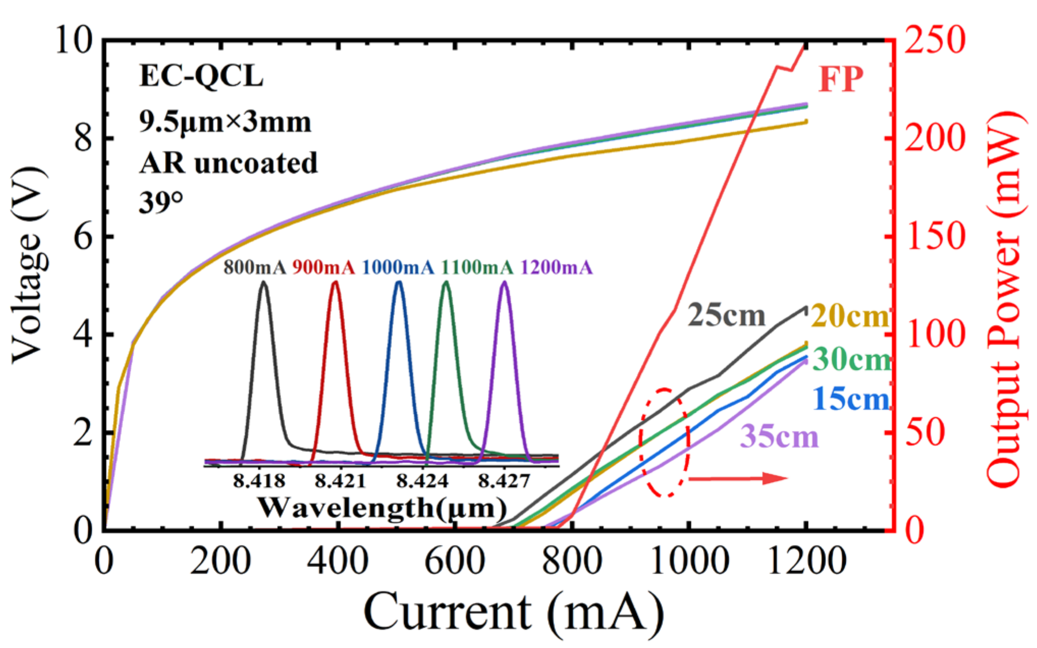
3.2. Effect of Injection Current

Figure 5 depicts the wavelength tuning curve at various grating angles in the CW mode at 25 °C with a 25 cm external cavity length. The injection current is 730 mA, and the grating rotation angle varies from 37.0° to 41.0°. The figure shows a linear relationship between different grating angles and lasing wavelength, with a linear tuning coefficient of 181.3 nm/deg and a tuning range from 1237.7 cm−1 to 1136.3 cm−1. As the diffraction angle deviates from the shining angle, the SMSR will gradually decrease. At the center wavelength around 8.5 μm, the SMSR reaches a peak of 30.80 dB, attributed to the higher optical feedback and gain. Conversely, at the tuning edge, the gain reduced, and the SMSR decreased correspondingly.
Figure 6 shows the changes in the output power and tuning range of the EC-QCL with a cavity length of 25 cm at the temperature of 25 °C. The current variation range is from 660 mA to 1100 mA and the grating rotation angle varies from 37° to 41°. As the injection current increases, the tuning range initially rapidly expands before 730 mA and then gradually shrinks at the range from 730 mA to 1100 mA. Under a current of 730 mA which is approximately the threshold current of the FP mode, the maximum tuning range reaches 103.3 cm−1. The reason for this phenomenon may be explained as when the injection current is less than the threshold current of the FP mode, the FP mode has not yet started to lase; there is only weak mode competition between the FP mode and the external cavity mode so that the external cavity mode dominates. Therefore, as the current increases, the external cavity mode strengthens, and the tuning range significantly increases. However, when the injection current of the EC-QCL reaches the threshold current of the FP mode, the output intensity of the FP mode will rapidly increase. Subsequently, as the current increases, the FP mode gradually takes the dominant advantage at the tuning edge, the feedback from the QCL anterior cavity surface is high enough to determine the most favorable conditions for the FP mode which also leads to a decrease in the tuning range of the EC-QCL. When the injection current is above the threshold current of the FP mode, it will produce a spatial hole burning effect and reduce single-mode performance. In addition, the tuning range of the EC-QCL is basically symmetrically expanded at 660 mA. As the current increases, the wavelength corresponding to the maximum output power shifts to the right, and the asymmetry of the tuning range becomes more obvious. This asymmetry may be due to the increasing linewidth enhancement factor (LEF) with the increase in current, which is consistent with Refs. [17,18].

3.3. Effect of Temperature

Figure 7 presents the tuning range and threshold characteristics of the EC-QCL across different operating temperatures. As shown in Figure 7a, the L-I curve was assessed with the diffraction angle held constant at 39.0°. The maximum output power measured 117 mW at 20 °C, 114 mW at 25 °C, and 110 mW at 30 °C. This decrease in power output can be attributed to a reduction in the laser chip’s gain at elevated temperatures and a decline in differential quantum efficiency [19,20]. Concurrently, as operating temperatures increase, the maximum tuning range of the EC-QCL also expands. The maximum tuning range reached 98.8 cm−1 at 20 °C and 104.0 cm−1 at 30 °C. This expansion is due to the dominance of the external cavity mode at the tuning range’s edge, caused by the diminished strength of the FP mode at higher temperatures. Furthermore, as the injection current increases, the single-mode tuning range expands rapidly when the current is less than the threshold of the FP mode, and decreases gradually when the current is greater than the threshold of the FP mode, a pattern that aligns with the observations in Section 3.2.
In Figure 7b, it is evident that the threshold current initially decreases and then increases as the wavelength varies. As the wavelength approaches the center wavelength, the threshold current reaches its minimum. This is partly due to the increased gain surrounding the center wavelength and partly attributed to the diffraction efficiency of the grating corresponding to the center wavelength, which is higher. As the diffraction angle gradually moves away from the optimum angle, the diffraction efficiency falls down and the feedback weakens [18], leading to an increase in the threshold current. The wavenumber corresponding to the lowest threshold current at 20 °C is 1174.1 cm−1, and the threshold current reaches 605 mA; the wavenumber corresponding to the lowest threshold current at 30 °C is 1173.9 cm−1, and the threshold current reaches 631.5 mA. As the temperature increases, the overall threshold current of the EC-QCL also gradually increases, which is similar to the temperature characteristics of the gain chip itself.

4. Conclusions

In conclusion, the EC-QCLs operating around 8.5 μm without an AR coating have been successfully demonstrated. Our observations indicate that as the current increases, the tuning range of the EC-QCL initially expands rapidly before gradually contracting. When the injection current meets the threshold current of the FP mode, the tuning range of the EC-QCL is maximized. Through a combination of simulations and experimental verification, it has been determined that the EC-QCL exhibits optimal output performance when the external cavity length is set at 25 cm. Our experiments have clearly illustrated the narrowing effect of an increasing external cavity length on linewidth. Furthermore, variations in gain intensity corresponding to changes in temperature have been linked to fluctuations in EC-QCL performance.
Finally, a tuning range of 103.3 cm−1 and an output power of 114 mW at 25 °C in CW mode have been obtained. The maximum SMSR can reach 30.80 dB with a FWHM linewidth of 0.76 nm. We will solve the coating-related problems in the future. The main focus is on optimizing the structure of the AR film, reducing its thickness, and decreasing reflectivity in order to further improve the tuning range and output power of EC-QCLs.

Author Contributions

Writing—original draft preparation, Z.W.; writing—review and editing, Y.L., Y.M., C.W., F.D., X.Z., J.Z., F.L. and W.Z. All authors have read and agreed to the published version of the manuscript.

Funding

The research was supported in part by the National Natural Science Foundation of China under Grant No. 12393833. The authors appreciate the significant contributions of T. Jiang and S. Zhou of National University of Defense Technology for providing a diffraction grating for this work.

Institutional Review Board Statement

Not applicable.

Informed Consent Statement

Not applicable.

Data Availability Statement

The data presented in this study are available on reasonable request from the corresponding author.

Conflicts of Interest

The authors declare no conflicts of interest.

References

  1. Wysocki, G.; Curl, R.F.; Tittel, F.K.; Maulini, R.; Bulliardand, J.M.; Faist, J. Widely tunable mode-hop free external cavity quantum cascade laser for high resolution spectroscopic applications. Appl. Phys. B 2005, 81, 769–777. [Google Scholar] [CrossRef]
  2. Curl, R.F.; Capasso, F.; Gmachl, C.; Kosterev, A.A.; McManus, B.; Lewicki, R.; Pusharsky, M.; Wysocki, G.; Tittel, F.K. Quantum cascade lasers in chemical physics. Chem. Phys. Lett. 2010, 487, 1–18. [Google Scholar] [CrossRef]
  3. Basistyy, R.; Genoud, A.; Diaz, A.; Moshary, F.; Thomas, B. Active standoff mixing-ratio measurements of N2O from topographic targets using an open-path quantum cascade laser system. In Proceedings of the SPIE Conference on Lidar Remote Sensing for Environmental Monitoring, Honolulu, HI, USA, 24–25 September 2018; Volume 10779, pp. 73–82. [Google Scholar]
  4. Totschnig, G.; Winter, F.; Pustogov, V.; Faist, J.; Müller, A. Mid-infrared external-cavity quantum-cascade laser. Opt. Lett. 2002, 27, 1788–1790. [Google Scholar] [CrossRef]
  5. Hugi, A.; Maulini, R.; Faist, J. External cavity quantum cascade laser. Semi. Sci. Technol. 2010, 25, 083001. [Google Scholar] [CrossRef]
  6. Mohan, A.; Wittmann, A.; Hugi, A.; Blaser, S.; Giovannini, M.; Faist, J. Room-temperature continuous-wave operation of an external-cavity quantum cascade laser. Opt. Lett. 2007, 32, 2792–2794. [Google Scholar] [CrossRef] [PubMed]
  7. Hugger, S.; Fuchs, F.; Jarvis, J.; Kinzer, M.; Yang, Q.K.; Driad, R.; Aidam, R.; Wagner, J. Broadband-tunable external-cavity quantum cascade lasers for the spectroscopic detection of hazardous substances. In Proceedings of the SPIE Quantum Sensing and Nanophotonic Devices X, San Francisco, CA, USA, 3–7 February 2013; Volume 8613, pp. 512–524. [Google Scholar]
  8. Tan, S.; Zhang, J.C.; Zhuo, N.; Wang, L.J.; Liu, F.Q.; Yao, D.Y.; Liu, J.Q.; Wang, Z.G. Low-threshold, high SMSR tunable external cavity quantum cascade laser around 4.7 μm. Opt. Quantum Electron. 2013, 45, 1147–1155. [Google Scholar] [CrossRef]
  9. Hugi, A.; Terazzi, R.; Bonetti, Y.; Wittmann, A.; Fischer, M.; Beck, M.; Faist, J.; Gini, E. External cavity quantum cascade laser tunable from 7.6 to 11.4 μm. Appl. Phys. Lett. 2009, 95, 1083–1088. [Google Scholar] [CrossRef]
  10. Maulini, R.; Mohan, A.; Giovannini, M.; Faist, J.; Gini, E. External cavity quantum-cascade laser tunable from 8.2 to 10.4 µm using an inhomogenously broadened gain element. Appl. Phys. Lett. 2006, 88, 20. [Google Scholar] [CrossRef]
  11. Zhao, Z.B.; Wang, L.J.; Jia, Z.W.; Zhang, J.C.; Liu, F.Q.; Zhuo, N.; Zhai, S.Q.; Liu, J.Q.; Wang, Z.G. Low-threshold external-cavity quantum cascade laser around 7.2 μm. Opt. Eng. 2016, 55, 046116. [Google Scholar] [CrossRef]
  12. Matsuoka, Y.; Peters, S.; Semtsiv, M.P.; Masselink, W.T. External-cavity quantum cascade laser using intra-cavity out-coupling. Opt. Lett. 2018, 43, 3726–3729. [Google Scholar] [CrossRef] [PubMed]
  13. Deng, J.L.; Dong, J.J.; Gao, M.G.; Li, X.X.; Li, Y.; Han, X.; Liu, W.Q. Improved Triangular Window Apodization Function Based on Zero-Order Bessel Function. Acta Opt. Sin. 2020, 40, 8. [Google Scholar]
  14. Coldren, L. Mirrors and resonators for diode lasers. In Diode Lasers and Photonic Integrated Circuits; John Wiley & Sons: Hoboken, NJ, USA, 1995; pp. 65–110. [Google Scholar]
  15. Slivken, S.; Evans, A.; Yu, J.S.; Darvish, S.R.; Razeghi, M. High power, continuous-wave, quantum cascade lasers for MWIR and LWIR applications. In Proceedings of the SPIE Quantum Sensing and Nanophotonic Devices III, San Jose, CA, USA, 23–26 January 2006; Volume 6127, pp. 15–24. [Google Scholar]
  16. Osmundsen, J.; Gade, N. Influence of optical feedback on laser frequency spectrum and threshold conditions. IEEE J. Quantum Electron. 1983, 19, 465–469. [Google Scholar] [CrossRef]
  17. Lu, Q.Y.; Slivken, S.; Wu, D.H.; Razeghi, M. High power continuous wave operation of single mode quantum cascade lasers up to 5 W spanning λ~3.8–8.3 µm. Opt. Express 2020, 28, 15181–15188. [Google Scholar] [CrossRef] [PubMed]
  18. Schundelmeier, J.; Yang, Q.; Hugger, S. Hysteresis behavior of external cavity Quantum Cascade Lasers in the strong feedback regime. IEEE J. Quantum Electron. 2024, 60, 2. [Google Scholar] [CrossRef]
  19. Yu, J.S.; Slivken, S.; Evans, A.; Darvish, S.R.; Nguyen, J.; Razeghi, M. High-power λ~9.5 μm quantum-cascade lasers operating above room temperature in continuous-wave mode. Appl. Phys. Lett. 2006, 88, 9. [Google Scholar]
  20. Kim, T.; Ogura, M. High characteristic temperature (T0 = 322 K near room temperature) of V-grooved AlGaAs-GaAs quantum wire diode lasers. Solid-State Electron. 2000, 44, 185–187. [Google Scholar] [CrossRef]
Figure 1. Schematic diagram of an external cavity quantum cascade laser based on the Littrow configuration.
Photonics 12 00129 g001
Figure 2. (a) The numerical simulation of the tuning behavior of the EC-QCL system as the grating angle is varied for different external cavity lengths. (b) Variation in relative electric field intensity with cavity length around 39° (0–50 cm).
Photonics 12 00129 g002
Figure 3. The EC-QCL L-I-V with an external cavity length of 15–35 cm at 25 °C in CW mode around 39° inset: the emission spectra at different injection currents at the external cavity length of 25 cm. (The dashed circle and arrow indicate that the curve is using the coordinate axis on the right).
Photonics 12 00129 g003
Figure 4. The EC-QCL linewidth with different external cavity lengths at 25 °C in CW mode and the grating rotation angle at 39.0° (15–35 cm).
Photonics 12 00129 g004
Figure 5. The EC-QCL lasing spectra at different grating angles when the external cavity length is 25 cm under 730 mA.
Photonics 12 00129 g005
Figure 6. The EC-QCL tuning range and power at different injection currents with an external cavity length of 25 cm in CW mode at 25 °C.
Photonics 12 00129 g006
Figure 7. (a) Wavelength tuning range and output power at the grating rotation angle at 39.0° in CW mode at different temperatures (the dashed circle and arrow indicate which coordinate axis to use) (b) Threshold current at different temperatures in CW mode.
Photonics 12 00129 g007
Disclaimer/Publisher’s Note: The statements, opinions and data contained in all publications are solely those of the individual author(s) and contributor(s) and not of MDPI and/or the editor(s). MDPI and/or the editor(s) disclaim responsibility for any injury to people or property resulting from any ideas, methods, instructions or products referred to in the content.

