Article

High-Efficiency Terahertz Generation Using a Photoconductive Antenna with Vertically Distributed Ring-Disc Electrodes

1
Guangxi Key Laboratory of Brain-Inspired Computing and Intelligent Chips, School of Electronic and Information Engineering/School of Integrated Circuits, Guangxi Normal University, Guilin 541004, China
2
Guangxi Universities Engineering Research Center for Optoelectronic Information Technology, School of Electronic and Information Engineering/School of Integrated Circuits, Guangxi Normal University, Guilin 541004, China
3
Key Laboratory of Integrated Circuits and Microsystems, Education Department of Guangxi Zhuang Autonomous Region, Guangxi Normal University, Guilin 541004, China
4
School of Physical Science and Technology, Lanzhou University, Lanzhou 730000, China
5
Guangxi Key Laboratory of Precision Navigation Technology and Application, Guilin University of Electronic Technology, Guilin 541004, China
*
Authors to whom correspondence should be addressed.
Photonics 2025, 12(11), 1116; https://doi.org/10.3390/photonics12111116
Submission received: 28 June 2025 / Revised: 30 October 2025 / Accepted: 11 November 2025 / Published: 12 November 2025

Abstract

Current photoconductive antennas (PCAs) fail to maximize the use of photogenerated carriers at the electrode edges. To address this limitation, we designed a novel PCA structure featuring a ring electrode and a disc electrode. The positive and negative electrodes are positioned on opposite sides of the substrate, and eight metal tips are incorporated into the ring electrode to enhance performance. The PCA-1 photoconductive antenna with both positive and negative electrodes on the same side of the substrate generates a peak current of about 18 μA, whereas under the same simulation parameters, the peak current generated by the PCA-1 and the conventional interdigitated photoconductive antenna are equal, and the PCA-2 photoconductive antenna with positive and negative electrodes on the top and bottom sides of the substrate generates a current nearly 1.45 times higher than that generated by the PCA-1. The PCA-3 photoconductive antenna with positive and negative electrodes on the top and bottom of the substrate and eight additional metal tips on the circular electrodes is nearly twice the peak current generated by the PCA-1, and the terahertz radiated power of the designed PCA-3 is four times that of the PCA-1, which suggests that the designed THz-PCA can improve the optical-terahertz conversion efficiency, and it has a great prospect of popularizing terahertz technology based on the THz-PCA.

1. Introduction

The terahertz (THz) band, located between microwave and infrared waves, refers to electromagnetic waves with frequencies ranging from 0.1 to 10 THz (1 THz = 1012 Hz) and wavelengths between 0.03 mm and 3 mm. Since the 1990s, the development of terahertz devices has been rapid, and terahertz technology, as a key technology of the future, has become a hotspot for research in it; terahertz waves have unique advantages such as low energy, high penetration, finger printability, and wide bandwidth [1,2,3,4]. As a result, terahertz waves have a wide range of applications in many fields, such as energy [5,6], medicine [7,8], astronomy, nondestructive identification [9,10], communications [11,12], and imaging [13,14], which drive the demand for higher-power terahertz radiation sources. The photoconductive antenna (PCA) triggered by ultrafast laser pulses under bias voltage is currently one of the most widely used terahertz radiation sources [15,16]. It usually consists of a semiconductor material with two surface metal electrodes, and the semiconductor substrate material is usually low-temperature grown GaAs (LT-GaAs) [17]. The distance between the electrodes is typically in the order of microns, forming a photoconductive gap. In its operation, the gap of a terahertz PCA is voltage-biased and illuminated by ultrafast laser pulses [18]. PCA causes carriers (electron–hole pairs) to be generated in the semiconductor material when the antenna gap is excited by ultrafast laser pulses. These carriers are accelerated due to the bias voltage applied to the antenna electrodes, resulting in the generation of photocurrent pulses on the picosecond time scale. As a result, an electric field in the terahertz band is generated in the antenna. The fast relaxation mechanism of GaAs is centered on femtosecond polar optical phonon scattering and has the advantage of multi-energy valley structure modulation, with energy and momentum relaxation significantly faster than that of materials such as NbFeTe2 [19] and Nb3Se12I [20], etc. Moreover, by virtue of the direct bandgap and the mature process, GaAs has shown the advantages of responsiveness, controllability, and engineering application in high-frequency electronic and optoelectronic devices.
For the first time, the generation, detection, and transmission of sub-picosecond electromagnetic pulses using fast photoconducting materials as time-varying Hertz dipole antennas has been achieved, and this work provided an important theoretical and experimental basis for the subsequent development of photoconductive antennas [21]. S. G. Park et al. utilized nanoplasma photoconductive antennas for the first time to enhance terahertz radiation power, increasing the transient photocurrent of high-power terahertz photoconductive antennas and thereby improving the terahertz radiation power [22]. The group also proposed to fabricate plasma nano-islands over the entire photoconductor region to locally enhance the electric field of the ultrashort-pulse-pumped beam to generate higher photogenerated carriers and hence higher terahertz radiation [23]. The idea of interdigitated electrodes in PCAs was taken from interdigitated photoconductive switch technology, which was studied in the mid-1980s [24]. Emadi et al. designed a photoconductive antenna with interdigitated electrodes, which produces four times more photocurrent than a photoconductive antenna with a stripline electrode [25]. K. Maussang et al. proposed a novel interdigitated photoconductive antenna that suppresses harmful echoes from the photoconductive substrate without power loss by embedding metal geometric structures in photoconductors, yielding transmitting pulses with peak amplitudes three times higher than those of standard interdigitated photoconductive antennas [26].
In the above design, the electrodes designed by Emadi et al. did not maximize the use of photogenerated carriers at the edges. Based on the above problems, three new electrodes are designed in this paper, which not only increase the photogenerated carriers at the edges but can also be used in combination with other methods.

2. Optical Simulation

The Finite-Difference Time-Domain (FDTD) [27] and the Finite Element Method (FEM) [28] are two widely used numerical simulation methods in electromagnetic field analysis. Each has unique advantages and limitations concerning computational speed and applicable scenarios. According to the specific problems and needs, the appropriate method can be selected for simulation and optimization to obtain more accurate results. The FEM has significant advantages when dealing with structures with complex geometries, being able to adapt to these complexities through flexible meshing, as well as reducing computational resources through finer meshing to ensure accuracy and speed. At the same time, FEM is relatively simple and intuitive, and it is suitable for solving coupled multi-physical field problems, thus providing a more comprehensive analysis.
The computational modeling is divided into two steps: (1) the optical response is obtained by calculating the spatial distribution of the optical field using the electromagnetic wave equation in frequency-domain form; and (2) the electrical response is obtained by solving the time-varying Poisson equation and the drift–diffusion equation. The complexity of the model is reduced by coupling the optical and electrical responses using several approximations while still taking into account the main factors that determine the transient photocurrent of terahertz photoconductive antennas.

2.1. Optical Response

The optical response was determined by solving the electromagnetic wave in Equation (1) in the frequency domain [29,30]:
𝛻 × μ r 1 𝛻 × E k 0 2 ε r j λ σ 2 π c ε 0 E = 0
where εr, σ, µr are the relative permittivity, electrical conductivity, and relative magnetic permeability of the photoconductor material, respectively; and k0, ε0 are the free-space propagation constant and dielectric constant. λ is the excitation wavelength of the incident laser, c is the speed of light in a vacuum, and   E is the electric field vector. The optical excitation in the electrode gap is assumed to have a Gaussian distribution, which can be represented in Cartesian coordinates.
  E i n c = a ^ e E 0 exp 2 ln 0.5 x x 0 2 D x 2 exp 2 ln 0.5 y y 0 2 D y 2
Taking âe as the polarization unit vector, x0 and y0 denote the position of the laser pulse center in the x and y directions, respectively. Dx, Dy are the half-intensity beam widths of the Gaussian pulse along the x-axis direction and y-axis direction, respectively. The electric field amplitude E0 shall be the peak electric field of the femtosecond pulsed laser in space and time, which can be approximated by Equation (3):
E 0 = P a v e 8 η 0 f p D x D y D t ln 0.5 π 3 4
Pave, fp, and Dt are the average laser power, pulse repetition rate, and pulse time duration, respectively, and are common defining parameters of femtosecond pulse laser sources. ηo is the free-space wave impedance. The excitation in this model is Gaussian dependent not only in the x direction but also in the y direction, with a half-intensity beam width of Dy. When modeling a real experimental configuration, Dy must be taken into account in order to calculate the correct peak electric field through Equation (3).
Upon solving Equation (1), the optical field distribution   E was found everywhere in the computational domain. From here, the vector components of the power flux density can be calculated from Equations (4)–(6), where η is the material-dependent complex wave impedance:
P x x , y , z = 1 2 η Re E y 2 E z 2
P y x , y , z = 1 2 η Re E z 2 E x 2
P z x , y , z = 1 2 η Re E x 2 E y 2  
where η is the material impedance, calculated from Equation (7):
η = μ r ε r 1 2      
The total power flux density in units of W∕m2 is
            P s x , y , z = P x x , y , z 2 + P y x , y , z 2 + P z x , y , z 2    
In order to derive an expression for the carrier generation rate inside the photoconductor, we approximate that each photon absorbed by the photoconductor with energy Ep > Eg (where Eg is the semiconductor bandgap energy) produces an electron–hole pair. Therefore, when the incident pulsed laser irradiates the photoconductor antenna, the generation-rate variation of photocarriers with time can be approximated as [29].
G x , y , z , t = 4 π k p c h c P s x , y , z exp 4 ln 0.5 t t 0 2 D t 2    
where kpc is the imaginary part of the refractive index of the photoconductor, h is Planck’s constant, c is the speed of light in vacuum, t0 is the center time of the laser pulse, and Dt is the laser pulse duration.

2.2. Electrical Response

With the optically induced carrier generation rate derived from the optical response analysis, the time-varying carrier dynamics can be solved. The model utilized for this step was the standard, time-domain form of the coupled Poisson’s in Equation (10) and drift diffusion in Equations (11) and (12) [31]:
ε 0 𝛻 ε r 𝛻 V = q n p N D + N A          
n t = 1 q 𝛻 μ n q 𝛻 V + χ n + μ n k B T G n N c 𝛻 n r x , y , z + G x , y , z , t
p t = 1 q 𝛻 μ p q 𝛻 V + χ + E g p + μ p k B T G p N v 𝛻 p r x , y , z + G x , y , z , t
The unknowns in this system of equations are V, n, and p, the electric potential, electron concentration, and hole concentration, respectively. q is the electron charge, ε0 is the permittivity of free space, and kB is the Boltzmann constant. The inclusion of field-dependent carrier mobility has a significant impact on the outcome of numerical modeling of THz-PCAs through the drift–diffusion equations. To account for this, the empirical Caughey–Thomas model was utilized to modify the electron and hole mobility, μn and μp at varied electric fields [32]. Carrier recombination was described by the Schottky–Read-Hall and Auger recombination models:
r x , y , z = n p γ n γ p n i , e f f 2 τ p n + γ n n i , e f f + τ n n + γ p n i , e f f + C n n + C p p n p γ n γ p n i , e f f 2
where γn is the electron degeneracy factor, γp is the hole degeneracy factor, ni,eff are the intrinsic carrier concentrations, Cn is the Auger electron coefficient, and Cq is the Auger hole coefficient, and for the electrical response, only the LT-GaAs layer was considered. The boundary condition is periodic on the x–z faces, ohmic contact boundaries at the anode, and gap-centered y–z face with fixed bias voltages Vbias and Vbias/2, respectively.

3. Simulation Models and THz-PCA Performance Comparison

3.1. Simulation Models

In order to demonstrate the validity of the proposed model, it is compared here with computational and experimental work in the literature. For the purpose of comparison with other models, a comparison can be considered with the model developed by Emadi et al. [25], where they constructed an energy balance transport model and simulated it using Silvaco TCAD software. In this section, three different electrode structures are constructed: a conventional line electrode photoconductive antenna (LE PCA) with a conventional tip-to-tip electrode photoconductive antenna (TE PCA), as well as an interdigital electrode photoconductive antenna (IE PCA), whose geometrical structure (shown in Figure 1) and simulation parameters are consistent with those in the literature. The potential as well as transient photocurrent simulation results under the three different electrode structures are compared and analyzed using the method proposed in this paper. The bare gap photoconductive antenna with an electrode gap of 5 μm and the tip-to-tip electron photoconductive antenna with an electrode gap of 0.45 μm, as well as the interdigitated electrode photoconductive antenna with a gap of 1.5 μm, are simulated in the literature using the energy balance transport model.
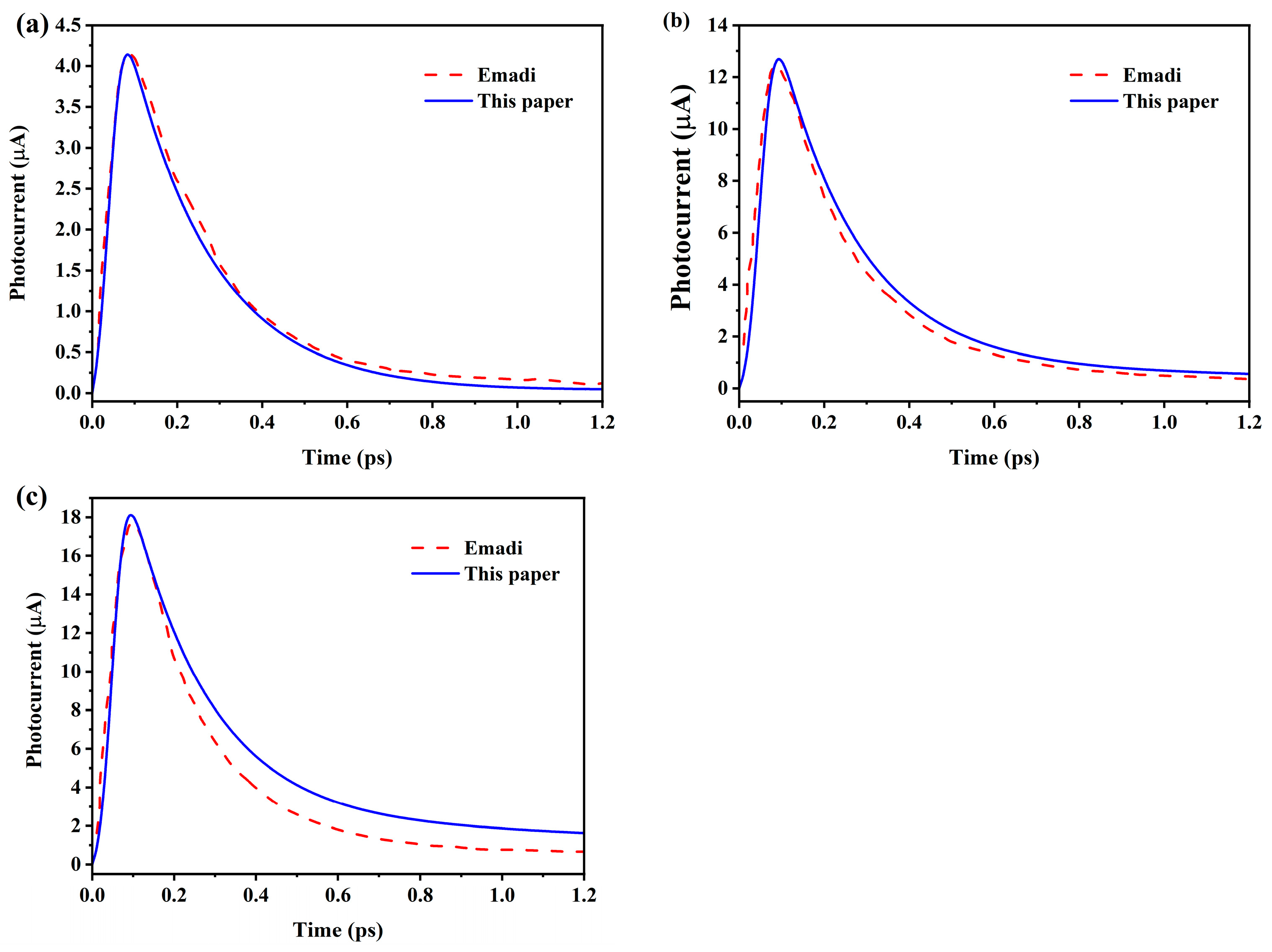
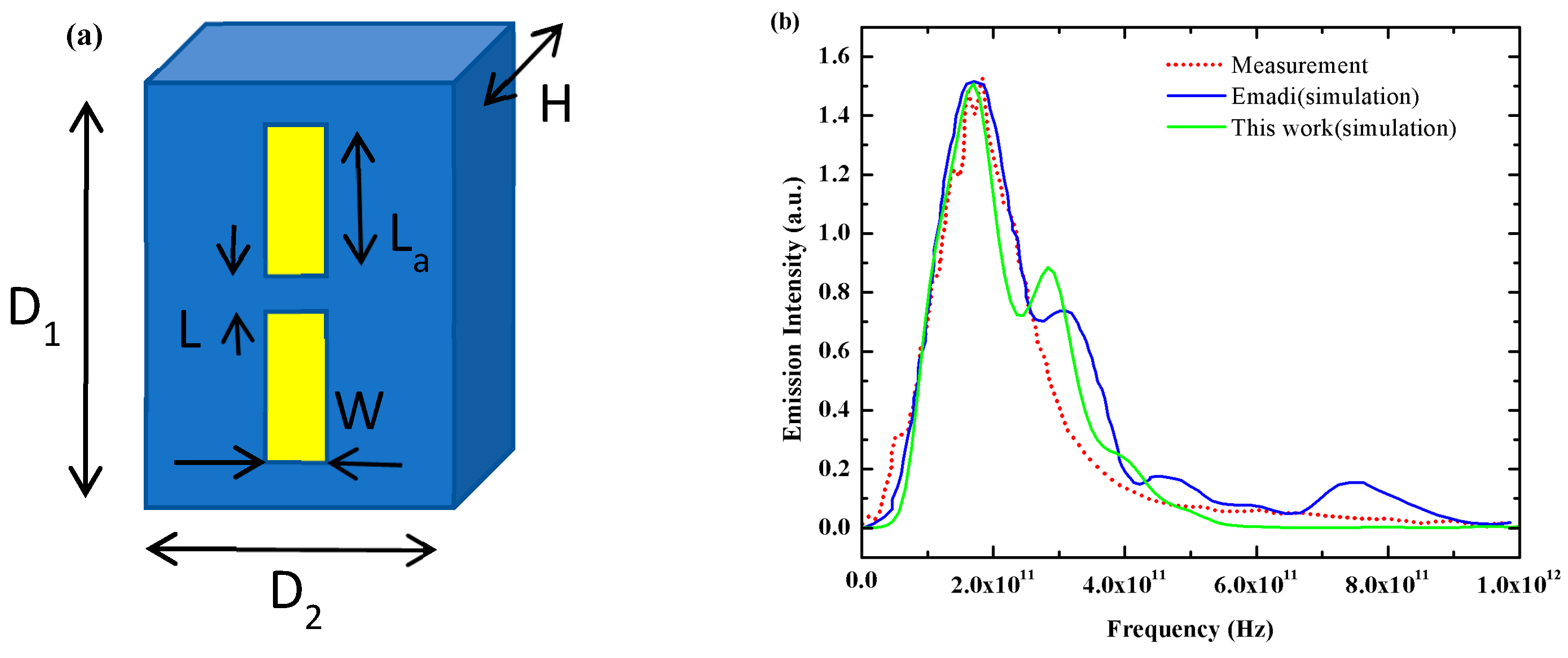
Under the model constructed in this paper, the incident parameters are the same as the model designed by Emadi et al. The transient photocurrents are shown in Figure 2. The peak currents of LE PCA, TE PCA, and IE PCA are 4.2 μA, 12.7 μA, and 18 μA, respectively, which are basically in good agreement with each other in terms of the magnitude of the peak current, and the degree of deviation is less than 5%. The simulation results of transient photocurrent under the model of this paper are very similar to those obtained under the energy balance transport model, thus verifying the validity of the model of this paper. In addition, we compared the THz-PCA emission intensity with the experimental results reported by Fumiaki Miyamaru et al. [33] and with the simulation results of Emadi et al. [25]. The substrate material, electrode geometry, and laser parameters were matched to those in the cited studies. As shown in Figure 3, the emission intensities are in good agreement, further validating the effectiveness of our model.
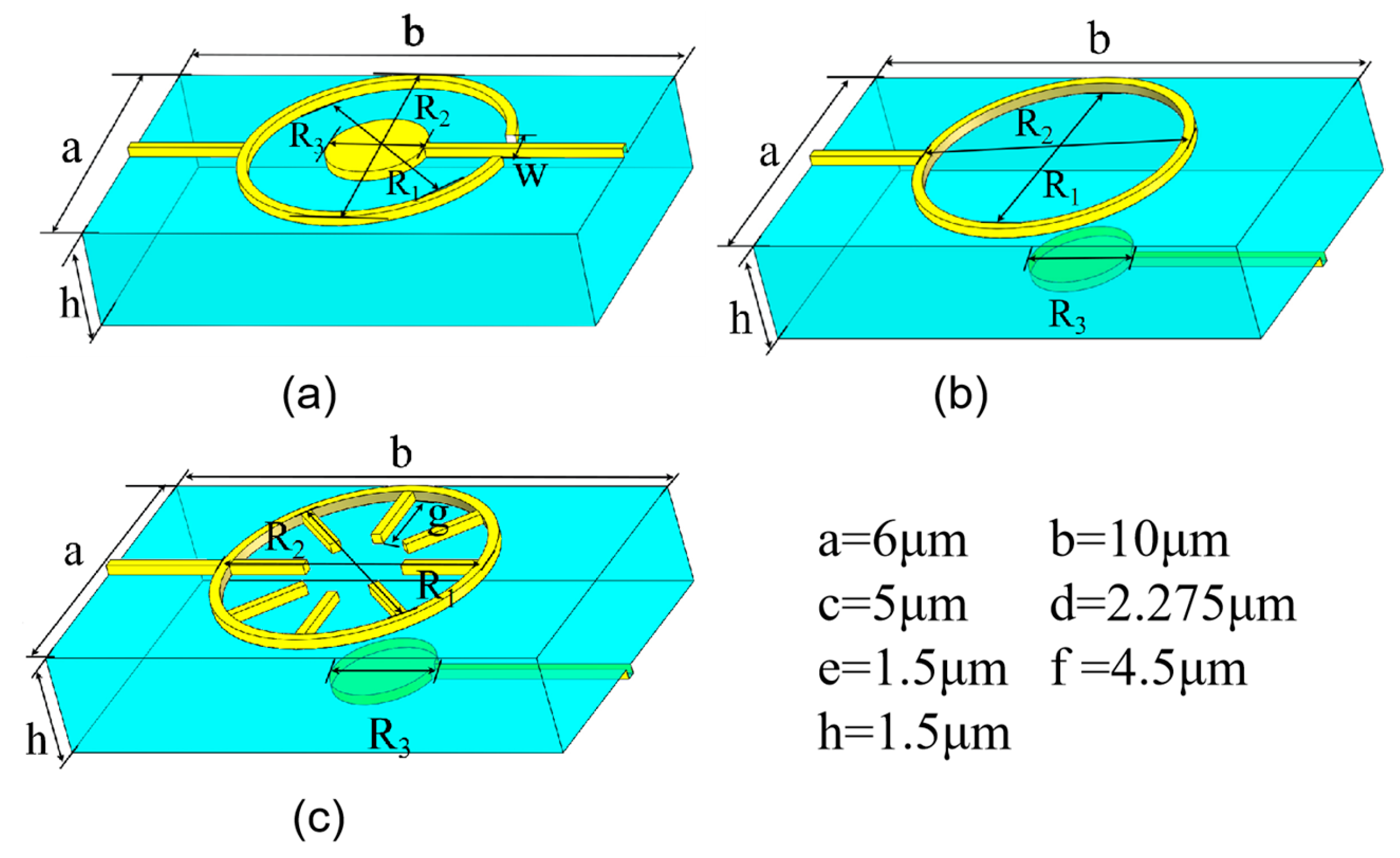
The graph designed in this paper mainly consists of a 1.5 μm thick substrate layer and a 0.2 μm thick electrode layer, as shown in Figure 4, where one of the electrodes is designed as a circle in order to maximize the use of the photogenerated carriers at the edges, which makes the photocurrent larger, where (a) means that both electrodes are on the same plane, (b) means that both electrodes are on different planes, and (c) means that eight metal tips are added to the circular electrode based on (b), and the thickness and width of the electrode layer are 0.2 μm. The three large metal rings are the same; the outer ring R2 = 2.7 μm, and R1 is equal to 2.5 μm. The small circle radius R3 = 1 μm. The length of the metal tip of the PCA-3 is 1.6 μm, and the width is 0.2 μm. We set the laser pulse center time (T0) to 0.5 ps to simulate the model. The parameters used for simulation are shown in Table 1.
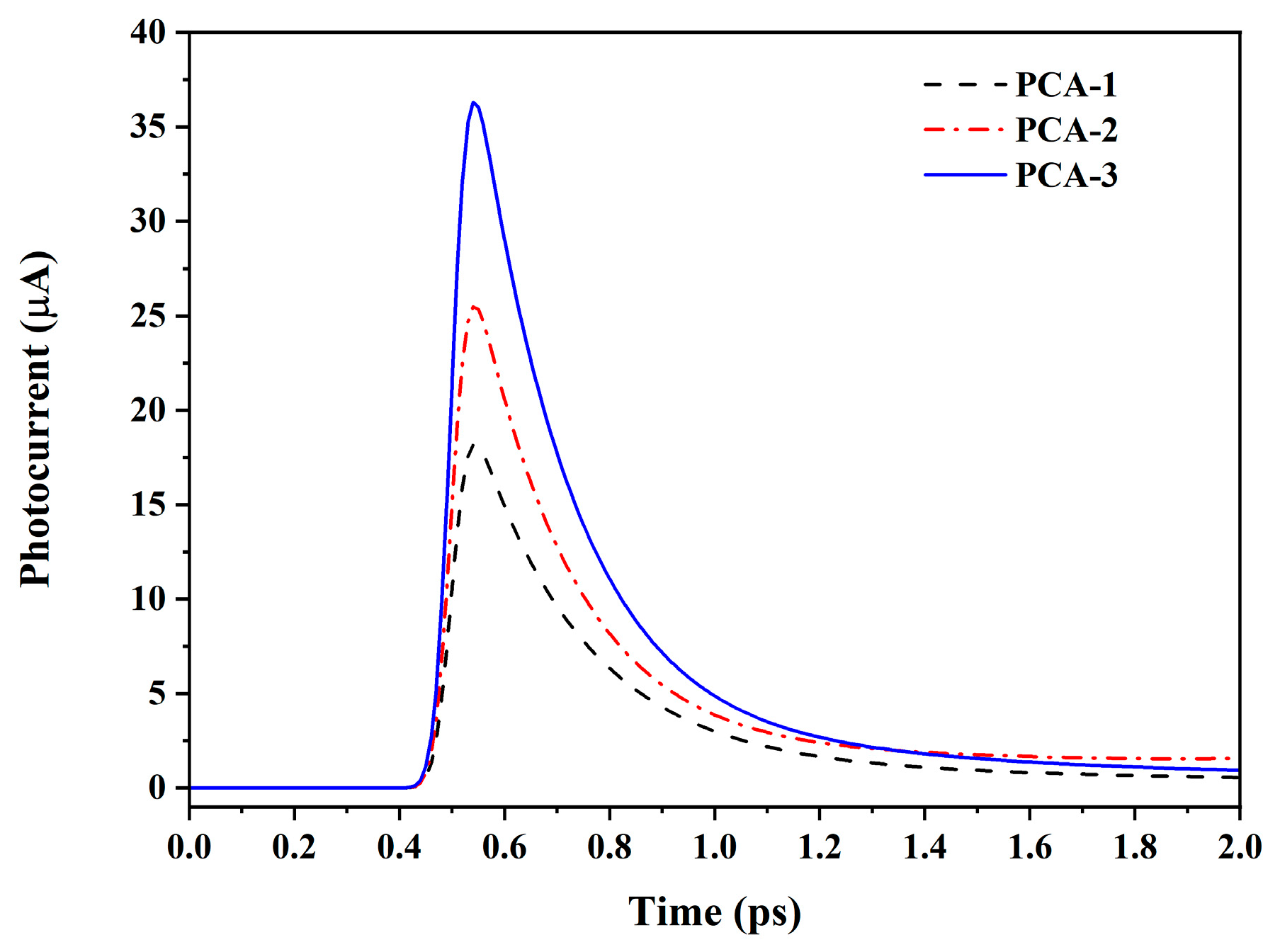
The results show that the photocurrent amplitude of PCA-1 is 18.1 μA, that of PCA-2 is 25.4 μA, and that of PCA-3 is 36.1 μA (Figure 5).
Under the model constructed in this paper, the transient photocurrents generated by the PCA under 800 nm laser irradiation with different incident laser average powers (10 mW, 15 mW, 20 mW, 25 mW, and 30 mW) are first simulated when the bias voltage is 20 V. The results are shown in Figure 6.
Figure 6 show that under a certain bias voltage, the transient photocurrent increases with the increase of the average power of the incident laser, but the curve decreases faster after reaching the peak of the maximum transient photocurrent, which is mainly due to the following reasons: when the energy of the incident photon is higher than the bandgap energy of the semiconductor material, the photon is able to be absorbed by the electrons in the semiconductor, which enables the electrons to obtain enough energy to jump from the valence band to the conduction band, thus generating free electron and hole pairs. The higher the laser power, the more electron–hole pairs are excited per unit time. In the presence of an applied bias voltage, the newly created free electrons are driven towards the anode by the electric field, while the holes move towards the cathode. This carrier motion in the presence of an electric field leads to the generation of a current.
As the laser power increases, the photogenerated carrier density rises significantly, enhancing space-charge (and radiated-field) screening; this dynamic screening of the effective bias field leads to a steeper decay of the current density in THz-PCAs; meanwhile, recombination and diffusion may occur, but they are not the dominant cause of this steepening [34,35].
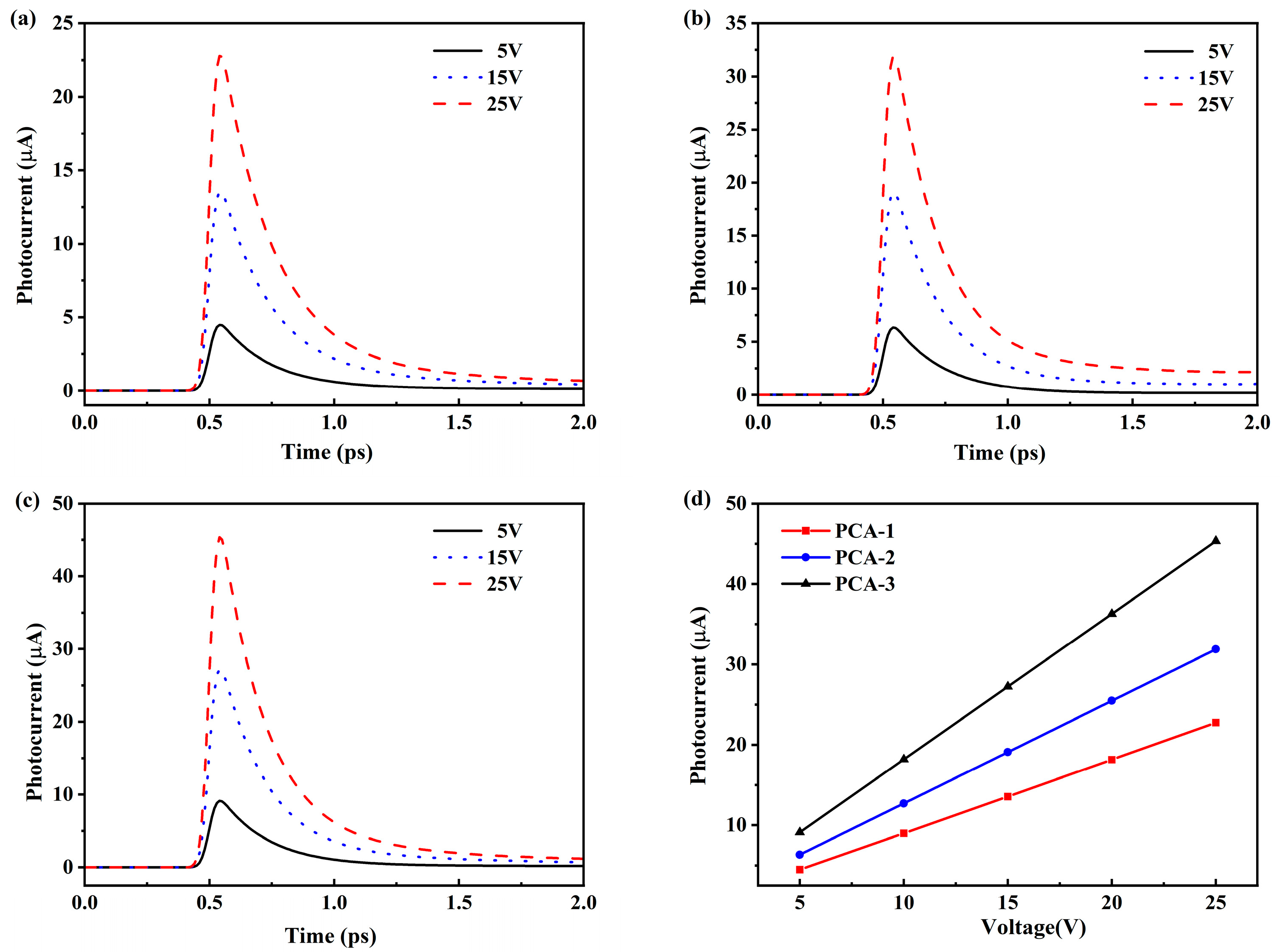
The transient photocurrents generated when the bias voltage is varied (10 V, 15 V, 20 V, 25 V, and 30 V) under the irradiation of an 800 nm laser with an average power of 10 mW of the incident laser are simulated, and the results are shown in Figure 7. The simulation results show that the transient photocurrent increases with the increase in the bias voltage under a certain average power of the incident laser, and the reasons are mainly composed of the following aspects: (1) high bias voltage can increase the carrier lifetime and reduce the recombination probability of carriers, which makes more carriers participate in the formation of the current; (2) under the forward bias condition, as the bias voltage rises, more carriers are injected into the depletion region of the photoconductor, and then under laser irradiation, more carriers can be separated and participate in the conduction, thus increasing the transient photocurrent. Meanwhile, it can be seen from the figure that with the increase in bias voltage, the time-varying curve of transient photocurrent is sharper at its current peak, which is caused by the fact that under a high bias electric field, the drift speed of carriers may exceed the speed of finally reaching the steady state, which leads to the phenomenon of velocity overshoot effect.
Photoconductive antennas (PCAs) operate by using ultrafast femtosecond laser pulses to irradiate a semiconductor substrate and excite the generation of photogenerated free carriers that are then accelerated by an externally biased electric field drive to form a transient current pulse. According to Maxwell’s system of equations, this rapidly changing current radiates terahertz waves. Under far-field conditions, the relationship between the generated photocurrent and the radiated THz field intensity is defined as [36].
E T H Z t = A 4 π ε 0 c 0 2 z d J t d t
where ε0 is the free-space dielectric constant, A is the illuminated area of the antenna gap, z is the observation point distance, J(t) is the photocurrent density, and c represents the speed of light in a vacuum. In Figure 8, the intensities of the radiated THz fields of the three THz-PCAs are obtained by deriving the variations of the photocurrents with time. The peak intensities of the radiated THz field (Epp) of PCA-3 (blue curve, Epp = 2.2) are about 0.45 and 1 times higher than those of PCA-2 (red curve, Epp = 1.5) and PCA-1 (black curve, Epp = 1.1), respectively. Finally, the time-domain signals of Epp were calculated to elucidate the effect of different Pave and Vbias on the output THz signal. In Figure 9a, the Epp of PCA-1 and PCA-2 is proportional to the average laser power, but the Epp of PCA-3 is not proportional to the average optical power due to the field shielding effect, which leads to the saturation effect at higher optical powers (at Pave > 20 mW). Figure 9b depicts the Epp of the three THz-PCAs proportional to the bias voltage as the carrier drift velocity increases with the bias voltage. Moreover, the radiation power of emitted THz waves PTHz is proportional to the squared intensity of the radiated THz field expressed as PTHz∝ETHz2, which means the radiation power from the proposed PCA-3 is up to four times stronger than that of the traditional PCA-1.
Vertical ring-disk electrodes (PCA-3) break the spatial symmetry through the anisotropic distribution of positive and negative electrodes [37,38] and use the metal tip to induce local field enhancement to break the symmetry of carrier transport. Meanwhile, the shortened cathode–anode spacing suppresses the carrier complex loss and enhances the radiation efficiency
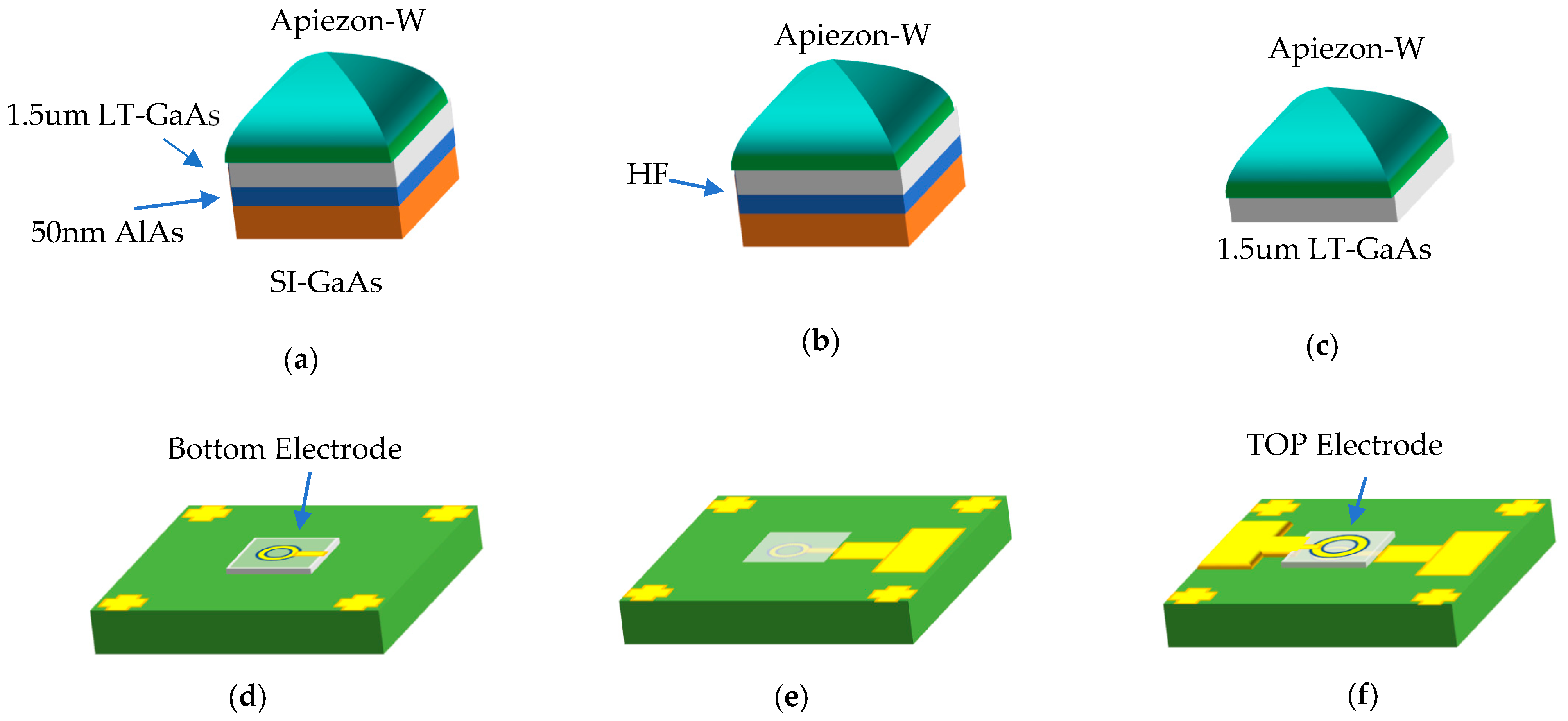
The THz-PCA fabrication flow is illustrated in Figure 10. On a semi-insulating GaAs (SI-GaAs) substrate, a 50 nm AlAs sacrificial layer and a 1.5 μm low-temperature GaAs layer are sequentially grown by molecular beam epitaxy (MBE). A protective coating (Apiezon-W dissolved in trichloroethylene) is drop-cast and low-temperature cured (Figure 10a); the AlAs sacrificial layer is selectively etched in dilute HF to release the LT-GaAs thin film, following the thin-film transfer and heterogeneous-integration approach for LTG-GaAs PCAs [39] (Figure 10b,c). The bottom electrode of the PCA is first defined on the bottom face of the LT-GaAs thin film by photolithography and metallization (Figure 10d). The film is then transferred onto an intrinsic Si host and aligned using precision alignment lithography (Figure 10e). On the Si host, metal interconnects/pads are patterned to contact the preformed bottom electrode, and the top electrode is deposited on the top surface of the LT-GaAs film (Figure 10f). To avoid disconnection caused by the step between the “top electrode” on the LT-GaAs layer and the Si substrate, a layer of SU-8-like organic material can be employed, as used by Yang et al. in their study, to reduce the step height [40]. Both electrodes consist of Ti/Au (5/50 nm) deposited by high-vacuum thermal evaporation [41]. Rapid thermal annealing is employed to optimize the metal/semiconductor contacts. Using AlAs sacrificial-layer etching and thin-film transfer, the Roger Dorsinville–Sang-Woo Seo group successfully fabricated thin-film LT-GaAs THz-PCAs [42].

3.2. The Performance Comparison

Under the same simulation parameters, the photocurrent magnitude of PCA-1 (18.1 μA) is basically equal to that of IE PCA (18 μA), the photocurrent magnitude of PCA-2 (25.4 μA) is enhanced by about 45% compared to that of IE PCA, and the photocurrent magnitude of PCA-3 (36.3 μA) is enhanced by about 100% compared to that of IE PCA. The analysis shows that the main reason for this is that, on the one hand, the PCA-1 and PCA-2 electrode structures increase the effective utilization area of the incident light compared to the conventional electrode structure, which can increase the area of the laser light incident to the substrate and thus improve the absorption rate of the light. The effective utilization area of the PCA-2 is more than that of the PCA-1, which makes the photocurrent magnitude of the PCA-2 45% larger than that of the PCA-1, and the PCA-3 has a higher photocurrent magnitude (36.3 μA) compared to the IE PCA. Meanwhile, the design of the electrode structure of PCA-3 reduces the distance between the anode and the cathode, which helps to reduce the distance of the photocarriers transported in the substrate and thus reduces the compound loss of the carriers, which improves the magnitude of the photocurrent and also improves the efficiency of the generation of terahertz waves. Prof. M. Jarrahi’s group has pioneered plasmonic photoconductive emitters by employing plasmonic contact electrodes to localize the optical field at the contacts and reduce the carrier transit length, thereby yielding substantial performance gains [43,44,45]. These designs rely on nanometer-scale patterning, whereas our approach uses conventional photolithography with micrometer-scale features, favoring process accessibility while remaining compatible with LT-GaAs thin-film heterogeneous integration flow.

4. Conclusions

In this paper, the model of a terahertz photoconductive antenna with positive and negative electrodes located on the top and bottom sides of the LT-GaAs substrate is constructed by using the finite element method, multiphysics field simulation method, and the transient photocurrent versus time curves and far-field intensities of the radiated terahertz field are obtained by simulation. In addition, the effects of electrode shape, average incident light intensity, bias voltage, and other factors on the transient photocurrent of the photoconductive antenna are also investigated in this paper. The results show that the peak current generated by a PCA-1 photoconductive antenna with both positive and negative electrodes on the same side of the substrate is about 18 μA, whereas the peak current generated by PCA-1 and the conventional interdigital photoconductive antenna are equal with the same simulation parameters, and the peak current generated by PCA-2 photoconductive antenna with the positive and negative electrodes at the top and bottom of the substrate is nearly 1.45 times of that generated by PCA-1. The PCA-3 photoconductive antenna, featuring positive and negative electrodes on opposite sides of the substrate and eight additional metal tips on the circular electrodes, generates nearly twice the peak current of PCA-1. Additionally, the terahertz radiated power of PCA-3 is four times higher than that of PCA-1. These results indicate that the proposed THz-PCA significantly enhances optical-terahertz conversion efficiency, offering substantial potential for advancing terahertz technology.

Author Contributions

Conceptualization, L.L.; Methodology: L.L.; Formal analysis, L.L., G.L., X.L., H.D. and Z.L.; Investigation, H.D., G.L., X.L. and Z.L.; Software, H.D. and Z.L.; Writing—original draft preparation, H.D. and L.L.; Writing—review and editing, L.L., Z.L. and H.D.; Visualization, H.D. and Z.L.; Data curation, Z.L.; Supervision: L.L., Resources: S.S.; Project administration, L.L. and S.S.; Funding acquisition, L.L. All authors have read and agreed to the published version of the manuscript.

Funding

This research was funded by the Science and Technology Base and Talent Special Project of Guangxi (No. GuiKeAD20238095), the National Natural Science Foundation of China (No. 61964003), Guilin Innovation Platform and Talent Plan (No. 20210217-9), the Guangxi Key Laboratory of Brain-inspired Computing and Intelligent Chips (No. BCIC-24-Z2 and BCIC-24-K12), the University-Enterprise Cooperation Program of School of Electronic Information and Modern Industry, Guangxi Normal University, and the Program of Guangxi Universities Engineering Research Center for Optoelectronic Information Technology.

Institutional Review Board Statement

Not applicable.

Informed Consent Statement

Not applicable.

Data Availability Statement

The data supporting the findings of this study are available from the corresponding author upon reasonable request.

Conflicts of Interest

The research was conducted in the absence of any commercial or financial relationships that could be construed as a potential conflict of interest.

References

  1. Ferguson, B.; Zhang, X.-C. Materials for Terahertz Science and Technology. Nat. Mater. 2002, 1, 26–33. [Google Scholar] [CrossRef]
  2. Mittleman, D.M. Perspective: Terahertz Science and Technology. J. Appl. Phys. 2017, 122, 230901. [Google Scholar] [CrossRef]
  3. Meng, D.; Liu, J.; Chen, W.; Cheng, Y.-Y.; You, K.-W.; Fan, Z.-C.; Ye, Q.; Huang, P.-H.; Chen, Y.-S. Study on the Enhancement Mechanism of Terahertz Molecular Fingerprint Sensing. Results Phys. 2022, 39, 105766. [Google Scholar] [CrossRef]
  4. Redo-Sanchez, A.; Heshmat, B.; Aghasi, A.; Naqvi, S.; Zhang, M.; Romberg, J.; Raskar, R. Terahertz Time-Gated Spectral Imaging for Content Extraction through Layered Structures. Nat. Commun. 2016, 7, 12665. [Google Scholar] [CrossRef] [PubMed]
  5. Zhang, S.; Zheng, Z.; Zhang, M.; Zhang, T.; Zhang, Z.; Huang, H. The Application of THz-TDS in the Characterization of Bayan Obo Magnetite Ore Composition. Sci. Rep. 2024, 14, 15033. [Google Scholar] [CrossRef] [PubMed]
  6. Bao, R.; Qin, F.; Chen, R.; Chen, S.; Zhan, H.; Zhao, K.; Yue, W. Optical Detection of Oil Bearing in Reservoir Rock: Terahertz Spectroscopy Investigation. IEEE Access 2019, 7, 121755–121759. [Google Scholar] [CrossRef]
  7. Zhu, J.; Li, C.; Fang, B.; Lu, J.; Hong, Z.; Jing, X. Advancements in Biosensing Detection Based on Terahertz Metasurfaces. Opt. Laser Technol. 2024, 176, 110978. [Google Scholar] [CrossRef]
  8. Shao, Y.; Zhou, Y.; Wan, J.; Zhu, Z.; Peng, Y.; Zhao, C.; Zhu, Y.; Tang, W. Using Terahertz Spectroscopy to Quantify Bioactive Flavonoids in Moxa Wool as Predictor of Rheumatoid Arthritis Treatment Outcomes. Phytomedicine 2024, 133, 155927. [Google Scholar] [CrossRef]
  9. Ahmadivand, A.; Gerislioglu, B.; Ramezani, Z.; Kaushik, A.; Manickam, P.; Ghoreishi, S.A. Functionalized Terahertz Plasmonic Metasensors: Femtomolar-Level Detection of SARS-CoV-2 Spike Proteins. Biosens. Bioelectron. 2021, 177, 112971. [Google Scholar] [CrossRef]
  10. Li, J.; Li, X.; Yardimci, N.T.; Hu, J.; Li, Y.; Chen, J.; Hung, Y.-C.; Jarrahi, M.; Ozcan, A. Rapid Sensing of Hidden Objects and Defects Using a Single-Pixel Diffractive Terahertz Sensor. Nat. Commun. 2023, 14, 6791. [Google Scholar] [CrossRef]
  11. Akyildiz, I.F.; Han, C.; Hu, Z.; Nie, S.; Jornet, J.M. Terahertz Band Communication: An Old Problem Revisited and Research Directions for the Next Decade. IEEE Trans. Commun. 2022, 70, 4250–4285. [Google Scholar] [CrossRef]
  12. Kumar, A.; Gupta, M.; Pitchappa, P.; Wang, N.; Szriftgiser, P.; Ducournau, G.; Singh, R. Phototunable Chip-Scale Topological Photonics: 160 Gbps Waveguide and Demultiplexer for THz 6G Communication. Nat. Commun. 2022, 13, 5404. [Google Scholar] [CrossRef]
  13. Li, X.; Li, J.; Li, Y.; Ozcan, A.; Jarrahi, M. High-Throughput Terahertz Imaging: Progress and Challenges. Light Sci. Appl. 2023, 12, 233. [Google Scholar] [CrossRef] [PubMed]
  14. Yu, Q.; Cai, H.; Zhu, X.; Liu, Z.; Yin, H.; Li, L. Terahertz Bistatic Three-Dimensional Computational Imaging of Hidden Objects through Random Media. Sci. Rep. 2024, 14, 6147. [Google Scholar] [CrossRef] [PubMed]
  15. He, Y.; Chen, Y.; Zhang, L.; Wong, S.-W.; Chen, Z.N. An Overview of Terahertz Antennas. China Commun. 2020, 17, 124–165. [Google Scholar] [CrossRef]
  16. Lepeshov, S.; Gorodetsky, A.; Krasnok, A.; Rafailov, E.; Belov, P. Enhancement of Terahertz Photoconductive Antenna Operation by Optical Nanoantennas. Laser Photonics Rev. 2017, 11, 1600199. [Google Scholar] [CrossRef]
  17. Loata, G.C.; Thomson, M.D.; Löffler, T.; Roskos, H.G. Radiation Field Screening in Photoconductive Antennae Studied via Pulsed Terahertz Emission Spectroscopy. Appl. Phys. Lett. 2007, 91, 232506. [Google Scholar] [CrossRef]
  18. Burford, N.M.; El-Shenawee, M.O. Review of Terahertz Photoconductive Antenna Technology. Opt. Eng. 2017, 56, 010901. [Google Scholar] [CrossRef]
  19. Wang, D.; Yang, L.; Hu, Z.; Wang, F.; Yang, Y.; Pan, X.; Dong, Z.; Tian, S.; Zhang, L.; Han, L.; et al. Antiferromagnetic Semimetal Terahertz Photodetectors Enhanced through Weak Localization. Nat. Commun. 2025, 16, 25. [Google Scholar] [CrossRef]
  20. Zhang, J.; Hu, Z.; Yang, Q.; Sun, S.; Liu, F.; Xu, H.; Wang, X.; Zhao, Y.; Zhou, N.; Dong, G.; et al. Strong Anisotropy and Giant Photothermoelectricity of 1D Alloy Nb3 Se12 I-Based Photodetector for Ultrabroadband Light-Detection and Encryption Imaging Application. Adv. Mater. 2025, 37, 2410275. [Google Scholar] [CrossRef]
  21. Auston, D.H.; Cheung, K.P.; Smith, P.R. Picosecond Photoconducting Hertzian Dipoles. Appl. Phys. Lett. 1984, 45, 284–286. [Google Scholar] [CrossRef]
  22. Park, S.-G.; Jin, K.H.; Yi, M.; Ye, J.C.; Ahn, J.; Jeong, K.-H. Enhancement of Terahertz Pulse Emission by Optical Nanoantenna. ACS Nano 2012, 6, 2026–2031. [Google Scholar] [CrossRef] [PubMed]
  23. Park, S.-G.; Choi, Y.; Oh, Y.-J.; Jeong, K.-H. Terahertz Photoconductive Antenna with Metal Nanoislands. Opt. Express 2012, 20, 25530. [Google Scholar] [CrossRef] [PubMed]
  24. Cox Iii, C.H.; Diadiuk, V.; Yao, I.; Leonberger, F.J.; Williamson, R.C. InP Optoelectronic Switches And Their High-Speed Signal-Processiny Applications. In Proceedings of the 27th Annual Technical Symposium, San Diego, CA, USA, 28 November 1983; pp. 164–168. [Google Scholar]
  25. Emadi, R.; Barani, N.; Safian, R.; Nezhad, A.Z. Hybrid Computational Simulation and Study of Terahertz Pulsed Photoconductive Antennas. J. Infrared Millim. Terahertz Waves 2016, 37, 1069–1085. [Google Scholar] [CrossRef]
  26. Maussang, K.; Palomo, J.; Mangeney, J.; Dhillon, S.S.; Tignon, J. Large-Area Photoconductive Switches as Emitters of Terahertz Pulses with Fully Electrically Controlled Linear Polarization. Opt. Express 2019, 27, 14784. [Google Scholar] [CrossRef]
  27. Sotoodeh, M.; Khalid, A.H.; Rezazadeh, A.A. Empirical Low-Field Mobility Model for III–V Compounds Applicable in Device Simulation Codes. J. Appl. Phys. 2000, 87, 2890–2900. [Google Scholar] [CrossRef]
  28. Jiang, X.-Q.; Fan, W.-H.; Song, C.; Chen, X.; Wu, Q. Terahertz Photoconductive Antenna Based on Antireflection Dielectric Metasurfaces with Embedded Plasmonic Nanodisks. Appl. Opt. 2021, 60, 7921. [Google Scholar] [CrossRef]
  29. Burford, N.; El-Shenawee, M. Computational Modeling of Plasmonic Thin-Film Terahertz Photoconductive Antennas. J. Opt. Soc. Am. B 2016, 33, 748. [Google Scholar] [CrossRef]
  30. Bashirpour, M.; Poursafar, J.; Kolahdouz, M.; Hajari, M.; Forouzmehr, M.; Neshat, M.; Hajihoseini, H.; Fathipour, M.; Kolahdouz, Z.; Zhang, G. Terahertz Radiation Enhancement in Dipole Photoconductive Antenna on LT-GaAs Using a Gold Plasmonic Nanodisk Array. Opt. Laser Technol. 2019, 120, 105726. [Google Scholar] [CrossRef]
  31. Amirjani, A.; Sadrnezhaad, S.K. Computational Electromagnetics in Plasmonic Nanostructures. J. Mater. Chem. C 2021, 9, 9791–9819. [Google Scholar] [CrossRef]
  32. Lesina, A.C.; Vaccari, A.; Berini, P.; Ramunno, L. On the Convergence and Accuracy of the FDTD Method for Nanoplasmonics. Opt. Express 2015, 23, 10481. [Google Scholar] [CrossRef]
  33. Miyamaru, F.; Saito, Y.; Yamamoto, K.; Furuya, T.; Nishizawa, S.; Tani, M. Dependence of Emission of Terahertz Radiation on Geometrical Parameters of Dipole Photoconductive Antennas. Appl. Phys. Lett. 2010, 96, 211104. [Google Scholar] [CrossRef]
  34. Jepsen, P.U.; Jacobsen, R.H.; Keiding, S.R. Generation and Detection of Terahertz Pulses from Biased Semiconductor Antennas. J. Opt. Soc. Am. B 1996, 13, 2424. [Google Scholar] [CrossRef]
  35. Rodriguez, G.; Taylor, A.J. Screening of the Bias Field in Terahertz Generation from Photoconductors. Opt. Lett. 1996, 21, 1046. [Google Scholar] [CrossRef] [PubMed]
  36. Tong-Yi, Z.; Jun-Cheng, C. Study of the Surface and Far Fields of Terahertz Radiation Generated by Large-Aperture Photoconductive Antennas. Chin. Phys. 2004, 13, 1742–1746. [Google Scholar] [CrossRef]
  37. Atalla, M.R.M.; Jiang, Z.; Liu, J.; Wang, L.; Ashok, S.; Xu, J. Modeling the Spectral Responsivity of Ultraviolet GaN Schottky Barrier Photodetectors under Reverse Bias. J. Appl. Phys. 2015, 117, 134503. [Google Scholar] [CrossRef]
  38. Long, J.W.; Dunn, B.; Rolison, D.R.; White, H.S. Three-Dimensional Battery Architectures. Chem. Rev. 2004, 104, 4463–4492. [Google Scholar] [CrossRef]
  39. Yablonovitch, E.; Gmitter, T.; Harbison, J.P.; Bhat, R. Extreme Selectivity in the Lift-off of Epitaxial GaAs Films. Appl. Phys. Lett. 1987, 51, 2222–2224. [Google Scholar] [CrossRef]
  40. Yang, Z.; Albrow-Owen, T.; Cui, H.; Alexander-Webber, J.; Gu, F.; Wang, X.; Wu, T.-C.; Zhuge, M.; Williams, C.; Wang, P.; et al. Single-Nanowire Spectrometers. Science 2019, 365, 1017–1020. [Google Scholar] [CrossRef]
  41. Patkar, M.P.; Chin, T.P.; Woodall, J.M.; Lundstrom, M.S.; Melloch, M.R. Very Low Resistance Nonalloyed Ohmic Contacts Using Low-Temperature Molecular Beam Epitaxy of GaAs. Appl. Phys. Lett. 1995, 66, 1412–1414. [Google Scholar] [CrossRef]
  42. Ríos, R.D.V.; Bikorimana, S.; Ummy, M.A.; Dorsinville, R.; Seo, S.-W. A Bow-Tie Photoconductive Antenna Using a Low-Temperature-Grown GaAs Thin-Film on a Silicon Substrate for Terahertz Wave Generation and Detection. J. Opt. 2015, 17, 125802. [Google Scholar] [CrossRef]
  43. Yardimci, N.T.; Lu, H.; Jarrahi, M. High Power Telecommunication-Compatible Photoconductive Terahertz Emitters Based on Plasmonic Nano-Antenna Arrays. Appl. Phys. Lett. 2016, 109, 191103. [Google Scholar] [CrossRef]
  44. Yardimci, N.T.; Jarrahi, M. High Sensitivity Terahertz Detection through Large-Area Plasmonic Nano-Antenna Arrays. Sci. Rep. 2017, 7, 42667. [Google Scholar] [CrossRef]
  45. Berry, C.W.; Wang, N.; Hashemi, M.R.; Unlu, M.; Jarrahi, M. Significant Performance Enhancement in Photoconductive Terahertz Optoelectronics by Incorporating Plasmonic Contact Electrodes. Nat. Commun. 2013, 4, 1622. [Google Scholar] [CrossRef]
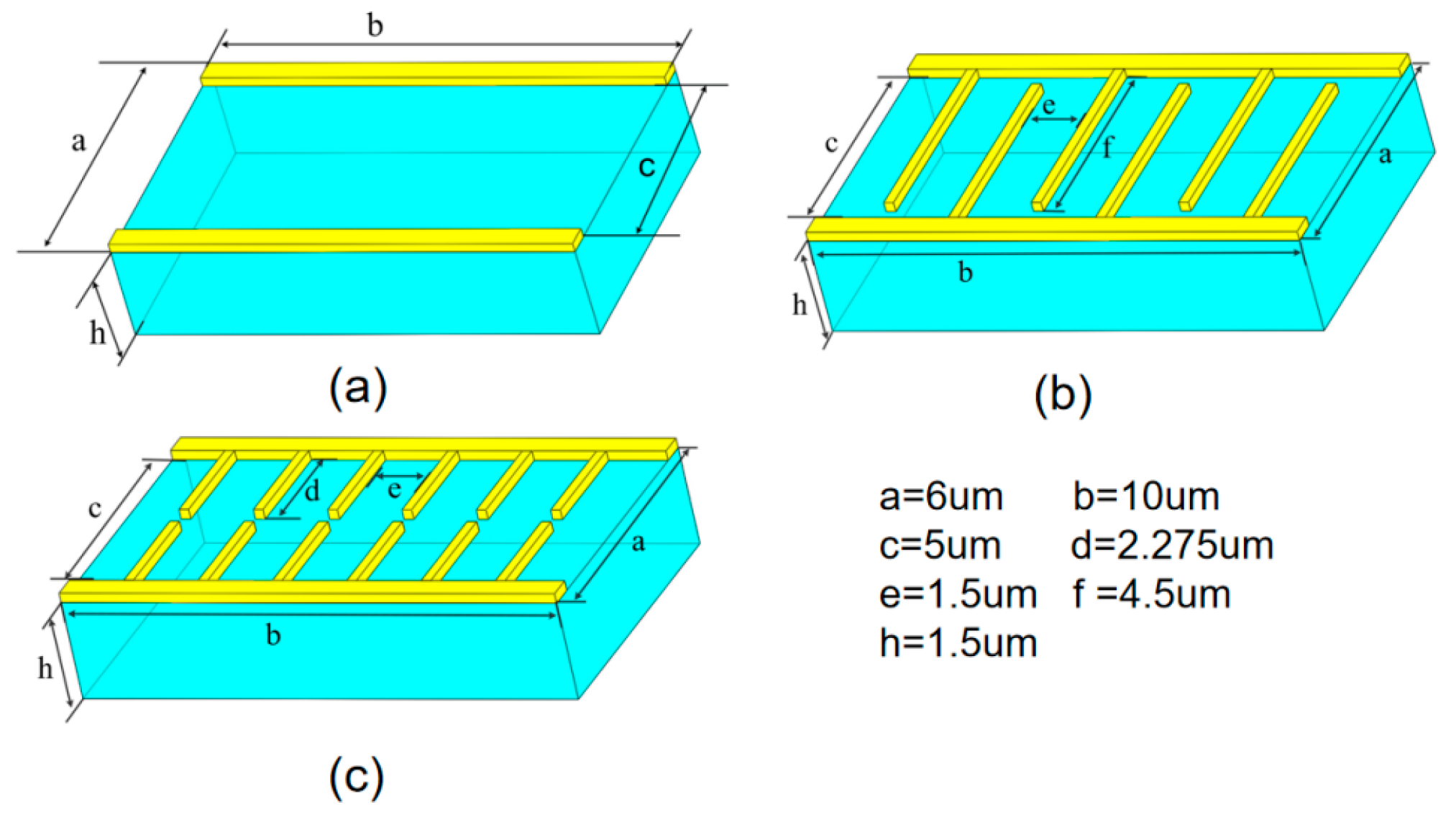
Figure 1. Schematic diagram of the structure and parameters of the photoconductive antenna designed by Emadi et al. (a) Line electron, (b) interdigitated electron, (c) tip-to-tip electron.
Photonics 12 01116 g001
Figure 2. Schematic diagram of the transient photocurrent of the photoconductive antenna designed by Emadi et al. and the photoconductive antenna modeled in this paper: (a) bare gap, (b) tip-to-tip electron, (c) interdigitated electron.
Photonics 12 01116 g002
Figure 3. (a) Three-dimensional view of the dipole THz-PCA with D1 = D2 = 400 μm, H = 0.04 La, La = 97.5 μm, L = 5 μm, and W = 10 μm; (b) comparison of simulated and measured detected THz signals: Emadi et al.—simulation [25], measurement [33]—versus this work (simulation).
Photonics 12 01116 g003
Figure 4. Structural schematics and parameters of photoconductive antennas: (a) PCA-1, (b) PCA-2, and (c) PCA-3.
Photonics 12 01116 g004
Figure 5. Transient photocurrent for photoconductive antennas PCA-1, PCA-2, and PCA-3.
Photonics 12 01116 g005
Figure 6. Transient photocurrent of photoconductive antenna under different light intensities at a bias voltage of Vbias = 20 V: (a) PCA-1, (b) PCA-2, (c) PCA-3, (d) photocurrent amplitude as a function of average optical power intensity.
Photonics 12 01116 g006
Figure 7. Schematic diagram of transient photocurrent of photoconductive antenna at different voltages (average laser power Pave = 10 mW): (a) PCA-1, (b) PCA-2, (c) PCA-3 (d) photocurrent amplitude as a function of bias voltage.
Photonics 12 01116 g007
Figure 8. Far-field intensity of the radiated terahertz field.
Photonics 12 01116 g008
Figure 9. Inter-peak intensity of the radiated THz field as a function of (a) average laser power (bias voltage Vbias = 20 V) and (b) bias voltage (average laser power Pave = 10 mW).
Photonics 12 01116 g009
Figure 10. LT-GaAs thin-film device integration on the intrinsic silicon substrate. (a) Apply Apiezon W to the LT-GaAs surface; (b) etch the AlAs layer with HF; (c) etch away the SI-GaAs substrate to obtain the LT-GaAs thin layer; (d) flip and transfer the LT-GaAs onto an intrinsic silicon substrate and deposit a bottom electrode on the underside; (e) with the front side up, transfer the LT-GaAs onto another intrinsic silicon substrate prepatterned with bottom-electrode contact metal; (f) fabricate the top electrode.
Photonics 12 01116 g010
Table 1. Parameters used in Equations (1)–(13).
SymbolDescriptionValue
λFree-space wavelength800 [nm]
PaveAverage laser power10 [mW]
fpLaser repetition rate80 [MHz]
x0Pulse x-axis center location3 [µm]
t0Pulse center location (time)60 [fs]
Dx = DyPulse half-power beam width (x = y direction)2.5 [µm]
DtLaser pulse duration50 [fs]
n1 + ik1LT-GaAs at 800 nm3.68 + 0.06i
n2 + ik2Au at 800 nm0.15 + 4.91i
µrMagnetic permeability (all)1
âePolarization vectorâx
εrLT-GaAs Relative permittivity13.18
NcConduction band density of states9 × 1018 [1/cm3]
NvValence band density of states4.7 × 1017 [1/cm3]
µnElectron mobility0.04 [m2/V/s]
µpHole mobility0.01 [m2/V/s]
CnAuger electron coefficient7 × 10−30
CpAuger hole coefficient7 × 10−30
EgBandgap1.424 [V]
χElectron affinity4.07 [V]
γpHole degeneracy factor4
γnElectron degeneracy factor2
ni,effEffective intrinsic carrier concentration1.23 × 10−12 [1/m3]
σLT-GaAs electrical conductivity1.1 × 103 [S/m]
TRoom temperature300 [K]
τn = τpElectron/hole lifetime0.1 [ps]/0.1 [ps]
VbiasDC bias voltage20 [V]
kpcPhotoconductor extinction coefficient0.0625
Disclaimer/Publisher’s Note: The statements, opinions and data contained in all publications are solely those of the individual author(s) and contributor(s) and not of MDPI and/or the editor(s). MDPI and/or the editor(s) disclaim responsibility for any injury to people or property resulting from any ideas, methods, instructions or products referred to in the content.