Abstract
To support mode-division multiplexing with reduced inter-modal crosstalk, we propose a novel polarization-maintaining few-mode fiber design with a uniform doping profile and no air holes. The fiber employs two placed low-index inclusions to lift modal degeneracy and achieve strong birefringence while maintaining compatibility with standard MCVD and OVD fabrication processes. A genetic algorithm is used to optimize the geometrical and refractive index parameters. Finite element simulations show that the optimized design supports ten guided modes with a minimum effective index difference exceeding across the C+L band. The fiber exhibits moderate dispersion and strong modal isolation. Tolerance analysis confirms good robustness against index fluctuations and moderate sensitivity to dimensional variations. These features suggest that the proposed PM-FMF is a promising candidate for short-reach spatial-division multiplexing applications where intrinsic polarization and mode separation are desired.
1. Introduction
Over the past few decades, the relentless growth in global data traffic—driven by cloud computing, video streaming, artificial intelligence, and the proliferation of connected devices—has imposed unprecedented demands on optical communication networks. Conventional single-mode fiber (SMF) systems, despite remarkable advances through high-order modulation formats, coherent detection, and sophisticated digital signal processing (DSP), are gradually approaching their fundamental Shannon capacity limit, constrained by optical nonlinearities and amplifier noise. To sustain the exponential increase in network capacity, researchers have been exploring new physical dimensions for multiplexing beyond wavelength and polarization.
Among the emerging approaches, space-division multiplexing (SDM) has attracted extensive attention as a promising route to overcome the capacity ceiling by enabling multiple spatial channels within a single optical fiber [1,2,3,4]. SDM can be implemented using multi-core fibers (MCFs), which physically separate channels into distinct cores, or few-mode fibers (FMFs), which allow several orthogonal spatial modes to propagate within the same core. The FMF approach offers higher integration density and potentially better compatibility with existing optical components, making it a strong candidate for next-generation short-reach and long-haul transmission systems.
A major bottleneck in the practical deployment of FMF-based SDM systems, however, is the presence of inter-modal crosstalk. Mode coupling, caused by core ellipticity, microbending, or refractive-index fluctuations, leads to power exchange between modes and degrades signal integrity. To compensate for this impairment, multi-input multi-output (MIMO) DSP has been widely adopted at the receiver to decouple mixed spatial channels [5,6,7,8]. Although MIMO algorithms have proven highly effective in suppressing crosstalk and restoring orthogonality [9], their computational load scales quadratically with the number of modes. This scaling introduces significant challenges in high-capacity systems, where power efficiency, latency, and hardware complexity are critical constraints [10,11].
These limitations have motivated the development of new fiber designs that can inherently suppress mode coupling and thereby alleviate DSP complexity [12,13]. In this context, polarization-maintaining few-mode fibers (PM-FMFs) have emerged as a promising candidate. By providing well-separated spatial and polarization channels, PM-FMFs can substantially reduce, or even eliminate, the need for complex MIMO processing [14,15,16,17,18]. Such fibers could enable low-power, low-latency transmission systems ideally suited for high-density interconnects in data centers and short-reach optical networks.
Despite these advantages, PM-FMFs face considerable fabrication challenges. Conventional implementations rely on elliptical or asymmetric core structures to lift mode degeneracy and introduce birefringence. Achieving these geometries demands stringent control during preform manufacturing and core alignment, resulting in increased fabrication cost, complexity, and yield loss [19,20]. To address these challenges, Gu et al. recently proposed a PM-FMF architecture utilizing symmetrically positioned air holes to induce birefringence while maintaining geometric simplicity [21]. While this approach improves polarization selectivity, it introduces new manufacturing difficulties associated with precise air-hole pressure control during fiber drawing, which can compromise reproducibility and long-term stability [22].
In this work, we propose a novel PM-FMF design that eliminates the need for air holes altogether. Instead, we employ strategically positioned low-refractive-index regions to achieve both spatial and polarization mode separation. This design is fully compatible with standard modified chemical vapor deposition (MCVD) and outside vapor deposition (OVD) processes, significantly simplifying fabrication while maintaining excellent modal discrimination. A genetic algorithm (GA) is used to optimize the fiber geometry, leading to strong mode isolation with a minimum effective index difference () exceeding at 1550 nm for up to ten supported modes, as verified through finite element method (FEM) simulations.
The proposed structure achieves a favorable balance between optical performance and manufacturability. Its simple refractive index profile and robust polarization selectivity make it particularly suitable for compact, high-density SDM systems where minimizing DSP complexity directly translates into reduced power consumption, latency, and overall system cost. This work thus provides a practical and scalable path toward next-generation SDM transmission links, bridging the gap between theoretical capacity scaling and manufacturable optical fiber technologies.
2. Fiber Structure
Figure 1d,e illustrate the proposed polarization-maintaining few-mode fiber (PM-FMF) structure, which is designed to achieve strong modal and polarization separation without relying on air holes or complex core deformation. The fiber comprises an asymmetrical core region formed by a high-index doped material, such as germanium-doped silica, with a refractive index at 1550 nm. This central region functions as the main light-guiding core, enclosed within a circular boundary of radius R. The refractive index contrast between the core and the surrounding cladding ensures efficient optical confinement of the supported modes.
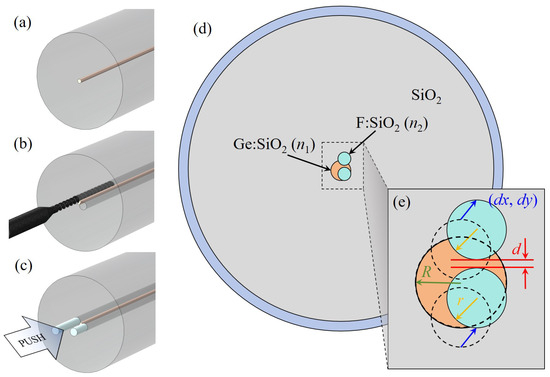
Figure 1.
(a–c) Schematic of the preform fabrication process: (a) fabrication of the preform by modified chemical vapor deposition (MCVD), (b) drilling of air holes into the preform, and (c) insertion of fluorine-doped glass rods into the holes. (d) Cross-sectional view of the proposed fiber structure; (e) definition of geometric parameters.
The intentional asymmetry in the fiber cross section is introduced during the preform fabrication stage. Specifically, two circular regions are embedded within the high-index core region. After fiber drawing, these embedded regions have a radius r and a center-to-center separation d, as shown schematically in Figure 1e. These regions are filled with a low-index doped material, such as fluorine-doped silica with refractive index at 1550 nm, thereby inducing localized reductions in the effective refractive index. The resulting refractive index perturbation acts as a controlled birefringence-inducing mechanism, effectively lifting the degeneracy between spatial and polarization modes.
The two low-index regions are positioned symmetrically with respect to the fiber’s central axis and aligned along the y-axis. Their centers are defined by coordinates relative to the geometric center of the enclosing core circle, which serves as the origin of the coordinate system. The symmetry along one axis and asymmetry along the orthogonal direction together produce a controlled anisotropy in the refractive index profile, leading to stable polarization-maintaining characteristics and minimal inter-modal coupling.
A feasible and manufacturable process flow for realizing the proposed structure is shown in Figure 1a–c. The preform fabrication begins with the conventional modified chemical vapor deposition (MCVD) method, which allows precise control of dopant concentration and refractive index distribution. Following deposition, the rod-in-tube (RIT) technique is employed to assemble the core and cladding components. In this process, the low-index rods—corresponding to the two circular depressions in the final structure—are inserted into pre-drilled slots within the high-index core rod. This assembly is then sleeved with a pure silica cladding tube and subsequently consolidated under high temperature in a controlled atmosphere.
This hybrid MCVD-RIT approach offers multiple advantages: (1) it ensures excellent control over the geometry and dopant profile of the low-index inclusions; (2) it maintains compatibility with standard fiber fabrication infrastructure, avoiding the need for complex pressure control systems associated with air-hole structures; and (3) it provides high reproducibility and yield, even for fibers with tight geometric tolerances.
After preform consolidation, the drawing process is carried out under optimized temperature and tension conditions to preserve the designed dimensions (R, r, and d). The resulting fiber exhibits stable birefringence and low polarization crosstalk over a broad wavelength range, confirming the robustness of the structural design.
In summary, the proposed PM-FMF architecture combines geometric simplicity with manufacturability, achieving polarization-maintaining performance through all-solid refractive index engineering rather than structural voids or elliptical deformations. This design philosophy not only simplifies fabrication but also ensures long-term environmental stability, making it particularly suitable for scalable SDM deployment in data-center and short-reach optical links.
3. Optimization and Discussion
3.1. The Variation of Refractive Index with Wavelength
To characterize the wavelength-dependent optical properties of the proposed fiber structure, we model the material dispersion using the Sellmeier equation. Specifically, the effective refractive indices of doped regions are calculated based on a molar-fraction-corrected interpolation formula, given by [21]
where is the refractive index of the base material (pure silica in this case), is the refractive index of the doped material with doping molar fraction , and m is the doping level of the target composition. The refractive indices and are evaluated using the standard Sellmeier formula [23]:
where is the wavelength in microns, and , are the material-specific Sellmeier coefficients.
This interpolation method enables us to approximate the wavelength dependence of a weakly doped material from known data at a reference doping level. Accordingly, Equation (1) can be rewritten in an equivalent form at an arbitrary wavelength based on a reference wavelength :
where represents the wavelength-dependent index of a weakly doped region, derived from a known value at .
Table 1 lists the Sellmeier coefficients used for pure silica, silica doped with 3.1% molar , and silica doped with 1% molar F both at 20 °C [23,24]. These values were used to construct the wavelength-dependent index profiles for the proposed fiber and perform FEM simulations over a range of wavelengths.

Table 1.
Sellmeier coefficients for pure silica, Ge-doped silica, and F-doped silica at 20 °C.
3.2. Optimization Based on Genetic Algorithm
To overcome the experience dependence in the manual design process, a genetic algorithm (GA) was employed to automatically optimize the structural parameters of the fiber, including the enclosing core radius R, the radius of the low-index regions r, the refractive index ratios and , the spacing d between the low-index circles, and their center positions . The search space was carefully defined with lower and upper bounds of and , respectively. These limits ensured that the algorithm explored a wide yet physically feasible range of parameters, avoiding unrealistic geometries and maintaining fabrication compatibility.
The fitness function was defined as , where represents the minimum effective index difference among the first ten guided modes. This logarithmic formulation enhances sensitivity when is small, thus improving the convergence behavior of the optimization. An elitist strategy was employed throughout, guaranteeing that the best-performing individual in each generation was directly carried over to the next. The GA operated with a population size of 200 and was executed for 30 generations, providing a sufficient balance between exploration and convergence efficiency.
The optimization workflow, illustrated in Figure 2, begins with the random generation of an initial population within the specified parameter bounds. For each candidate structure, the minimum and the confinement loss (CL) of the first ten modes were calculated using a finite element method (FEM) mode solver. During evaluation, candidates were automatically filtered based on optical confinement performance: if any of the first ten modes exhibited excessive leakage, defined as CL exceeding 0.01 dB/km, both and the fitness of that candidate were set to zero. This penalty mechanism effectively eliminated nonviable designs, ensuring that the optimization focused on structures exhibiting both strong mode confinement and sufficient inter-modal separation.
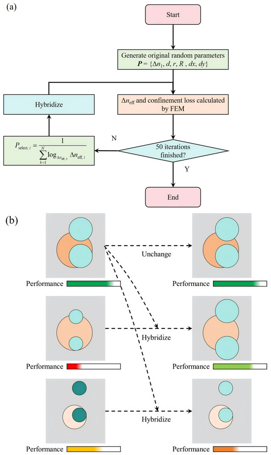
Figure 2.
Optimization of the proposed fiber structure using a genetic algorithm. (a) Flowchart of the optimization process; (b) schematic illustration of the crossover mechanism.
Through iterative selection, crossover, and mutation, the GA gradually refined the population, converging toward a configuration that maximized while maintaining low confinement loss. This automated approach thus replaced the conventional trial-and-error process with a systematic, data-driven optimization, significantly improving both design efficiency and performance robustness.
After evaluating all individuals in the current generation, the fitness values were normalized to derive the selection probability for each candidate. This probabilistic approach allows individuals with higher fitness to have a greater chance of being selected for reproduction while still maintaining population diversity through stochastic sampling. During the crossover operation, one parameter from a parent individual was randomly chosen and replaced by the corresponding parameter from another parent, which was selected according to the computed probability distribution. This mechanism enables efficient exchange of structural features between well-performing candidates, promoting the exploration of potentially superior parameter combinations. Similarly, during mutation, a single parameter in an individual was randomly reinitialized within its predefined bounds to introduce new genetic variation and prevent premature convergence to local optima. The elitist strategy was maintained throughout the process, ensuring that the best-performing individual from each generation was directly preserved in the next without modification, thereby guaranteeing monotonic improvement in the overall optimization performance.
Figure 3 illustrates the evolution of the minimum of the best individuals as the optimization progressed under different crossover probability and mutation probability . The results clearly show that appropriate combinations of these two parameters significantly influence the convergence rate and the achievable performance. After 30 generations, the minimum was successfully increased to under the setting of and , corresponding to the optimal parameter set . This result demonstrates the strong capability of the GA to effectively navigate the complex, high-dimensional design space and identify structures with enhanced modal separation.
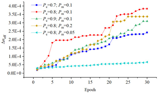
Figure 3.
Evolution of the minimum effective index difference of the best-performing individual across 30 generations during the optimization process.
Figure 4 presents the mode profiles and corresponding phase distributions of the ten guided polarization modes supported by the optimized fiber. Each eigenmode is clearly distinguishable by its distinct field localization pattern and phase periodicity, confirming the successful suppression of mode degeneracy and the preservation of high polarization purity. The orthogonality of the obtained vector modes further validates the structural symmetry and numerical stability of the optimized design.
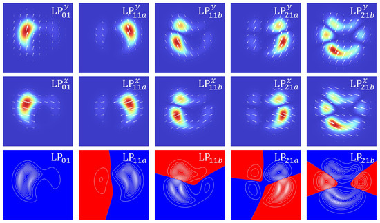
Figure 4.
Mode field distributions and phase profiles of the ten guided polarization modes supported by the optimized structure after 30 generations. Each mode is distinguished based on its spatial field pattern and phase periodicity.
In the following subsections, we analyze in detail the wavelength-dependent characteristics and structural robustness of the optimized fiber. These analyses provide a comprehensive understanding of the design’s performance across a broad spectral range and its tolerance to fabrication deviations, which are critical factors for practical implementation in space-division multiplexing systems.
3.3. Wavelength Characteristic
The wavelength-dependent effective refractive indices () and chromatic dispersion values of the supported modes were calculated using the FEM model described above. The results are presented in Figure 5 and Figure 6. To ensure numerical accuracy, the wavelength step size was set sufficiently small across the C+L band, and all calculations were carried out with adaptive mesh refinement until convergence of was achieved within a tolerance of . This procedure guarantees reliable evaluation of both modal dispersion and birefringence trends across the considered spectral range.
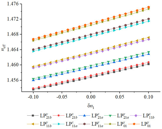
Figure 5.
Variation of minimum with the core index deviation for all guided modes in the optimized structure.
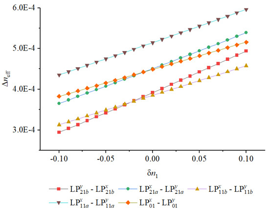
Figure 6.
Variation of effective refractive indices with the core index deviation .
As shown, the minimum occurs between the two orthogonally polarized components of the mode. Across the entire C+L band (1530–1625 nm), this separation remains consistently above , indicating excellent modal isolation and confirming that the optimized structure maintains strong birefringence even under broadband operation. Such a large effectively suppresses polarization coupling induced by external perturbations such as bending or thermal fluctuations, which is a critical condition for stable polarization-maintaining and MIMO-free transmission. This feature ensures that the individual vector modes can propagate independently over practical distances without requiring complex digital post-processing at the receiver.
Regarding the dispersion characteristics, the calculated chromatic dispersion curves reveal smooth spectral variation for all guided modes, suggesting good structural uniformity and low phase distortion. The maximum chromatic dispersion is observed in the mode, reaching up to . This moderate dispersion level provides a favorable trade-off between pulse broadening and inter-symbol interference. For short-reach or intra-data-center applications, such dispersion is beneficial because it limits temporal spreading while maintaining manageable compensation requirements, enabling high symbol rates with simplified system design.
Overall, the combination of high modal discrimination, stable birefringence, and moderate dispersion highlights the strong suitability of the proposed fiber for short-reach space-division multiplexing links. The robust polarization and mode isolation allow for fully MIMO-free operation, substantially reducing digital signal processing complexity and power consumption. These advantages are particularly significant in scenarios such as intra-data-center interconnects, high-performance computing environments, and optical backplanes, where cost, footprint, and energy efficiency are critical design constraints.
3.4. Tolerance Analysis
To evaluate the fabrication tolerance of the proposed fiber design, we investigate how deviations in key structural parameters affect the modal characteristics, particularly and the minimum among the ten modes. The analysis considers perturbations in both the high-index guiding core and the low-index symmetry-breaking inclusions, with relative variations ranging from to . The results are summarized in Figure 6, Figure 7, Figure 8 and Figure 9. All simulations were performed using the same FEM configuration as in the optimization stage to ensure consistent numerical accuracy and enable direct comparison between nominal and perturbed structures.
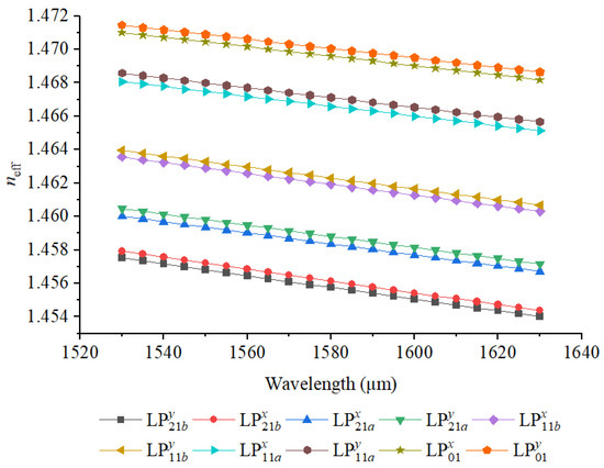
Figure 7.
Variation of effective refractive indices with wavelength for all guided modes in the optimized structure.
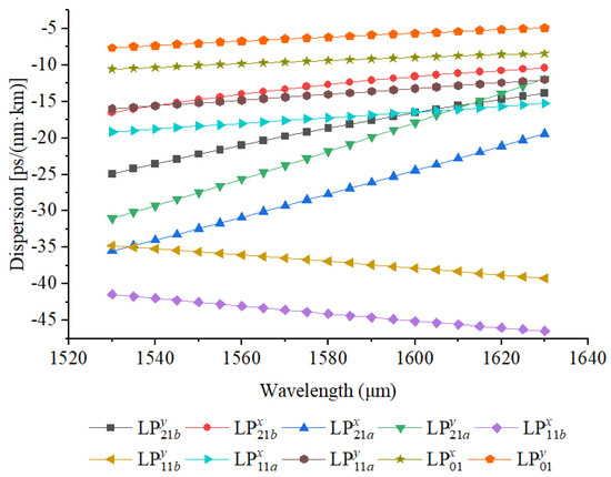
Figure 8.
Variation of dispersion with wavelength for all guided modes in the optimized structure.
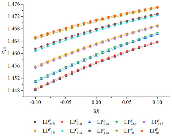
Figure 9.
Variation of minimum with core radius deviation for all guided modes in the optimized structure.
We first examine variations in the relative error in refractive index ratio () and radius (R) of the high-index core, denoted by and , respectively. As shown in Figure 6 and Figure 7, increasing results in higher values across all guided modes, which can be attributed to the stronger refractive index confinement and enhanced optical guiding capability. Conversely, reducing weakens the refractive index contrast, thereby diminishing modal confinement and reducing the effective separation between neighboring modes. In particular, at , the minimum drops to , with degeneracy observed between the two orthogonally polarized components of the mode. This trend highlights that small inaccuracies in doping concentration or refractive index control during preform fabrication can directly influence birefringence and inter-modal discrimination.
A similar behavior is observed when varying the core radius R, as depicted in Figure 9 and Figure 10. Increasing slightly elevates the overall values due to the enlarged core area and enhanced mode confinement. However, the minimum exhibits a gradual decline with increasing , reaching at . This degradation arises because larger cores reduce the strength of symmetry-breaking perturbations relative to the total guiding region, thereby allowing higher-order modes to overlap more strongly and approach degeneracy. The results imply that precise control of the core geometry, particularly the outer radius, is essential for maintaining high modal isolation in fabrication.
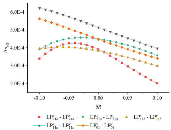
Figure 10.
Variation of effective refractive indices with the core radius deviation .
We further assess the influence of errors in the low-index perturbation structure that governs symmetry breaking. Figure 11 and Figure 12 illustrate the effect of refractive index ratio deviation in the fluorine-doped regions. Owing to the relatively weak field penetration into these low-index inclusions, remains nearly constant across the entire range, indicating that the design is intrinsically tolerant to variations in dopant concentration or fluorine diffusion. This robustness is advantageous from a manufacturing perspective, as it relaxes the material control requirements and allows for stable performance even with minor index fluctuations introduced during chemical vapor deposition or diffusion processes.
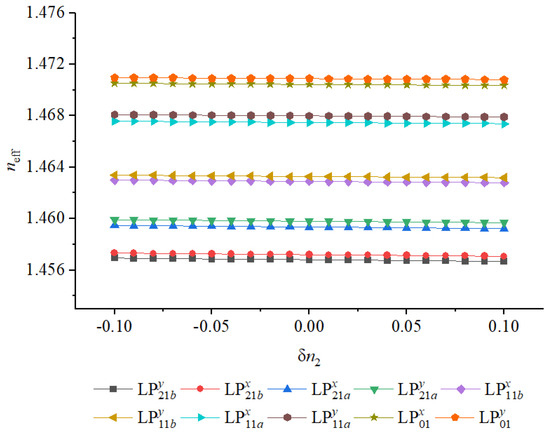
Figure 11.
Variation of minimum with low-index-region index deviation for all guided modes in the optimized structure.
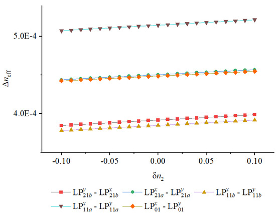
Figure 12.
Variation of effective refractive indices with low-index-region index deviation .
Overall, the analysis demonstrates that the proposed fiber structure maintains excellent modal stability under moderate fabrication perturbations. The modal separation remains well above across all tested variations, confirming that the optimized design offers sufficient fabrication tolerance for practical realization. Such stability is particularly valuable for large-scale production, where small parameter deviations are inevitable yet performance consistency is crucial for reliable system deployment.
In contrast, the influence of radial deviation of the low-index inclusions (Figure 13 and Figure 14) is considerably more pronounced. Since these fluorine-doped regions serve as critical geometric perturbations that lift mode degeneracy, even small variations in their dimensions can strongly alter the birefringence characteristics. The inclusions determine the local asymmetry of the refractive index distribution, thereby controlling the polarization splitting between otherwise degenerate higher-order modes. As decreases, the perturbation strength diminishes, leading to weaker coupling asymmetry and reduced birefringence. When , the minimum falls below the critical threshold required for effective polarization separation, which severely compromises the fiber’s polarization-maintaining capability.
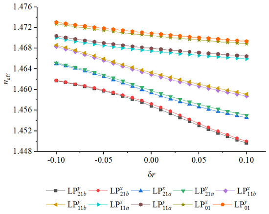
Figure 13.
Variation of minimum with low-index perturbation radius deviation for all guided modes in the optimized structure.
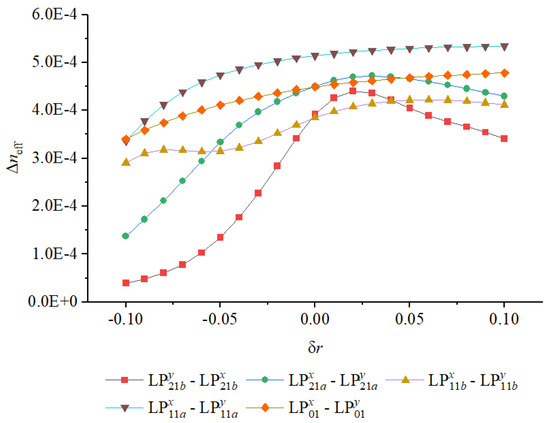
Figure 14.
Variation of effective refractive indices with low-index perturbation radius deviation .
On the other hand, increasing beyond the nominal value enhances the local refractive index contrast and slightly strengthens birefringence, but excessive enlargement may lead to overlapping or merging of the low-index regions, thereby distorting the intended field confinement pattern. This can result in localized perturbations of the mode field, introducing unwanted coupling among nearby modes and slightly increasing confinement loss. Hence, the effect of is not purely monotonic: while moderate positive deviations can improve polarization discrimination, larger deviations introduce optical and fabrication penalties.
These results indicate that precise control of the radial dimension of the low-index inclusions is essential during fabrication. The tolerance window for is narrower than that for or , implying that structural deviations in these regions play a dominant role in maintaining stable birefringence. From a practical standpoint, this sensitivity underscores the importance of high-precision preform drilling or modified chemical vapor deposition (MCVD) control to ensure uniform feature size and symmetry. The analysis confirms that maintaining within is sufficient to preserve high modal discrimination, ensuring reliable polarization-maintaining performance in mass-produced fibers.
To better contextualize the performance of the proposed fiber design within the state of the art, Table 2 provides a comprehensive comparison with several representative PM-FMF designs reported in the recent literature. The comparison highlights key performance metrics including the number of supported modes, minimum effective index difference, dispersion characteristics, and fabrication feasibility. This comparative framework emphasizes both the optical performance and the practicality of implementation, allowing a balanced assessment of the design trade-offs among different approaches.

Table 2.
Performance and structure comparison of representative PM-FMF designs.
Notably, the proposed design exhibits superior fabrication feasibility compared with the referenced structures. In particular, the formation of elliptical cladding structures—as employed in many conventional PM-FMF designs—poses significant challenges in maintaining precise geometric asymmetry throughout the drawing process. Achieving consistent elliptical profiles requires complex preform machining, fine control of surface tension during fiber pulling, and specialized pressure balancing techniques. These additional steps not only increase fabrication cost and complexity but also introduce higher risk of asymmetry loss and birefringence degradation during thermal processing. Consequently, yield and reproducibility often become limiting factors in large-scale production.
Ci et al.’s 10-hole configuration, though capable of achieving good modal discrimination, introduces additional complexity due to the presence of multiple air channels [26]. The maintenance of uniform hole size and spacing requires precise control over internal gas pressure during drawing, and minor deviations can lead to structural collapse or nonuniform stress distributions. In contrast, the proposed design eliminates both air holes and elliptical geometries entirely, relying instead on circular fluorine-doped silica inclusions that can be seamlessly incorporated during the rod-in-tube (RIT) preform fabrication process. This approach avoids the need for pressure-assisted hole preservation or asymmetric drawing control and is fully compatible with standard modified chemical vapor deposition (MCVD) techniques. The simplicity of the geometry not only improves fabrication reproducibility but also enhances structural stability during fiber drawing, ensuring consistent birefringence and mode separation.
Moreover, the use of isotropic, circular low-index regions reduces the dependence on directional deformation, yielding a polarization-maintaining structure that is inherently more tolerant to thermal or mechanical perturbations. When combined with the demonstrated high modal separation (>), the proposed fiber achieves a superior balance between optical performance and manufacturability, making it a practical candidate for space-division multiplexing systems that require MIMO-free operation with low signal crosstalk.
In summary, the proposed fiber design demonstrates strong robustness against refractive index variations and moderate dimensional tolerances, as validated through the fabrication tolerance analysis. Nevertheless, precise control over the core radius and the geometry of the symmetry-breaking inclusions remains essential to sustain large modal spacing and stable polarization diversity. These results confirm that the proposed structure can be readily fabricated using existing MCVD and RIT processes without the need for specialized equipment, offering both high performance and scalable manufacturability—key factors for real-world deployment in advanced optical communication systems.
4. Conclusions
A novel polarization-maintaining few-mode fiber structure has been proposed and optimized via a genetic algorithm to support ten well-separated spatial and polarization modes. By avoiding air holes and employing a uniformly doped structure with geometric perturbations, the design maintains compatibility with mature MCVD and OVD techniques. FEM-simulations verify a minimum above over the C+L band, along with moderate dispersion and strong modal confinement. Tolerance analysis shows that the structure is robust against refractive index variations and moderately tolerant to geometric deviations. These results demonstrate the feasibility of implementing high-performance PM-FMFs using simple and scalable fabrication approaches, with strong potential for enabling MIMO-free transmission in SDM systems.
Author Contributions
Software, H.G.; Formal analysis, J.W., Z.C., K.L. and X.H.; Resources, B.L. All authors have read and agreed to the published version of the manuscript.
Funding
This work was supported by the National Nature Science Foundation of China under Grant 62501542; the China Postdoctoral Science Foundation under Grant 2025M772901; the Fundamental Research Program of Shanxi Province under Grant 202303021222095; the Opening Foundation of Key Laboratory of Instrumentation Science & Dynamic Measurement, Ministry of Education, North University of China under Grant JYBSYSKFJJ319006; and the Foundation of State Key Laboratory of Extreme Environment Optoelectronic Dynamic Measurement Technology and Instrument under Grant 2024-SYSJJ-03.
Data Availability Statement
The raw data supporting the conclusions of this article will be made available by the authors on request.
Conflicts of Interest
The authors declare no conflicts of interest.
Abbreviations
The following abbreviations are used in this manuscript:
| CL | Confinement Loss |
| DSP | Digital Signal Processing |
| FEM | Finite Element Method |
| FMF | Few-Mode Fiber |
| GA | Genetic Algorithm |
| MCVD | Modified Chemical Vapor Deposition |
| OVD | Outside Vapor Deposition |
| MIMO | Multi-Input Multi-Output |
| SDM | Space-Division Multiplexing |
References
- Richardson, D.J.; Fini, J.M.; Nelson, L.E. Space-division multiplexing in optical fibres. Nat. Photonics 2013, 7, 354–362. [Google Scholar] [CrossRef]
- Nakajima, K.; Matsui, T.; Saito, K.; Sakamoto, T.; Araki, N. Space division multiplexing technology: Next generation optical communication strategy. In Proceedings of the 2016 ITU Kaleidoscope: ICTs for a Sustainable World (ITU WT), Bangkok, Thailand, 14–16 November 2016; pp. 1–7. [Google Scholar] [CrossRef]
- Downie, J.D.; Liang, X.; Makovejs, S. Assessing Capacity and Cost/Capacity of 4-Core Multicore Fibers Against Single Core Fibers in Submarine Cable Systems. J. Light. Technol. 2020, 38, 3015–3022. [Google Scholar] [CrossRef]
- Sillard, P. Few-mode fibers for space division multiplexing. In Proceedings of the 2016 Optical Fiber Communications Conference and Exhibition (OFC), Anaheim, CA, USA, 20–24 March 2016; p. Th1J-1. [Google Scholar]
- van den Hout, M.S.; Luís, R.; Puttnam, B.J.; Di Sciullo, G.; Hayashi, T.; Inoue, A.; Nagashima, T.; Gross, S.; Ross-Adams, A.; Withford, M.J.; et al. Reaching the pinnacle of high-capacity optical transmission using a standard cladding diameter coupled-core multi-core fiber. Nat. Commun. 2025, 16, 3833. [Google Scholar] [CrossRef] [PubMed]
- Oh, T.; Harjani, R. A 6-Gb/s MIMO Crosstalk Cancellation Scheme for High-Speed I/Os. IEEE J. Solid-State Circuits 2011, 46, 1843–1856. [Google Scholar] [CrossRef]
- Hu, D.; Cai, J.; Sun, L.; Xiong, J.; Ma, L.; Chen, B.; Cai, Y.; Liu, G.N. Mitigating the Strong Inter-Core Crosstalk during MCF Transmissions by Neural-Network-Equalizer-Based MIMO-DSP and Approaches for Its Simplification. Photonics 2024, 11, 196. [Google Scholar] [CrossRef]
- Xiong, Y.; Yang, Y.; Ye, Y.; Rouskas, G.N. A machine learning approach to mitigating fragmentation and crosstalk in space division multiplexing elastic optical networks. Opt. Fiber Technol. 2019, 50, 99–107. [Google Scholar] [CrossRef]
- Mercy Kingsta, R.; Shantha Selvakumari, R. A review on coupled and uncoupled multicore fibers for future ultra-high capacity optical communication. Optik 2019, 199, 163341. [Google Scholar] [CrossRef]
- Sakamoto, T.; Mori, T.; Wada, M.; Yamamoto, T.; Yamamoto, F.; Nakajima, K. Strongly-coupled multi-core fiber and its optical characteristics for MIMO transmission systems. Opt. Fiber Technol. 2017, 35, 8–18. [Google Scholar] [CrossRef]
- Inan, B.; Spinnler, B.; Ferreira, F.; van den Borne, D.; Lobato, A.; Adhikari, S.; Sleiffer, V.A.J.M.; Kuschnerov, M.; Hanik, N.; Jansen, S.L. DSP complexity of mode-division multiplexed receivers. Opt. Express 2012, 20, 10859–10869. [Google Scholar] [CrossRef] [PubMed]
- Qiao, G.; Long, C.; Yang, Y.; Xu, Z.; Zuo, M.; Wu, Q.; Wang, S.; Liu, L.; Shen, L.; Luo, J.; et al. Mode-division-multiplexing self-homodyne coherent transmission over a weakly coupled few-mode fiber for optical interconnections. Opt. Lett. 2024, 49, 981–984. [Google Scholar] [CrossRef] [PubMed]
- Yang, Y.; Qiao, G.; Ji, H.; Xu, Z.; Ji, T.; Wang, S.; Liu, L.; Zhu, B.; Long, C.; Zhang, J.; et al. 506-Pb/s·km C+L-Band 7-Core 2-Mode Transmission Over Weakly-Coupled FM-MCF with Only 2 × 2 MIMO. In Proceedings of the 2024 Asia Communications and Photonics Conference (ACP) and International Conference on Information Photonics and Optical Communications (IPOC), Beijing, China, 2–5 November 2024; pp. 1–4. [Google Scholar] [CrossRef]
- Zhao, J.; Tang, M.; Oh, K.; Feng, Z.; Zhao, C.; Liao, R.; Fu, S.; Shum, P.P.; Liu, D. Polarization-maintaining few mode fiber composed of a central circular-hole and an elliptical-ring core. Photonics Res. 2017, 5, 261–266. [Google Scholar] [CrossRef]
- Corsi, A.; Chang, J.H.; Wang, R.; Wang, L.; Rusch, L.A.; LaRochelle, S. Highly elliptical core fiber with stress-induced birefringence for mode multiplexing. Opt. Lett. 2020, 45, 2822–2825. [Google Scholar] [CrossRef] [PubMed]
- Song, W.; Chen, H.; Wang, J.; Liu, C.; Chen, Y.; Li, Z.; Liu, M. Panda type elliptical ring core few-mode fiber. Opt. Fiber Technol. 2020, 60, 102361. [Google Scholar] [CrossRef]
- Yan, H.; Li, S.; Xie, Z.; Zheng, X.; Zhang, H.; Zhou, B. Design of PANDA ring-core fiber with 10 polarization-maintaining modes. Photonics Res. 2017, 5, 1–5. [Google Scholar] [CrossRef]
- Xiao, H.; Li, H.; Jian, S. Hole-assisted polarization-maintaining few-mode fiber. Opt. Laser Technol. 2018, 107, 162–168. [Google Scholar] [CrossRef]
- Varner, W.F. Method for Making Shaped Highly Birefringent Optical Fibers. US Patent 6,580,860 B1, 17 June 2003. [Google Scholar]
- Varner, W.F. Method for Making W-Shaped Highly Birefringent Optical Fibers. US Patent 6,459,838 B1, 1 October 2002. [Google Scholar]
- Gu, Z.; Ning, T.; Pei, L.; Ye, X.; Hu, Z.; Li, J.; Guo, H.; Zheng, J.; Wang, J. Polarization-Maintaining Fiber with Uniform Doping Concentration Supporting 10 Weakly Coupled Modes Designed by Swarm Intelligence. IEEE J. Quantum Electron. 2025, 61, 6800309. [Google Scholar] [CrossRef]
- Debord, B.; Amrani, F.; Vincetti, L.; Gérôme, F.; Benabid, F. Hollow-Core Fiber Technology: The Rising of “Gas Photonics”. Fibers 2019, 7, 16. [Google Scholar] [CrossRef]
- Kato, K.; Takaoka, E. Sellmeier and thermo-optic dispersion formulas for KTP. Appl. Opt. 2002, 41, 5040–5044. [Google Scholar] [CrossRef] [PubMed]
- Yang, Z. Study on Few-Mode Fiber Dispersion Control, Characterization and Compensation. Ph.D. Thesis, Tianjin University, Tianjin, China, 2019. [Google Scholar]
- Zhang, J.; Chen, Y.; Wu, Z.; Feng, S.; Shum, P.; Huang, T. Panda type separated-circles-formed elliptical ring core few-mode fiber. Opt. Fiber Technol. 2022, 73, 103067. [Google Scholar] [CrossRef]
- Ci, Y.; Ren, F.; Lei, X.; Zhang, Y.; Wang, X.; Wang, J. A weakly-coupled air-hole-bow-tie-assisted few-mode fiber for short-haul MDM across C + L band. Opt. Quantum Electron. 2023, 55, 924. [Google Scholar] [CrossRef]
Disclaimer/Publisher’s Note: The statements, opinions and data contained in all publications are solely those of the individual author(s) and contributor(s) and not of MDPI and/or the editor(s). MDPI and/or the editor(s) disclaim responsibility for any injury to people or property resulting from any ideas, methods, instructions or products referred to in the content. |
© 2025 by the authors. Licensee MDPI, Basel, Switzerland. This article is an open access article distributed under the terms and conditions of the Creative Commons Attribution (CC BY) license (https://creativecommons.org/licenses/by/4.0/).


