Article

High-Precision Beam Deflection and Diagnostics System for EUV Synchrotron Radiation Illumination

1
Shanghai Synchrotron Radiation Facility, Shanghai Advanced Research Institute, Chinese Academy of Sciences, Shanghai 201210, China
2
Shanghai Institute of Applied Physics, Chinese Academy of Sciences, Shanghai 201204, China
3
Key Laboratory of Advanced Micro-Structured Materials MOE, Institute of Precision Optical Engineering (IPOE), School of Physics Science and Engineering, Tongji University, Shanghai 200092, China
*
Authors to whom correspondence should be addressed.
These authors contributed equally to this work.
Photonics 2025, 12(10), 970; https://doi.org/10.3390/photonics12100970 (registering DOI)
Submission received: 23 August 2025 / Revised: 12 September 2025 / Accepted: 26 September 2025 / Published: 30 September 2025

Abstract

The EUV light emitted by the synchrotron radiation source exhibits a stable wavelength and pollution-free characteristics, making it highly suitable for technical verification in diverse EUV lithography applications and playing a pivotal role in EUV lithography industry research. To guide the EUV light from the beamline into the experimental platform, this paper proposes a deflection system design based on the Shanghai Synchrotron Radiation Facility (SSRF). This system enables beamline diagnostics for EUV light while facilitating precise positioning and performance testing of the Mo/Si multilayer planar deflection mirror. The deflection system achieves accurate installation and alignment through a coordinate transfer protocol. By imaging the EUV incident light spot on a scintillator and analyzing variations in EUV light intensity data before and after the deflection mirror, the system can accurately measure focused light spot parameters from the beamline and achieve submicron alignment accuracy with 10 μrad angular resolution for the deflection mirror. The proposed design provides valuable insights for advancing EUV lithography technology utilizing synchrotron radiation sources.

1. Introduction

Extreme Ultraviolet (EUV) lithography has emerged as the dominant technology for manufacturing critical layers in advanced integrated circuits with process nodes below 7 nm and serves as a strategic cornerstone in modern semiconductor industry. Through decades of sustained research, the EUV scientific community has successfully addressed several fundamental challenges associated with this technology, particularly in achieving stable high-power EUV light sources to guarantee the reliability of exposure tools. Presently, EUV light generation is primarily accomplished through several major approaches: Laser-Produced Plasma (LPP) [1], Discharge-Produced Plasma (DPP) [2], High-Harmonic Generation (HHG) [3], synchrotron radiation sources [4] and Free-Electron Laser (FEL) [5]. Currently, commercially deployed LPP sources are predominantly utilized in EUV lithography systems [6], whereas DPP sources are employed in metrology tools for EUV mask inspection and review [7,8,9]. However, persistent mirror surface contamination caused by plasma-generated debris remains a critical challenge common to both approaches.
Synchrotron radiation-generated EUV light exhibits exceptional wavelength stability and contamination-free properties, positioning it as a critical enabler for next-generation EUV lithography demanding higher numerical apertures (NA) and shorter wavelengths (e.g., 6.7 nm). From the conceptualization of EUV lithography in the late 1980s to subsequent technological breakthroughs, synchrotron radiation sources have remained indispensable for validating fundamental EUV lithography technologies. Today, these sources continue to serve as vital research platforms in advancing EUV lithography industrialization [10,11,12]. Globally, leading synchrotron facilities have implemented advanced mask defect characterization technologies. For instance, a SHARP (semiconductor high-NA actinic reticle review project) system has been installed and commissioned at beamline 11.3.2 of the Advanced Light Source at Lawrence Berkeley National Laboratory in the United States, which performed actinic mask defect review [13]. And a 0.5-NA Extreme Ultraviolet micro-field exposure tool (MET) has also been installed and commissioned at beamline 12.0.1.4 to identify high-performing resists [14]. The beamline 10 at New SUBARU light source has built an EUV coherent scattering imaging station capable of both blank mask characterization and patterned mask defect inspection [15]. The beamline X09LB at Swiss Light Source developed RESCAN, a wavelength-specific imaging system utilizing coherent diffraction imaging for EUV mask metrology [16].
Compared to conventional LPP and DPP sources, compact synchrotron radiation sources based on small-scale accelerator architectures are increasingly recognized by the international research community as strategic EUV metrology platforms. For instance, the Paul Scherrer Institute (PSI) has pioneered a compact synchrotron concept aimed at enabling in-factory and laboratory-scale deployment of synchrotron-grade X-ray sources [17]. Pohang Accelerator Laboratory (PAL) has developed the PAL-EUV facility in an area of 15 m × 15 m or less, which is a compact-size EUV storage ring synchrotron facilities with sizes within tens of meters for use in the semiconductor industry [18]. These accelerator-driven EUV sources demonstrate three cardinal advantages: orders-of-magnitude higher brilliance, contamination-free emission characteristics, and superior wavelength tunability across the EUV spectrum. A critical research frontier lies in the effective integration of synchrotron-generated EUV radiation into lithographic process chains—particularly for actinic mask defect inspection and review systems—requiring innovative solutions in two key domains, design of high-efficiency illumination optics and implementation of robust EUV beam diagnostics [19,20]. This paper presents a comprehensive analysis of a high-precision EUV beam deflection system specifically engineered for synchrotron radiation applications. Through a coordinate transformation framework, the system achieves submicron alignment accuracy. Crucially, it enables real-time diagnostics of EUV beam profiles while facilitating precision characterization of Mo/Si multilayer deflection mirrors via actinic metrology.

2. EUV Beam Deflection System

Beamline 09B is an X-ray test beamline constructed during the second phase of the SSRF project. It was specifically designed to evaluate novel developments in optics and detector technology and to trial new experimental techniques. Operating in the 4–30 keV photon energy range, the beamline provides versatile beam modes [21]. In 2023, a new soft X-ray beamline was commissioned, covering 80–1000 eV with a monochromator resolving power exceeding 8000 [22].
A dedicated EUV beam deflection system was engineered and commissioned at the soft X-ray beamline to enable precise diagnostics of the incident EUV beam profile, as illustrated in Figure 1. The diagnostic assembly comprises five core subsystems: vacuum mirror chamber, vacuum system, scintillator, photodiode detector and imaging camera and so on. The vacuum mirror chamber is placed on a marble slab, with a multi-dimensional manual adjustment mechanism installed between the chamber and the marble, allowing for adjustment of the chamber’s height and attitude. The marble is positioned on a steel plate fixed to the floor using epoxy resin, making it easier to adjust the marble’s posture. These installation measures effectively isolate the chamber from high-frequency ground vibrations. The vacuum chamber is connected to the upstream beamline and downstream experimental station through flexible metal bellows. The vacuum level is regulated by a vacuum pump unit, which includes a mechanical pump and a molecular pump, and the vacuum level is displayed in real-time via a vacuum gauge. The vacuum mirror chamber contains two mirrors, scintillator, and photodetector, with an industrial camera imaging detector mounted on the outside. The details of the whole deflection system will be shown per functional system.

2.1. Deflection Planar Mirrors and Moving Stages

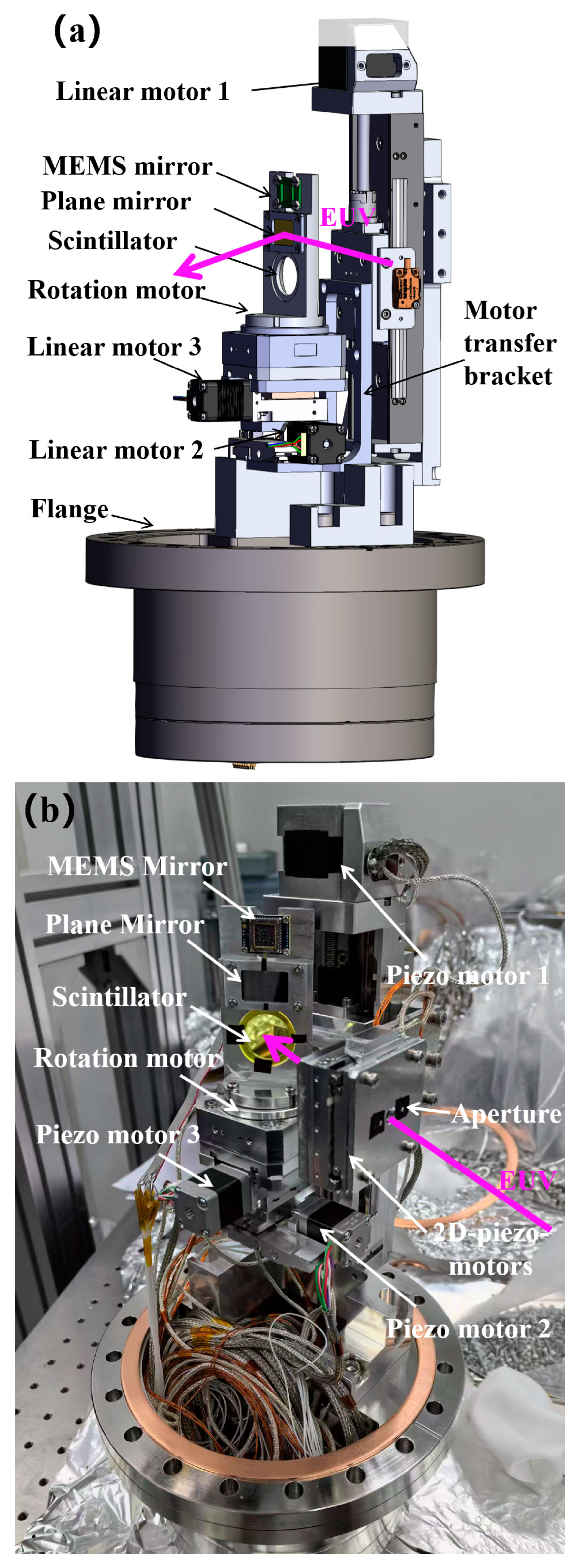
The internal structure of the beam deflection system is shown in Figure 2. The reflective mirrors serve as critical components within the deflection system, and are equipped with two mirrors featuring deposited Mo/Si multilayer coatings. The first is a large planar mirror with horizontal and vertical dimensions of 15 mm × 20 mm, designed to reflect the large-sized focused spots with low energy resolution (<1000). The second constitutes a micro-MEMS mirror [23] with a 2400 µm diameter and angle resolution of 10 μrad, functioning both as a reflector for the small-sized focused spots with high energy resolution (>5000) and as a Fourier synthesis illumination element to enhance the illumination NA through modulating coherent illumination parameters [24]. This setup can simulate the working environment of a lithography machine’s illumination system, playing a crucial role in supplying light to downstream lithography experimental platforms and mask imaging experimental platforms.
Both mirrors are mounted on four-dimensional motion stages equipped with three linear piezoelectric motors (labeled Motors 1, 2, and 3) for XYZ-axis control, plus a fourth rotary motor. Motors 1 and 2 provide 10 mm of travel range with 50 nm positioning resolution, while Motor 3 offers an extended 50 mm travel range while maintaining the same 50 nm resolution. The rotary stage achieves angular positioning precision of 0.001° (1/1000th of a degree). This configuration enables several critical functions: seamless switching between the two mirrors, precise adjustment of EUV beam incident angles on deflection plane mirrors, maintenance of the EUV spot position during mirror transitions, and adjust the numerical aperture and coherence of the reflected light.
The installation bracket must be machined with high precision to ensure co-planarity of the two mirrors. Given the presence of bracket processing errors and the operational constraints of laser tracker target-based contact positioning-particularly due to incompatibility with the deflection plane mirror’s micro-vibration-sensitive surface—a calibration protocol has been implemented using a visible light microscope. This system establishes three-dimensional coordinate parameters for the deflection plane mirror surface, mounting bracket interface, and rotational axis. To validate spatial relationships, contact measurements are subsequently performed using a coordinate measuring arm to quantify relative deviations. The derived positional coordinates of the deflection mirror are then spatially transferred to reference surfaces on the vacuum chamber’s external flanges. During final alignment, laser tracker metrology guides the vacuum chamber’s vertical positioning and angular orientation to achieve optimal coincidence (within specified tolerances) between the vacuum mirror chamber’s geometric center and the focal point of the upstream beamline. Post-installation verification ensures EUV spot position stability during mirror switching operations through closed-loop compensation of displacement stage coordinates in three-dimensional space.

2.2. Micro Aperture

The upstream beamline monochromatic light slit can regulate both the spot dimensions and spectral purity of the incident light reaching the deflection mirror. To enable finer optimization of critical parameters like the focal spot profile on the mirror surface, a vacuum-compatible two-dimensional piezoelectric linear stage with 20 mm travel range and 20 nm motion resolution has been integrated within the chamber. This precision positioning system incorporates an array of micron-scale apertures (20 μm, 50 μm, and 100 μm diameters) in a precisely configured geometric pattern as illustrated in Figure 2. The nanometer-scale alignment capability facilitates exact centering of selected apertures relative to the EUV beam axis. When synchronized with beamline slit adjustments, this dual-control architecture enables enhanced regulation of multiple performance metrics including focal spot dimensions, energy resolution (<0.1 eV achievable), and transverse coherence length at the deflection mirror plane.

2.3. YAG Scintillator and Imaging Camera

To accurately diagnose the position, size, and morphology of spots on the deflection mirror, a scintillator is used to convert EUV light into fluorescent radiation. To ensure sufficiently high conversion efficiency, the scintillator is fabricated from YAG: Ce-doped crystals. During installation, a measurement arm is employed to perform precise calibration and verify co-planarity between the scintillator and the mirror. Considering the influence of scintillator thickness on spot divergence, a 100-micrometer-thick YAG: Ce scintillator has been selected. In practical implementations, when the deflection mirror operates at oblique incidence angles, a circular scintillator with a 25 mm diameter is chosen to maintain full visibility of the EUV spot profile.
The EUV light spot on the YAG: Ce scintillator is imaged and observed using a Basler camera (model: acA2440-20gm). The camera features a 5 MP sensor with a chip resolution of 2448 × 2048 pixels (length × width) and a pixel size of 3.45 μm × 3.45 μm. A 35 mm focal length lens was employed to adjust the working distance, which was determined to be 260 mm. Based on calculations, the theoretical resolution of the system is 35.65 μm.

2.4. Photodiode Detector

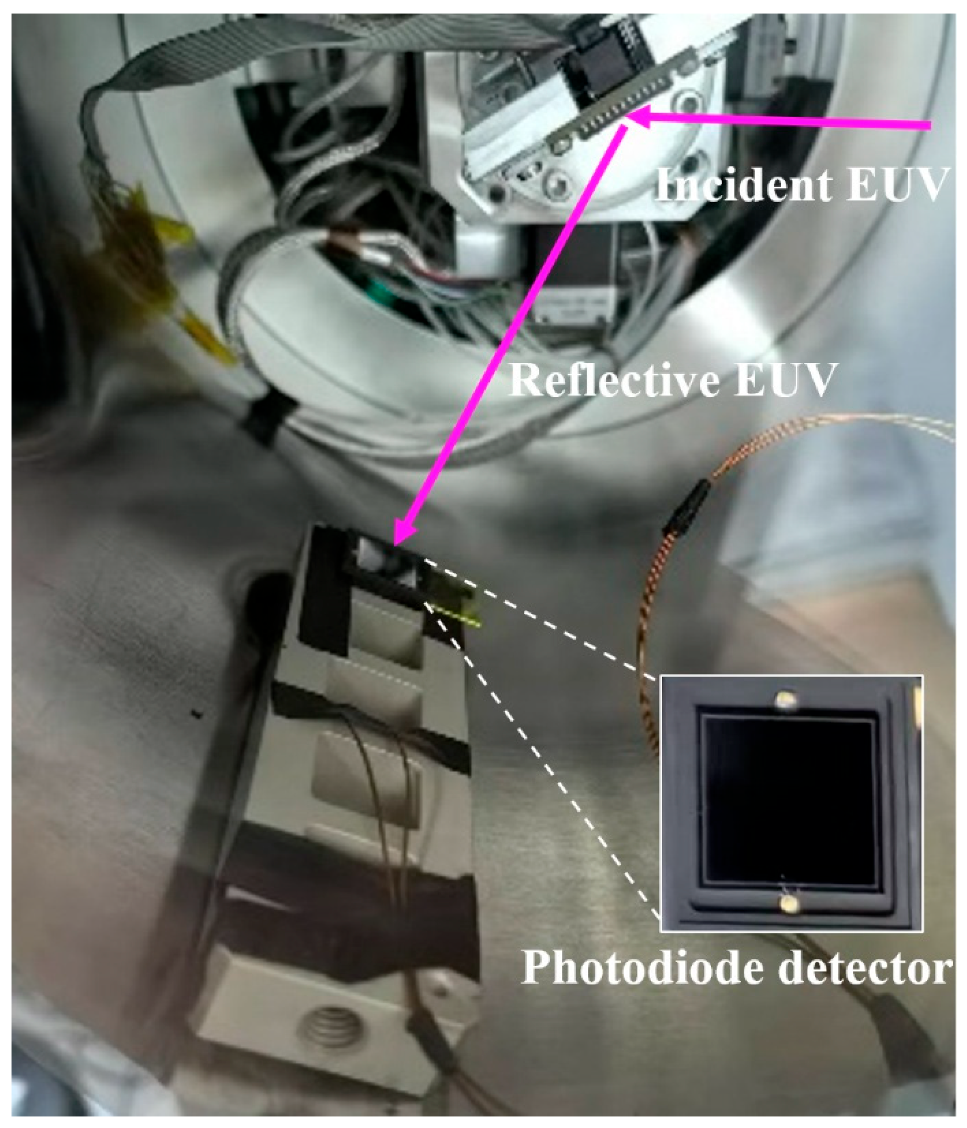
The incident EUV light flux is detected using photodiode (PD) detector. To quantitatively calibrate the light intensity before and after the deflection mirror and calculate its reflection efficiency, three PDs are positioned at strategic locations. The first is upstream of the vacuum chamber, the second is downstream of the vacuum chamber, and the last one is inside the vacuum chamber, as shown in Figure 3. All PDs are of the OPTO-AXUV100G model, with a 10 mm × 10 mm chip area. To accurately measure the reflected light flux at varying incident angles, the optimal PD configuration requires synchronized rotation around the deflection mirror’s axis. However, due to the operational constraints of the deflection mirror system, the PDs inside the vacuum chamber are fixed near the optimal reflection angle. During testing, the deflection mirror is translated along the beamline direction to expand the PD’s reception angle for the reflected light.

3. Experimental Results

3.1. Incident EUV Spot Imaging

After adjusting the orientation of all optical elements in the upstream beamline, the scintillator was moved into the optical path, and a Basler camera was used to capture fluorescence spot images. In the mechanical design, the scintillator and mirror are mounted on a four-dimensional motorized adjustment stage. During image acquisition, iterative optimization was performed to align the mirror near the theoretical best position in the incident light transmission direction and adjust the orientation of the upstream beamline’s focusing mirror. This ensured precise centering of the focused spot on the mirror. To determine the optimal focal position, the scintillator was translated along the upstream and downstream directions of the incident light while capturing a series of fluorescence spot images. The smallest spot location was subsequently identified through computational analysis.
The experimental results are presented in Figure 4. As visually depicted in Figure 4a, the focused spot is centered on the scintillator. Figure 4b displays the spot intensity profiles in both horizontal and vertical directions, with comparative analysis shown in Figure 4c. The spot dimensions in both directions exhibit near-identical magnitudes. The exact spot size was calculated using the full width at half maximum (FWHM) combined with the number of pixels covered by the spot and the theoretical pixel size. This quantitative approach enables precise determination of the spot dimensions.
To verify whether the central spot coincides with the mirror’s center, the positions of the scintillator spot must be recorded at varying mirror angles. As illustrated in Figure 4a, when the mirror rotates, the fluorescence spot center should remain stationary if the incident light is aligned with the mirror’s rotation axis. Subsequently, the mirror is inserted into the optical path, and positional variations of the spot on the downstream scintillator are analyzed.
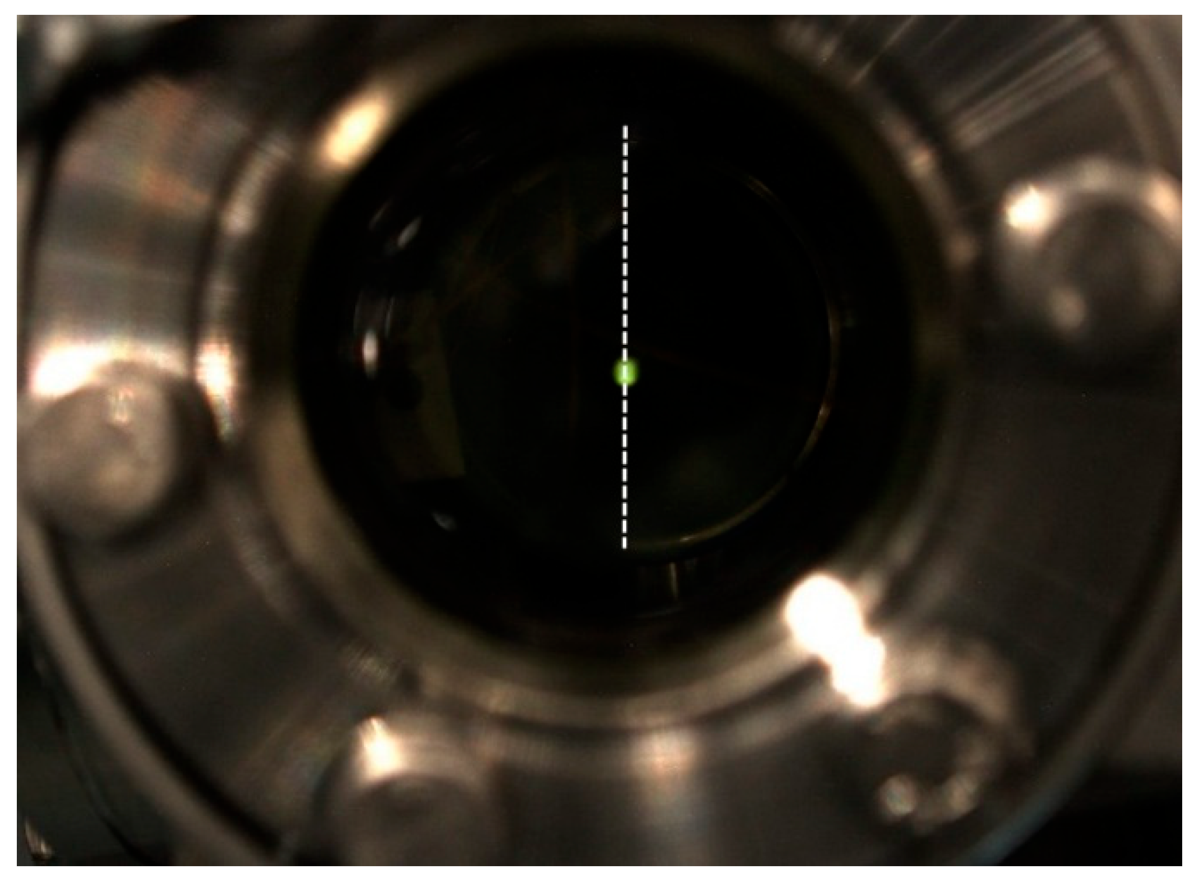
The scintillator, positioned at the PD location within the vacuum pipe (Figure 1), features etched horizontal and vertical stripe scales. Its installation was performed using a laser tracker to ensure sub-millimeter positioning accuracy. During mirror rotation and angular adjustments, the spot’s trajectory on the scintillator is observed to verify alignment with the vertical direction (Figure 5). By iteratively adjusting the mirror’s orientation based on the reflected spot’s trajectory—and confirming that the spot along the mirror’s axis remains stationary during rotation—the mirror’s installation posture can be precisely calibrated.

3.2. Mirror Reflection Efficiency

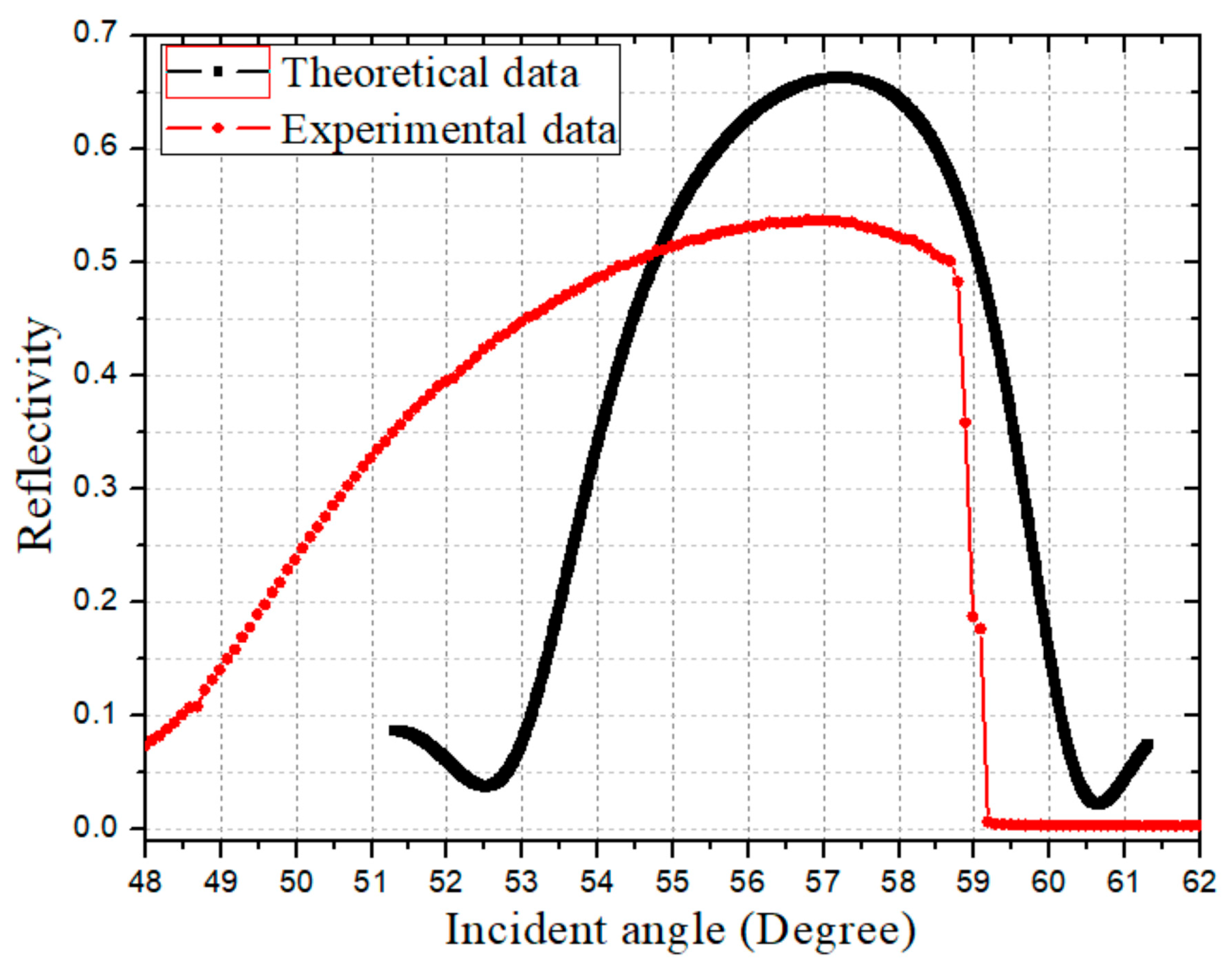
While the incident light spot’s position on the mirror can be accurately calibrated by observing its motion on the scintillator, precise angular positioning of the mirror requires reflectivity calculations. Both the large reflector and the small galvanometer in Figure 1 are optimized for an incident angle of 56.78°, which maximizes reflectivity. This is achieved through a Mo/Si multilayer coating with around 13.39 nm period [25], theoretically yielding 66.7% reflectivity at ~57° of s-polarized light, which is shown in Figure 6.
During measurements, the fixed position of the PD detector limited its angular reception range for reflected light from the mirror. To enhance the PD detector’s collection efficiency across varying reflection angles, the mirror was translated along the incident optical axis. Experimental data (red curve in Figure 6) reveal that due to the mirror’s limited axial translation range (10 mm) and obstruction by the mirror’s protruding clamp holder large-angle reflected light could not be captured by the PD detector. Laser tracker position calibration confirmed a maximum measured reflectivity of 53.75% at 56.78° incidence. Although this angle aligns with theoretical predictions, the actual reflectivity is lower than expected. Notably, the system maintains relatively high reflectivity over a wide angular range. This discrepancy originates from two contributing factors, one is elevated bandwidth of the incident light resulting from widening the monochromator exit slit to enhance flux, another is partial s-polarized light contamination in the incident beam. Despite these deviations, the measured reflectivity satisfies experimental requirements. Notably, the PD’s angular constraints prevented testing of lower reflection angles, as indicated by the truncated data in Figure 6.
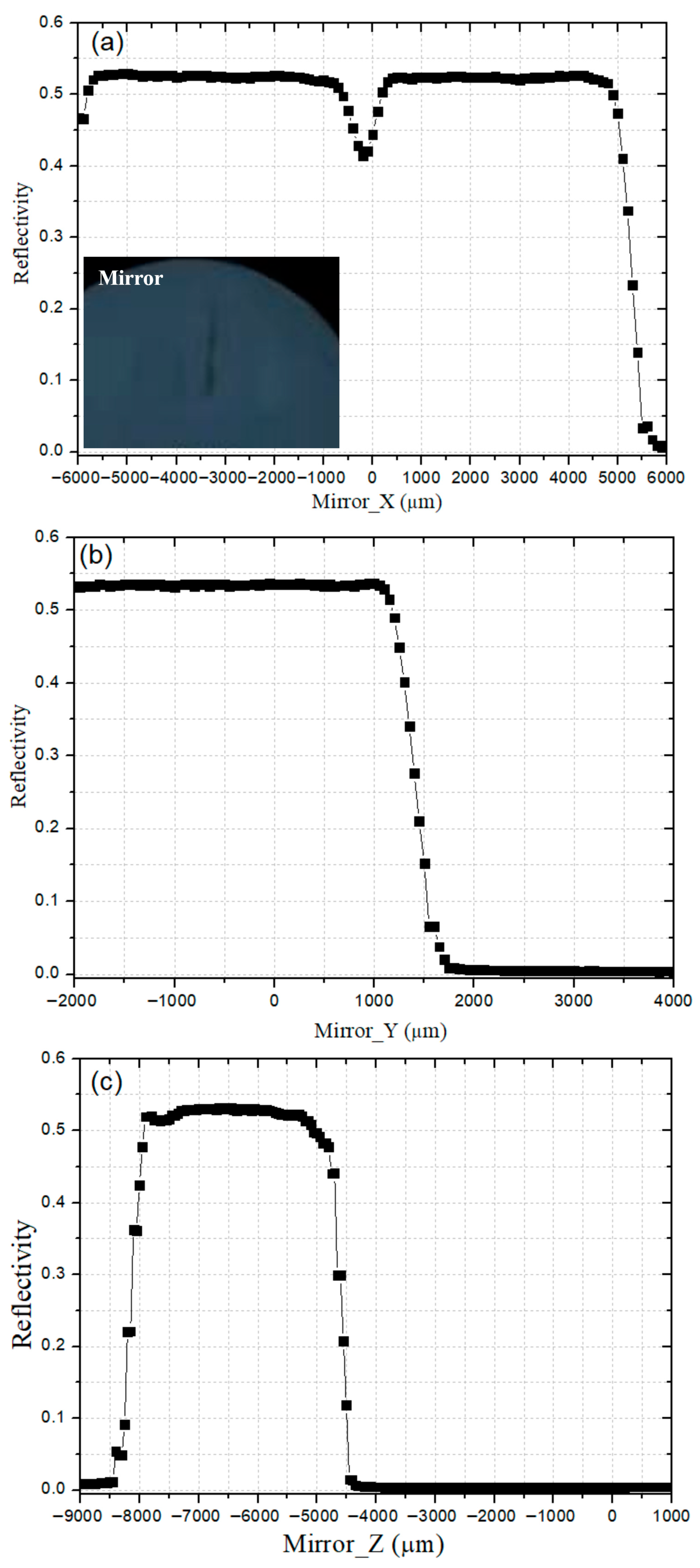
To calibrate whether the movement directions of each motor in the reflector assembly are horizontal and vertical, we adjusted the movement of each motor and collected PD intensity values after reflection. The values were plotted as functions of spatial coordinates. As shown in Figure 7, the X-direction (horizontal and perpendicular to the incident light direction) corresponds to the height adjustment motor shown in Figure 2. This motor has a 50 mm travel stroke and is used to switch different mirrors and scintillators into the optical path. The Y-direction (horizontal, parallel to the incident light) and Z-direction (vertical) both have 10 mm travel strokes.
Figure 7a demonstrates that when moving along the X-direction, the intensity deviation remains below 1.5% at both ends of the motor stroke. However, the central region shows reduced reflectivity caused by carbonization from long-term irradiation exposure. This observation confirms the high installation accuracy of the mirror. The relative deviations of reflected light intensity for Y- and Z-direction motor movements are 0.13% and 1%, respectively, indicating that both the alignment precision and positional accuracy of the reflector system meet required specifications.
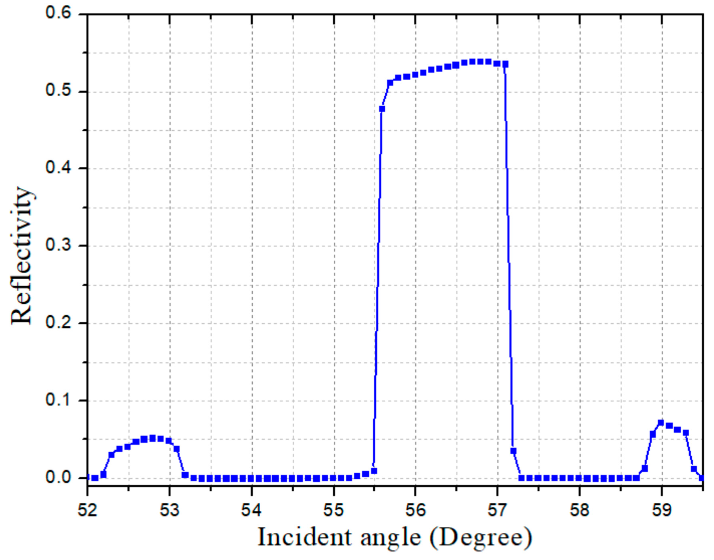
According to the specific requirements of downstream EUV micro-field exposure and EUV mask detection experimental platforms for EUV incident light characterization, it is necessary to investigate reflected light intensity variations when upstream-reflected beams traverse vacuum pipelines. Figure 8 displays the intensity curve corresponding to incident angle variations on the reflecting mirror during PD testing. Through comparison with Figure 6, the Mo/Si multilayer coating-configured with a center angle of 57° based on the reflector specifications-demonstrates consistent reflectivity characteristics near the central angle region. Notably, Figure 8 reveals slightly weaker secondary reflection signals appearing at specific angular positions flanking the primary reflection peak. Subsequent analysis identifies that downstream reflector positioning within the CF35 vacuum pipeline causes these anomalous signals: light reflected at extreme angles initially interacts with the pipe wall, undergoing partial reflection before being detected as attenuated signals by the PD detector. This phenomenon necessitates rigorous multi-stage verification protocols for precise mirror orientation calibration, ensuring measurement accuracy while mitigating positioning errors.

4. Discussion

A precision deflection system for EUV incident spot control was designed and implemented on Beamline 09B at SSRF. The system architecture integrates three core functions: (1) imaging the beamline’s focused spot using a scintillator-camera assembly, (2) directing the EUV beam from the beamline to downstream experimental stations via a deflection mirror, and (3) quantifying the reflected EUV intensity from the mirror using a PD detector. Through optimized mechanical design, seamless transition between scintillator-based imaging and mirror-based beam deflection is enabled, while precise mirror positioning within the vacuum chamber is achieved using a laser tracker and coordinate measurement arm.
By analyzing camera-captured EUV focal spot profiles and iteratively optimizing pre-/post-mirror reflection intensities, optimal beam alignment is attained through coordinated adjustments to both the beamline focusing mirror and deflection mirror orientations. Subsequent experimental validation, performed with a fixed central ray angle configuration on the deflection mirror, demonstrated robust system reliability through consistent EUV reflection data, confirming high-precision installation and alignment.
This deflection system’s design and implementation methodology offers a valuable framework for advancing synchrotron-based EUV lithography development and mask defect inspection platforms, particularly in applications requiring precise beam steering and stability.

Author Contributions

Conceptualization, H.L., B.Z. and X.Z.; Data curation, X.M. and J.Z.; Formal analysis, H.L.; Funding acquisition, H.L. and Y.W.; Investigation, Z.G.; Methodology, H.L.; Project administration, R.T.; Resources, X.Z. and Q.H.; Software, Z.Z.; Supervision, Y.W., Z.W. and R.T.; Validation, Z.G.; Visualization, H.L.; Writing—original draft, H.L.; Writing—review and editing, H.L. All authors have read and agreed to the published version of the manuscript.

Funding

This research was funded by National Natural Science Foundation (Grant nos. 12175297), the National Key Research and Development Program (Grant nos. 2022YFA1603703, 2021YFA1601000).

Institutional Review Board Statement

Not applicable.

Informed Consent Statement

Not applicable.

Data Availability Statement

For the system design and test results shown in figures, please contact liuhg@sari.ac.cn.

Conflicts of Interest

The authors declare no conflicts of interest.

Abbreviations

The following abbreviations are used in this manuscript:
SSRFShanghai Synchrotron Radiation Facility
EUVExtreme Ultraviolet
LPPLaser-Produced Plasma
DPPDischarge-Produced Plasma
HHGHigh-Harmonic Generation
FELFree-Electron Laser
NANumerical Apertures
METMicro-field Exposure Tool
PALPohang Accelerator Laboratory
PSIPaul Scherrer Institute

References

  1. Yang, D.-K.; Wang, D.; Huang, Q.-S.; Song, Y.; Wu, J.; Li, W.-X.; Wang, Z.-S.; Tang, X.-H.; Xu, H.-X.; Liu, S.; et al. The development of laser-produced plasma EUV light source. Chip 2022, 1, 100019. [Google Scholar] [CrossRef]
  2. Borisov, V.; Eltzov, A.; Ivanov, A.; Khristoforov, O.; Kirykhin, Y.; Vinokhodov, A.; Vodchits, V.; Mishhenko, V.; Prokofiev, A. Discharge produced plasma source for EUV lithography. Proc. SPIE Int. Soc. Opt. Eng. 2007, 6611, 79–86. [Google Scholar] [CrossRef]
  3. Bartels, R.A.; Paul, A.; Green, H.; Kapteyn, H.C.; Murnane, M.M.; Backus, S.; Christov, I.P.; Liu, Y.; Attwood, D.; Jacobsen, C. Generation of Spatially Coherent Light at Extreme Ultraviolet Wavelengths. Science 2002, 297, 376–378. [Google Scholar] [CrossRef] [PubMed]
  4. Ren-Zhong, T.; Yan-Qing, W.; Shu-Min, Y.; Lian-Sheng, W.; Jun, Z.; Chao-Fan, X.; Hai-Gang, L.; Zi-Jian, X. Developments at SSRF in soft X-ray interference lithography. Nucl. Sci. Tech. 2015, 26, 010101. [Google Scholar] [CrossRef]
  5. Kawata, H.; Nakamura, N.; Sakai, H.; Kato, R.; Hajima, R. High power light source for future extreme ultraviolet lithography based on energy-recovery linac free-electron laser. J. Micro/Nanopatterning Mater. Metrol. 2022, 21, 021210. [Google Scholar] [CrossRef]
  6. Abhari, R.; Rollinger, B.; Giovannini, A.; Morris, O.; Henderson, I.; Ellwi, S. Laser-produced plasma light source for extreme-ultraviolet lithography applications. J. Micro/Nanolithogr. MEMS MOEMS 2012, 11, 021114. [Google Scholar] [CrossRef]
  7. Kohyama, T.; Miyai, H.; Todoroki, T. Actinic Patterned Mask Inspection for EUV Lithography; SPIE: Bellingham, WA, USA, 2022; Volume 12325. [Google Scholar]
  8. Capelli, R.; Kersteen, G.; Krannich, S.; Koch, M.; Fischer, L.; Roesch, M.; Gwosch, K. Optical and EUV Nanolithography XXXV; SPIE: Bellingham, WA, USA, 2022; pp. 1205101–1205102. [Google Scholar]
  9. Rice, B.J.; Jindal, V.; Lin, C.C.; Harris-Jones, J.; Kwon, H.J.; Ma, H.C.; Goldstein, M.; Chan, Y.W.; Goodwin, F. Overview of Mask Metrology. AIP Conf. Proc. 2011, 1395, 281–289. [Google Scholar] [CrossRef]
  10. Xue, C.; Wu, Y.; Zhu, F.; Yang, S.; Liu, H.; Zhao, J.; Wang, L.; Tai, R. Development of broadband X-ray interference lithography large area exposure system. Rev. Sci. Instrum. 2016, 87, 043303. [Google Scholar] [CrossRef] [PubMed]
  11. Shiotani, H.; Suzuki, S.; Lee, D.G.; Naulleau, P.; Watanabe, T.; Fukushima, Y.; Ohnishi, R.; Kinoshita, H. Dual grating interferometric lithography for 22-nm node. In Proceedings of the 2007 Digest of Papers Microprocesses and Nanotechnology, Kyoto, Japan, 5–8 November 2007; pp. 46–47. [Google Scholar]
  12. Ekinci, Y.; Vockenhuber, M.; Hojeij, M.; Wang, L.; Mojarad, N. Evaluation of EUV resist performance with interference lithography towards 11 nm half-pitch and beyond. In Extreme Ultraviolet (EUV) Lithography IV; SPIE: Bellingham, WA, USA, 2013; Volume 8679, p. 867910. [Google Scholar]
  13. Goldberg, K.; Mochi, I.; Benk, M.; Allezy, A.; Dickinson, M.; Cork, C.; Zehm, D.; Macdougall, J.; Anderson, E.; Salmassi, F.; et al. Commissioning an EUV mask microscope for lithography generations reaching 8 nm. In Extreme Ultraviolet (EUV) Lithography IV; SPIE: Bellingham, WA, USA, 2013; Volume 8679. [Google Scholar]
  14. Anderson, C.; Allezy, A.; Chao, W.; Cork, C.; Cork, W.; Delano, R.; DePonte, J.; Dickinson, M.; Gaines, G.; Gamsby, J.; et al. Overview and Status of the 0.5-NA Micro-field Exposure Tool at Berkeley Lab. In Extreme Ultraviolet (EUV) Lithography X; SPIE: Bellingham, WA, USA, 2019; p. 1095708. [Google Scholar]
  15. Tanaka, Y.; Harada, T.; Amano, T.; Usui, Y.; Watanabe, T.; Kinoshita, H. Characterization of small phase defects using a micro-coherent extreme ultraviolet scatterometry microscope. Jpn. J. Appl. Phys. 2014, 53, 06JC03. [Google Scholar] [CrossRef]
  16. Mochi, I.; Helfenstein, P.; Mohacsi, I.; Rajendran, R.; Kazazis, D.; Yoshitake, S.; Ekinci, Y. RESCAN: An actinic lensless microscope for defect inspection of EUV reticles. J. Micro/Nanolithogr. MEMS MOEMS 2017, 16, 041003. [Google Scholar] [CrossRef]
  17. Bergmann, R.M.; Bieri, T.; Craievich, P.; Ekinci, Y.; Garvey, T.; Gough, C.; Negrazus, M.; Rivkin, L.; Rosenberg, C.; Schulz, L.; et al. A Compact Storage Ring for the Production of EUV Radiation. In Proceedings of the International Topical Meeting on Nuclear Applications of Particle Accelerators, Quebec City, QC, Canada, 31 July–4 August 2017. [Google Scholar]
  18. Ko, J.H.; Kim, M.W.; Lee, S.; Han, J.-H.; Hong, J. Strip-line injection kicker for PAL-EUV booster synchrotron. J. Korean Phys. Soc. 2024, 84, 189–197. [Google Scholar] [CrossRef]
  19. Schafers, F.; Bischoff, P.; Eggenstein, F.; Erko, A.; Gaupp, A.; Kunstner, S.; Mast, M.; Schmidt, J.-S.; Senf, F.; Siewert, F.; et al. The at-wavelength metrology facility for UV- and XUV-reflection and diffraction optics at BESSY-II. J. Synchrotron Radiat. 2016, 23, 67–77. [Google Scholar] [CrossRef] [PubMed]
  20. Miyakawa, R.; Naulleau, P. Preparing for the Next Generation of EUV Lithography at the Center for X-ray Optics. Synchrotron Radiat. News 2019, 32, 15–21. [Google Scholar] [CrossRef]
  21. Li, Z.; Fan, Y.; Xue, L.; Zhang, Z.; Wang, J. The design of the test beamline at SSRF. AIP Conf. Proc. 2019, 2054, 060040. [Google Scholar] [CrossRef]
  22. Xue, L.; Li, Z.; Liu, J.; Chen, H.; Zhao, G.; Wang, Y.; Zhu, W. Optical design and commissioning results of a constant-imaging-distance fixed-included-angle grating monochromator at SSRF. J. Synchrotron Radiat. 2025, 32, 605–608. [Google Scholar] [CrossRef] [PubMed]
  23. Milanović, V.; Kasturi, A.; Siu, N.; Radojičić, M.; Su, Y. “MEMSEYE” for optical 3D tracking and imaging applications. In Proceedings of the Transducers 2011 Conference, Beijing, China, 5–9 June 2011. [Google Scholar]
  24. Naulleau, P.P.; Goldberg, K.A.; Batson, P.; Bokor, J.; Denham, P.; Rekawa, S. Fourier-synthesis custom-coherence illuminator for extreme ultraviolet microfield lithography. Appl. Opt. 2003, 42, 820–826. [Google Scholar] [CrossRef] [PubMed]
  25. Montcalm, C.; Bajt, S.; Mirkarimi, P.B.; Spiller, E.A.; Weber, F.J.; Folta, J.A. Proceedings of SPIE; SPIE: Bellingham, WA, USA, 1998; pp. 42–51. [Google Scholar]
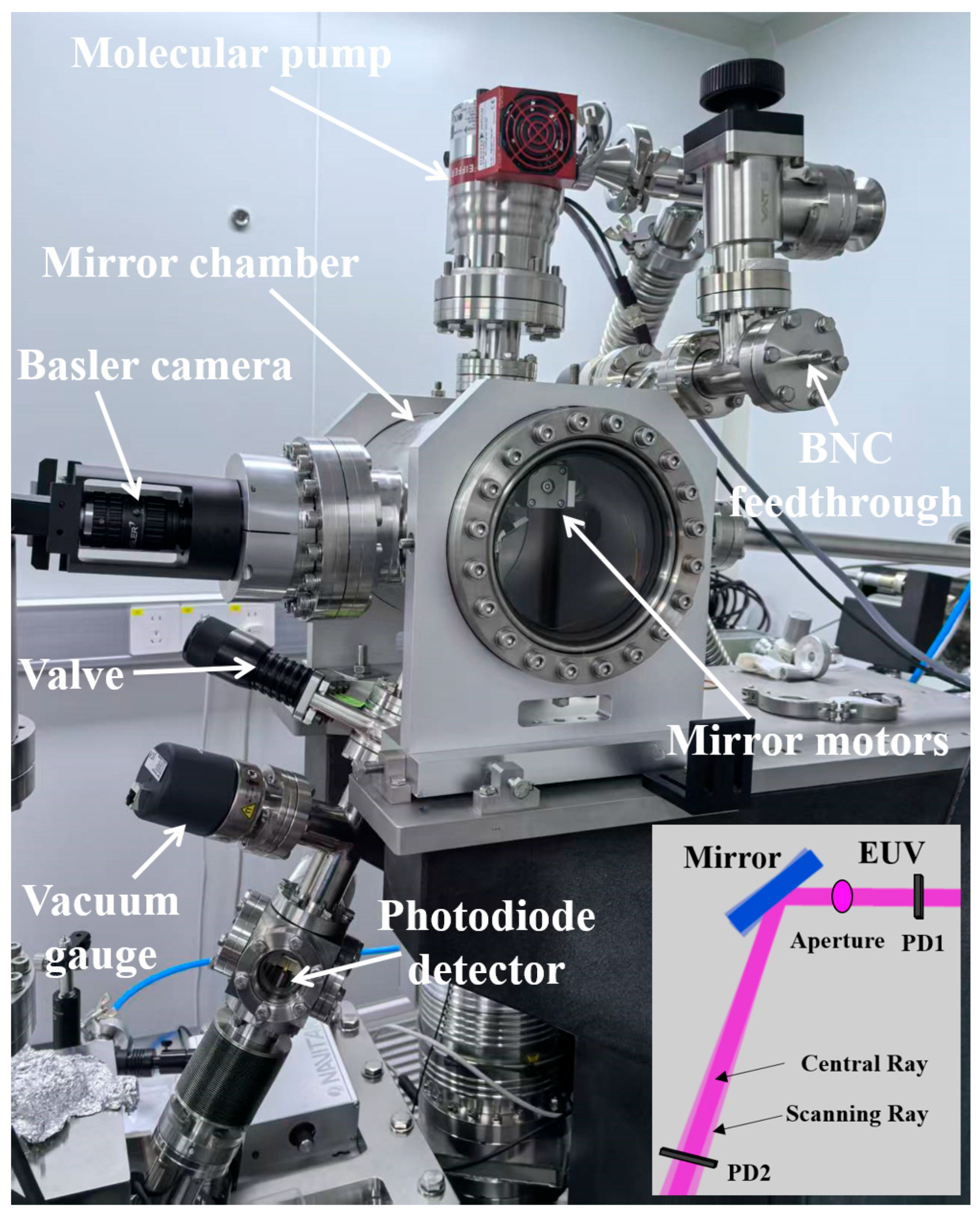
Figure 1. (Color online). Photograph of deflection system for EUV incident beam in the soft X-ray branching beamline of beamline 09B. The small image in the bottom right corner is a schematic diagram of optical path transmission, where PD is the photodiode detector.
Photonics 12 00970 g001
Figure 2. (Color online). Internal structure of the beam deflection system. (a) shows an engineering design drawing and (b) shows a photograph. Planar mirror, MEMS mirror, and a YAG: Ce scintillator are mounted on a 4-axis piezo-motor stage system, while micro-apertures are integrated on a 2-axis piezo-motor stage.
Photonics 12 00970 g002
Figure 3. (Color online) Photodiode detector integrated in the mirror chamber for EUV reflection intensity measurement.
Photonics 12 00970 g003
Figure 4. (Color online) EUV beam characterization via YAG: Ce scintillator imaging. (a) EUV focal spot image recorded by Basler camera. (b) Grayscale image of the EUV focal spot. (c) Cross-sectional distribution curve of the image in (b) along the horizontal and vertical directions.
Photonics 12 00970 g004
Figure 5. (Color online) Reflected EUV beam analysis via YAG: Ce scintillator imaging in PD detector configuration (see Figure 1).
Photonics 12 00970 g005
Figure 6. (Color online) Angle-dependent mirror reflectivity characteristics for theoretical and Experimental data.
Photonics 12 00970 g006
Figure 7. (Color online) Mirror alignment verification via reflectivity profiling. (a) Horizontal stage translation scan. (b) Beam-axis translation scan. (c) Vertical stage translation scan.
Photonics 12 00970 g007
Figure 8. (Color online). Angular dependence of deflected EUV radiation flux in beam steering system.
Photonics 12 00970 g008
Disclaimer/Publisher’s Note: The statements, opinions and data contained in all publications are solely those of the individual author(s) and contributor(s) and not of MDPI and/or the editor(s). MDPI and/or the editor(s) disclaim responsibility for any injury to people or property resulting from any ideas, methods, instructions or products referred to in the content.