Article

Switchable Dual-Comb Fiber Laser Based on Sagnac Loop for Wavelength-Multiplexing and Polarization-Multiplexing

Department of Electrical and Electronic Engineering, Southern University of Science and Technology, Shenzhen 518055, China
*
Author to whom correspondence should be addressed.
Photonics 2025, 12(10), 961; https://doi.org/10.3390/photonics12100961 (registering DOI)
Submission received: 17 August 2025 / Revised: 12 September 2025 / Accepted: 26 September 2025 / Published: 28 September 2025
(This article belongs to the Special Issue Advances in Solid-State Laser Technology and Applications)

Abstract

We present an all-fiber erbium-doped mode-locked laser capable of switching among continuously tunable single-pulse mode-locking, wavelength-multiplexing asynchronous-pulse mode-locking, and polarization-multiplexing asynchronous-pulse mode-locking states. The multiplexing mechanisms under different conditions are confirmed by separating the asynchronous-pulse sequences. Experimental results and numerical simulations indicate that the adjustment of the polarization controller within the Sagnac loop is the key factor for switching between wavelength- and polarization-multiplexing asynchronous-pulse mode-locking. The multiple output characteristics of the same laser can support diverse application scenarios, offering significant cost reduction in practical applications. To the best of our knowledge, this is the first demonstration of switching between wavelength- and polarization-multiplexing asynchronous-pulse mode-locking states in a noise-like laser. Compared to previous related work, the proposed laser not only enables tunable mode-locking wavelengths but also achieves higher pulse energy. This work provides a light source solution with a simple structure and high switchability for dual-comb applications.

1. Introduction

Optical frequency combs manifest as periodic trains of ultrashort pulses in the time domain, and as a series of narrow-linewidth spectral lines with equal frequency spacing, fixed positions, and broad spectral coverage in the frequency domain. Highly stable optical frequency combs are extensively applied in high-precision ranging [1], optical atomic clocks [2], and precision spectroscopy [3]. Conventional dual-comb systems usually require two independent lasers with phase locking or additional modulation techniques [4,5,6,7,8], which greatly increases the cost and complexity of the system. In recent years, researchers have introduced the concept of “multiplexing” into the field of fiber lasers, making single-cavity dual-comb mode-locked fiber lasers a new research focus. Such lasers can generate dual-comb pulse sequence from the same cavity through wavelength multiplexing [9,10,11,12,13], polarization multiplexing [14,15,16], and propagation-direction multiplexing [17], which not only suppresses common-mode noise but also significantly simplifies the structure of dual-comb systems.
Single-cavity dual-comb mode-locked fiber lasers based on different multiplexing mechanisms possess distinct advantages. For example, in wavelength multiplexing, light waves at different wavelengths propagate with different group velocities in the fiber, usually leading to a larger repetition rate difference, which is beneficial for achieving higher sampling rates in asynchronous optical sampling [18,19]. Meanwhile, the generated asynchronous pulse sequences can be conveniently separated using wavelength-division multiplexers (WDMs). In polarization multiplexing, the two pulse sequences have a smaller difference in central wavelength and exhibit higher spectral overlap, thereby avoiding the need for spectral broadening in dual-comb ranging [15]. However, under this multiplexing mechanism, the output pulse sequences are difficult to completely separate by polarization beam splitter (PBS). In directional multiplexing, the two pulse sequences propagate clockwise and counterclockwise in the laser cavity, allowing for automatic separation in laser outputs of different directions. Nevertheless, bidirectional propagation enhances gain competition within the cavity, resulting in reduced output stability.
In summary, if dual-pulse sequence outputs with different multiplexing schemes can be realized within the same laser cavity, they will provide more practical dual-comb light sources for diverse applications. In 2016, Wu et al. [20] first reported the coexistence of scalar and vector solitons in a fiber laser mode-locked based on the nonlinear polarization rotation (NPR) mechanism, demonstrating that two different types of nonlinear pulses can exist within the same laser cavity. In the same year, Wu et al. [21] achieved switchable generation of vector and scalar solitons in a fiber laser cavity by utilizing a saturable absorber and the residual polarization dependent loss (PDL) in a wavelength-division multiplexer (WDM). These works laid the theoretical foundation for subsequent generation of different types of dual-pulse sequences within a single laser cavity. In 2019, Li et al. [22] achieved both wavelength- and polarization-multiplexing asynchronous pulse mode-locking by tuning the erbium-doped fiber (EDF) gain peak in combination with intracavity birefringence. However, due to the fixed EDF gain peaks near 1530 nm and 1560 nm, wavelength tuning could not be achieved. In 2024, Jin et al. [23] demonstrated switchable wavelength- and polarization-multiplexing asynchronous pulse mode-locking in an EDF laser. However, the resulting asynchronous pulses exhibited relatively low pulse energies. Wavelength-multiplexing dual-comb generation mechanism relies on wavelength-selective devices, which often exhibit PDL that may interfere with polarization-multiplexing. The key for polarization-multiplexing is to maintain simultaneous oscillation of light in two orthogonal polarization directions. If there is PDL in the cavity, it may suppress the light in one polarization direction, thereby preventing the realization of polarization-multiplexing [23]. Therefore, coexistence of wavelength- and polarization-multiplexing within a single laser cavity remains highly challenging.
In this work, we present an erbium-doped mode-locked laser based on a Sagnac loop, which achieves tunable single-pulse mode-locking as well as wavelength- and polarization-multiplexing asynchronous pulse mode-locking through precise control of pump power and polarization controllers (PCs). To the best of our knowledge, this is the first demonstration of switching between wavelength-multiplexing and polarization-multiplexing asynchronous pulse mode-locking in a noise-like laser (NLL). The filtering transmission spectrum of the Sagnac loop exhibits a comb-like distribution and is tunable, which has led to its widespread application in dual-wavelength and multi-wavelength mode-locked fiber lasers in previous studies [9,24]. Experimental results demonstrate that a Sagnac loop-based fiber laser, through the polarization-maintaining fiber (PMF) within the loop, can achieve polarization-multiplexing asynchronous pulse mode-locking. Compared to previous related works, the proposed laser not only offers the advantage of wavelength tunability but also delivers higher pulse energy due to the generation of noise-like pulses (NLPs). Overall, this work provides a potential light source with a simple architecture and strong switching capability for dual-comb systems.

2. Experimental Setup and Principle

The architecture of the laser constructed in this work is shown in Figure 1a. The pump source is a laser diode operating at a center wavelength of 976 nm and a maximum output power of 400 mW. The pump source and the reflection-type packaged SESAM (BATOP, SAM-1550-17-1.5ps, Jena, Germany) are coupled into the cavity through a 980/1550 nm WDM, which is connected to the Sagnac loop via a 60 cm-long EDF (LIEKKI, Er110-4/125, Camas, WA, USA). A polarization controller (PC1) is used in the optical path to adjust the polarization state of the light wave before it enters the Sagnac loop. The Sagnac loop consists of a 50/50 optical coupler (OC1), a 45 cm-long PMF (Corning, PM 1550, Corning, NY, USA) with birefringence of ~3.9 × 10⁻⁴, another polarization controller (PC2), and a 10/90 optical coupler (OC2), where the 10/90 OC2 is responsible for outputting 10% of the cavity energy.
The EDF in the laser cavity has a dispersion parameter of ~−20 ps/nm/km at 1550 nm and an absorption coefficient of ~110 dB/m at 1530 nm. The dispersion parameters of the PMF and the single-mode fiber (SMF) at 1550 nm are ~16 ps/nm/km and ~18 ps/nm/km, respectively. The total cavity length of the laser is 12.65 m, and the calculated net cavity dispersion is approximately −0.23 ps2, indicating that the laser operates in the negative dispersion region. The output pulses of the laser were measured using an oscilloscope (RIGOL, DS6104, Suzhou, China) combined with a photodetector (Thorlabs DET08CFC/M, Newton, MA, USA). The optical spectrum and radio-frequency (RF) spectrum were recorded using an optical spectrum analyzer (YOKOGAWA, AQ6370B, Tokyo, Japan) and an RF analyzer (RIGOL, DSA815, Suzhou, China), respectively. The output pulse width was measured using an autocorrelator (FEMTOCHROME, FR-103XL, Berkeley, CA, USA).
When the light wave enters the Sagnac loop through the OC1, part of the light propagates clockwise while the other part propagates counterclockwise. In the propagation, the two beams accumulate a phase difference and recombine at the OC1, where interference occurs, thereby producing a filtering effect. When considering only the filtering effect of the Sagnac loop, its transmittance curve can be expressed as [25]:
T = sin θ cos ϕ 2 2 ,
where θ represents the polarization rotation angle controlled by the PC2, and ϕ = 2 π B L / λ represents the phase difference introduced by the PMF. Here, B is the birefringence of the PMF, and L is the length of the PMF. The free spectral range (FSR) of the transmission curve of the Sagnac loop is given by [9]:
  Δ λ = λ 2 / B L ,
when the PMF length L in the optical path is 45 cm, the calculated FSR of the transmission curve of the Sagnac loop at 1570 nm is 14.05 nm. According to this formula with a fixed B value, different PMF lengths produce different FSRs of the transmission curve.

3. Results and Discussion

3.1. Single Pulse Mode-Locking with Tunable Center Wavelength

When the pump power is set to 85 mW, the laser achieves stable single pulse mode-locking, with an output power of 0.63 mW. On this basis, by adjusting the PC2 within the Sagnac loop, the center wavelength of the single pulse sequence output can be continuously tuned from 1565.9 nm to 1578.1 nm. Adjusting the PC2 changes the polarization state of the light propagating in the fiber, thus introducing additional phase shift between the two counter-propagating light beams inside the Sagnac loop. As the two beams pass through the OC1 again, the interference condition changes accordingly, leading to a shift in the peak position of the transmission curve of the Sagnac loop. This mechanism enables continuous tuning of the center wavelength of the single pulse sequence output within a certain wavelength range.
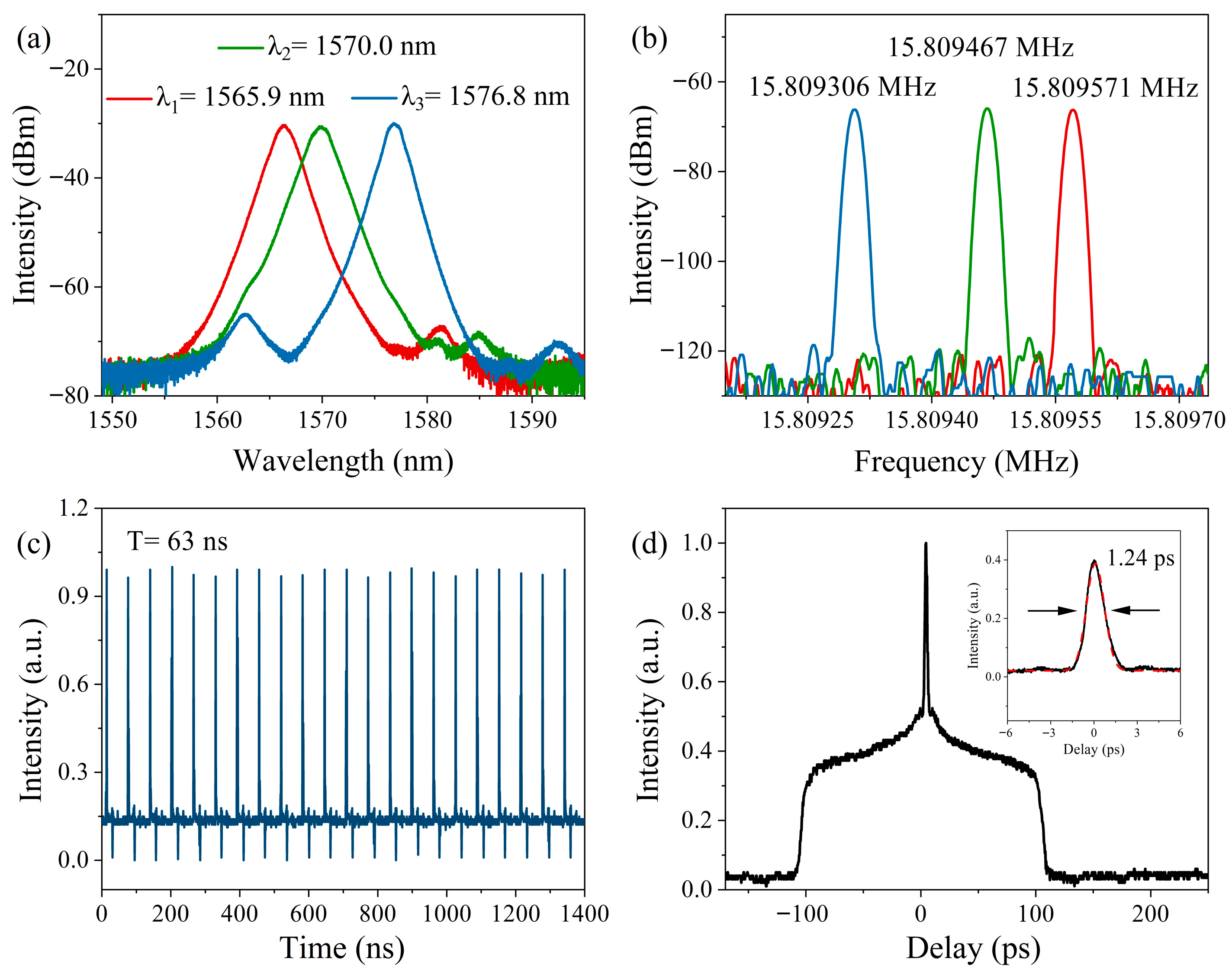
Figure 2 shows the output characteristics of single-pulse sequence at three representative wavelengths. As shown in Figure 2a, the center wavelengths of the typical optical spectra are at λ1 = 1565.9 nm, λ2 = 1570.0 nm, and λ3 = 1576.8 nm, with −3 dB bandwidths of 2.07 nm, 2.14 nm, and 1.70 nm, respectively. The −3 dB bandwidth represents the frequency range where the signal power is reduced to half of its maximum value, and a signal within this range is considered to have sufficient energy and intensity. Figure 2b presents the corresponding RF spectra of the typical optical spectra, where the repetition rates corresponding to λ1, λ2, and λ3 are 15.809571 MHz, 15.809467 MHz, and 15.809306 MHz, respectively. The length of the laser cavity in this work is 12.65 m. Based on the formula f = c / n L , it can be determined that the laser is operating in the mode-locking state of fundamental frequency. From Figure 2b, it can be observed that the repetition rate of the mode-locked pulses decreases as the center wavelength increases. This phenomenon is attributed to the laser operation in the negative dispersion regime, where the group velocity of the light with longer-wavelength is lower than that of the light with shorter-wavelength. Figure 2c,d show the corresponding pulse train and the autocorrelation trace when the center wavelength of the mode-locked pulses is at λ2. From Figure 2c, it can be seen that the pulse train has a period of 63 ns, corresponding to the time of a pulse propagating in the laser cavity for a round trip, indicating that it is mode-locked at the fundamental mode-locking frequency. The autocorrelation trace of the output pulses shown in Figure 2d features a narrow spike sitting on a picosecond-scale pedestal. The double-scale autocorrelation trace together with the smooth spectrum indicates that the output corresponds to NLPs. The width of the pedestal characterizes the duration of the NLP wave packet. In this state, as the pump power increases, the top of the pedestal gradually flattens, which can be attributed to the further broadening of the NLP wave packet such that more portions extend beyond the scanning range of the autocorrelator.
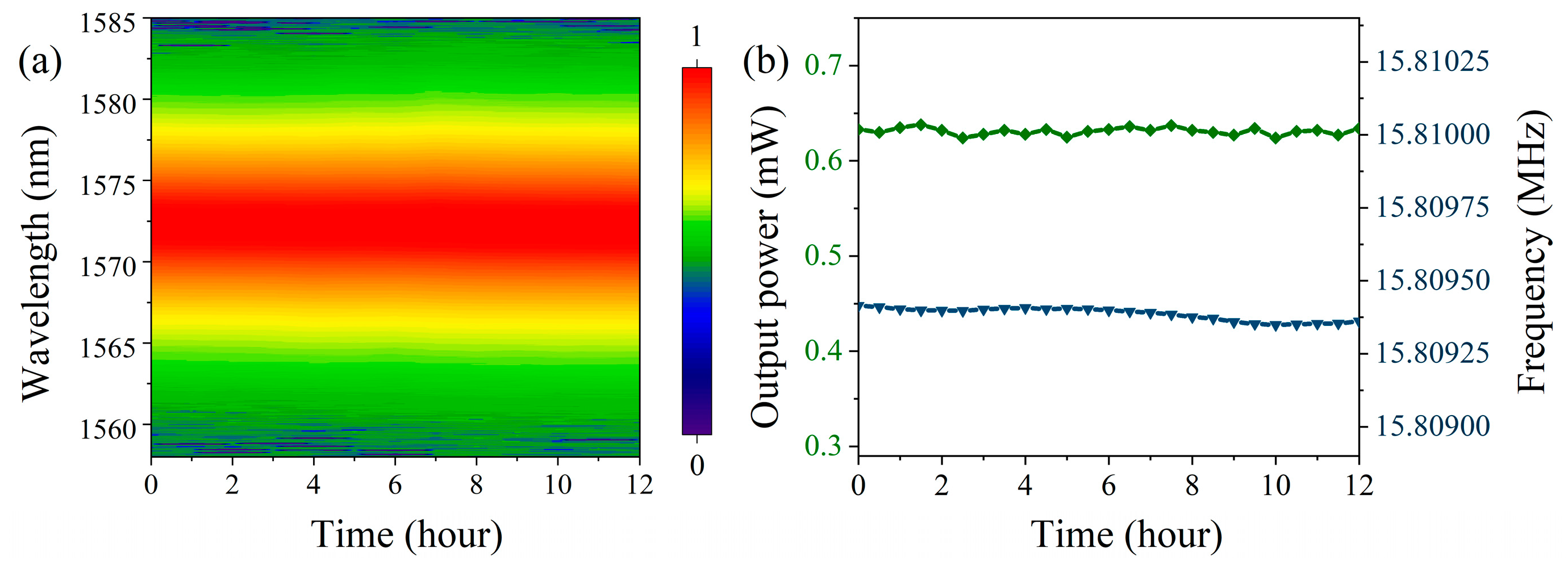
We further investigated the stability of the laser in the single-pulse mode-locked state. Figure 3 shows the variations in the laser’s spectrum, output power, and repetition rate during 12 h of continuous operation in this mode-locked state. As shown in Figure 3, the output spectrum and power of the laser remained essentially unchanged during the 12-h operation, demonstrating good stability. The maximum drift of the repetition rate during this period was 66 Hz, which we speculate is primarily caused by changes in the environmental temperature.

3.2. Asynchronous Pulse Sequence Generation with Wavelength-Multiplexing

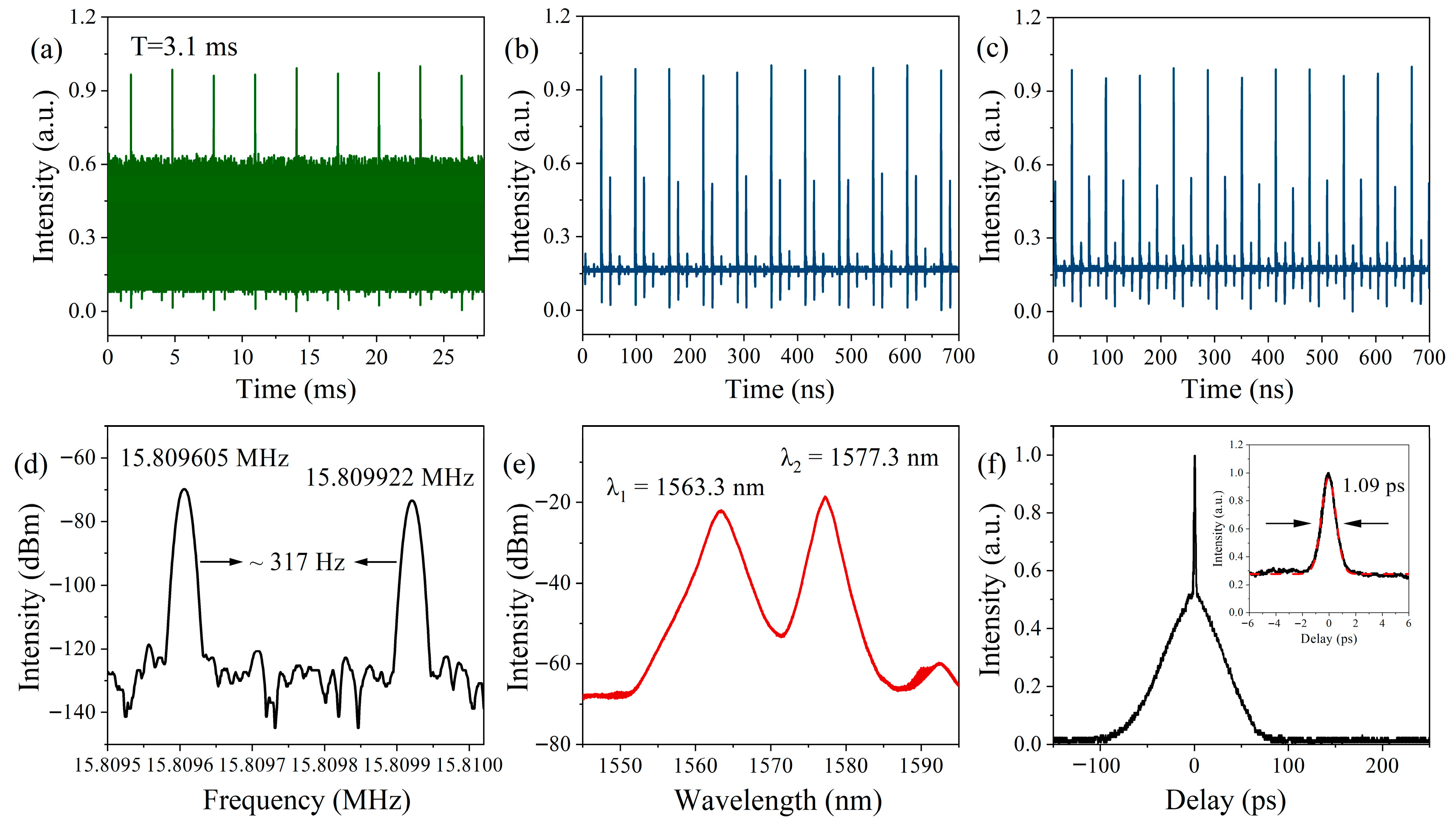
When the pump power is at 120 mW, the laser can achieve mode-locking with asynchronous pulse sequence generation, by carefully adjusting the PCs, and the mode-locking state can be maintained until the pump power is increased to 250 mW. Figure 4 shows output characteristics recorded with the pump power at 160 mW, where the output power is 1.40 mW. The pulse interference pattern with a period of 3.1 ms in Figure 4a indicates that the laser generates asynchronous pulse sequences. Setting the time window of the oscilloscope to 700 ns, two sets of pulse sequences with different amplitudes can be clearly observed. As shown in Figure 4b,c, the time intervals between the two sets of pulses vary at different moments, further demonstrating the asynchronous nature of the two pulse trains. Figure 4d,e show the RF spectra and optical spectra of the asynchronous pulse sequences, respectively. As shown in Figure 4d, the RF spectrum exhibits a distinct double-peak feature, with the peaks located at 15.809605 MHz and 15.809922 MHz, respectively, indicating a repetition rate difference of 317 Hz between the two pulse sequences. This frequency difference corresponds to the reciprocal of the pulse interference period shown in Figure 4a, with a slight deviation mainly due to the limited resolution of the RF analyzer. The optical spectrum shown in Figure 4e has two distinct center wavelengths, located at 1563.3 nm and 1577.3 nm, with −3 dB bandwidths of 2.3 nm and 1.5 nm, respectively. The wavelength separation between the two mode-locking centers is 14 nm, corresponding to the FSR of the transmission spectrum of the Sagnac loop. From the experimental observation presented above, it can be inferred that the mechanism of the asynchronous pulse sequence generation is based on wavelength-multiplexing with the Sagnac loop filtering effect. From the relationship between the center wavelength of the pulse sequence and repetition rate discussed in Section 3.1, it can be concluded that the pulse sequence with the center wavelength at λ1 has the repetition rate of 15.809922 MHz, while the pulse sequence with the center wavelength of λ2 has the repetition rate of 15.809605 MHz. Finally, the autocorrelation trace shown in Figure 4f indicates that the pulse is noise-like, and fitting with Gaussian yields a spike width of 1.09 ps.
We measured the stability of the laser in the wavelength-multiplexing asynchronous mode-locked state. Figure 5 shows the variations in the spectrum, output power, repetition rate, and repetition rate difference of the laser during 12 h of continuous operation in this mode-locked state. As shown in Figure 5a,b, the output spectrum and power exhibited no significant changes during the 12-h operation, demonstrating good stability. As illustrated in Figure 5c, the repetition rates of the two asynchronous pulse sequences each experienced a maximum drift of about 60 Hz; however, in the absence of any external modulation devices, the maximum drift of their repetition rate difference remained within 4 Hz. This result indicates that the inherent common-cavity effect of the single-cavity dual-comb system can effectively suppress the influence of environmental perturbations on the repetition rate difference between the two combs, thus providing important assurance for the stability and reliability of dual-comb light sources.
To further confirm that the asynchronous pulse sequences were generated via wavelength-multiplexing, we connected a coarse wavelength-division multiplexer (CWDM) at the laser output, as shown in Figure 1b. The CWDM has three ports: the COM input port, the transmission output port (1539–1565 nm), and the reflection output port (1575–1620 nm). After separation by the CWDM, the powers at the two output ports are 0.75 mW and 0.49 mW, respectively.
As shown in Figure 6a, the green curve represents the optical spectrum measured from the transmission port of the CWDM while the blue curve shows the optical spectrum measured from the reflection port of the CWDM. After passing through the CWDM, the two pulse sequences are basically separated. The slight overlap of the two spectra is due to the insufficient isolation between the two output ports of the CWDM. Figure 6b shows the RF spectra measured from the two output ports of the CWDM. From the RF spectrum, it can be seen that the pulse sequence with the center wavelength of λ2 is completely filtered out at the transmission output port, while a portion of the pulse sequence with the center wavelength of λ1 still remains at the reflection output port. At the reflection port, the signal-to-noise ratio (SNR) of the pulse sequence with the center wavelength of λ2 is significantly higher than that of λ1, with an SNR difference of more than 30 dB. Therefore, the pulse sequence with the higher repetition rate from the reflection output can be regarded as noise. Figure 6c and Figure 6d show the pulse sequences measured from the transmission and reflection output ports of the CWDM, respectively. As illustrated, the asynchronous pulse sequences generated in the laser cavity can be successfully separated with the CWDM, further confirming that the generation of the asynchronous pulse sequences is wavelength-multiplexing based. Specifically, this is accomplished by leveraging the interference effect of the Sagnac loop to create varying transmissivity for light waves of different wavelengths, thereby forming a filtering effect and realizing wavelength-multiplexing generation of the asynchronous pulse sequences.

3.3. Asynchronous Pulse Sequence Generation with Polarization-Multiplexing

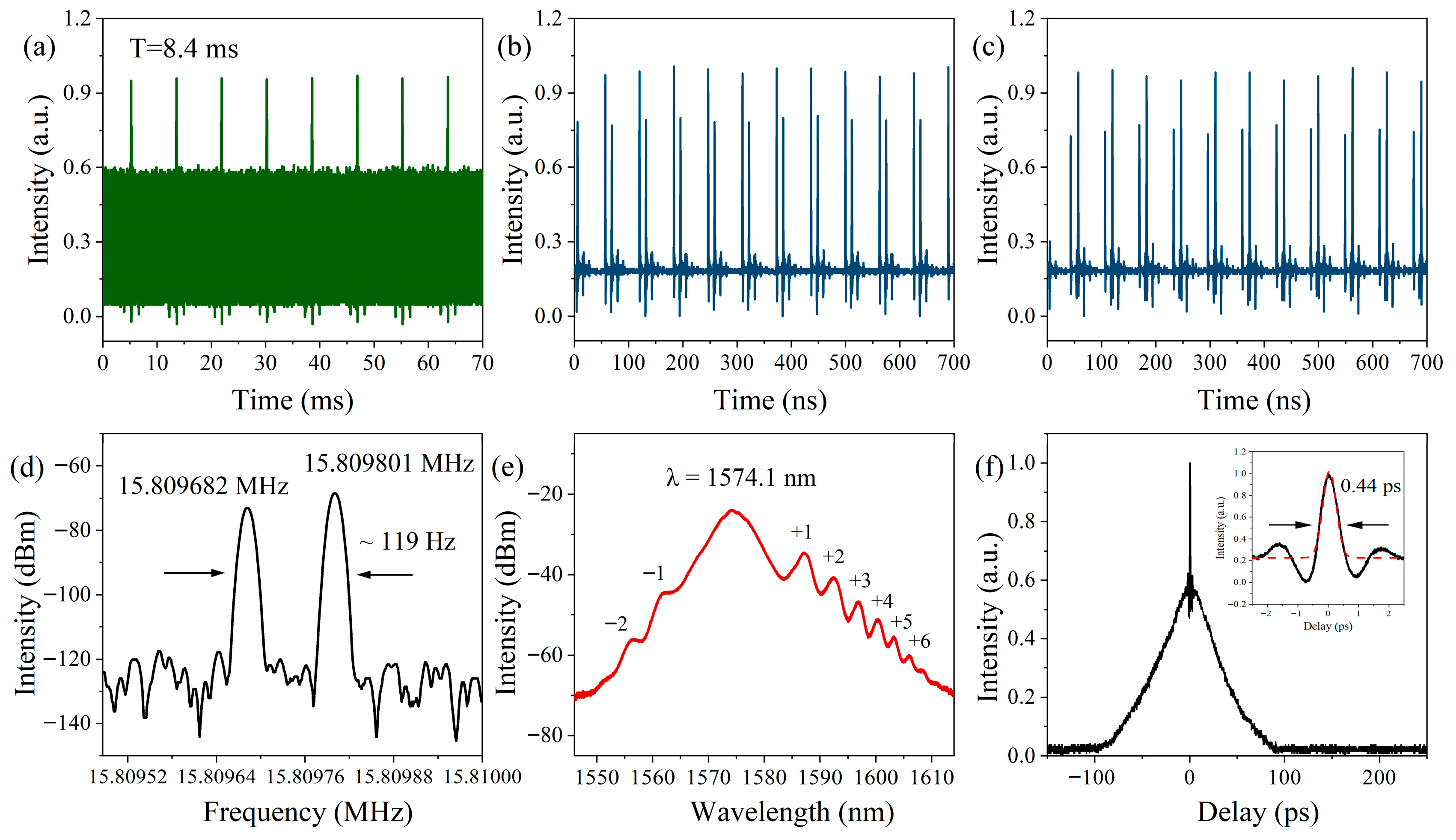
When the pump power is set to 190 mW, a pulse interference pattern with a larger fringe spacing than before is observed during the adjustment of the PCs. At this point, the output power of the laser is 1.72 mW. As shown in Figure 7a, the pulse interference period now is 8.4 ms. Together with the two sets of pulse sequences observed at different moments shown in Figure 7b,c, the results indicate that the laser now generates asynchronous pulse sequences with a different repetition rate difference than before. From the RF spectrum in Figure 7d, the repetition rates of the two pulse sequences in this state are determined to be 15.809628 MHz and 15.809801 MHz, respectively, corresponding to a repetition rate difference of 119 Hz, which is significantly smaller than the previous value of 317 Hz. Figure 7e displays the optical spectrum of the laser output with the center wavelength of 1574.1 nm and the −3 dB bandwidth of 5.3 nm. The optical spectrum exhibits a pronounced feature of the asymmetric sidebands, a phenomenon commonly observed in single-wavelength mode-locked pulse sequences in previous studies [26,27,28,29]. Our experiments demonstrate that the phenomenon of asymmetric spectral sidebands can also appear in asynchronous pulse sequences. Based on the spectral characteristics, it is inferred that the generation of asynchronous pulse sequences has transitioned from wavelength-multiplexing to other mechanisms. The autocorrelation trace in Figure 7f indicates that the pulse sequence in this state still consists of NLPs.
We measured the stability of the laser in the polarization-multiplexing asynchronous mode-locked state. Figure 8 shows the variations in the spectrum, output power, and repetition rate of the laser during 12 h of continuous operation in this mode-locked state. As shown in Figure 8a,b, the output spectrum and power exhibited no significant changes during the 12-h operation, demonstrating good stability. As illustrated in Figure 8c, the repetition rates of the two asynchronous pulse sequences each experienced a maximum drift of about 74 Hz; however, the maximum drift of their repetition rate difference remained within 4 Hz, indicating that the single-cavity dual-comb system can effectively suppress the influence of environmental perturbations on the repetition rate difference between the two combs.
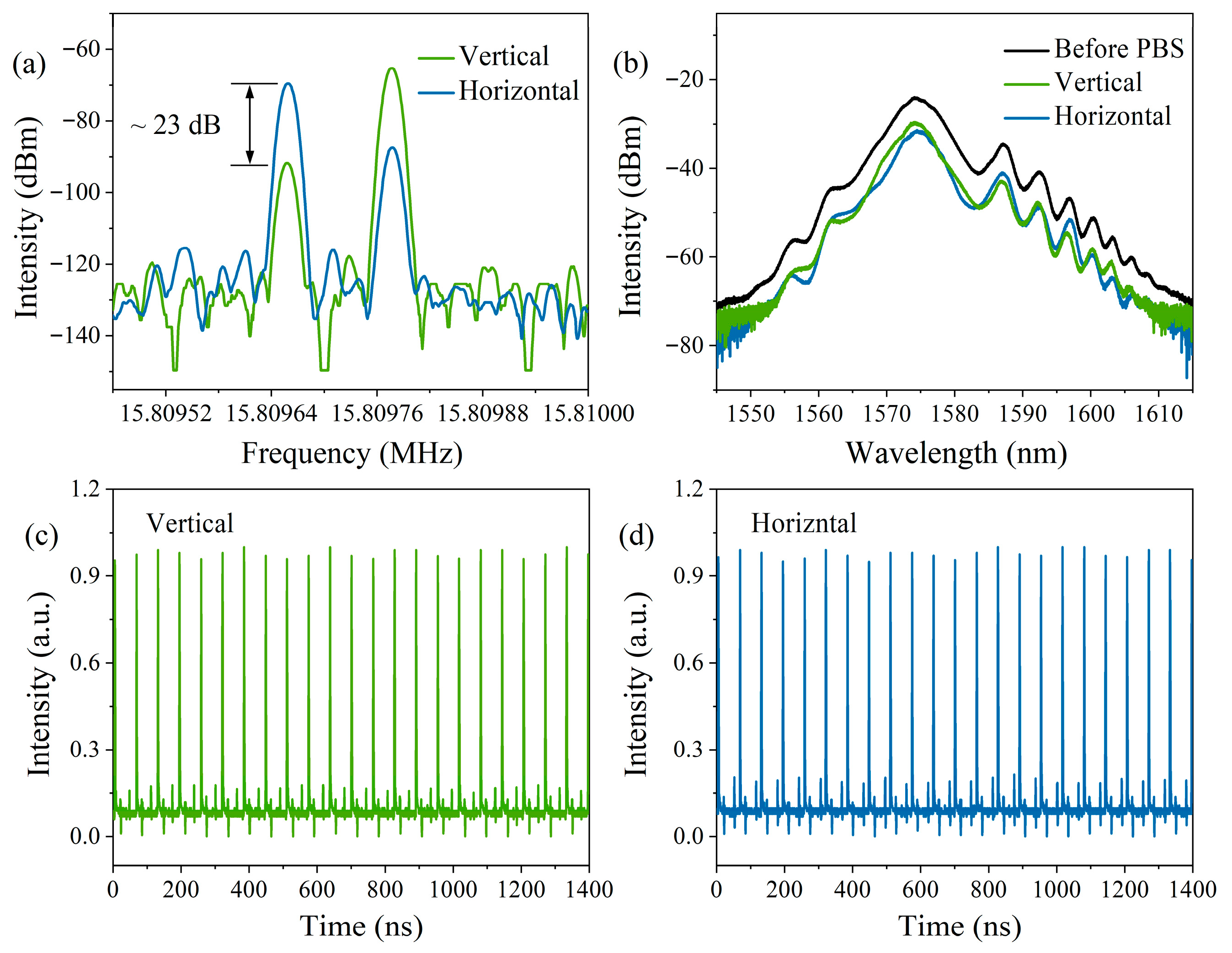
To elucidate the generation mechanism of the asynchronous pulse sequences, as shown in Figure 1c, a three-paddle polarization controller (3-paddle PC) and a PBS were connected to the laser output. By adjusting the 3-paddle PC placed before the PBS, the RF signal at the low repetition rate from the horizontal output port of the PBS was maximized. At this point, the optical powers at the vertical and horizontal output ports of the PBS were measured to be 0.76 mW and 0.69 mW, respectively.
The RF spectrum after PBS separation is shown in Figure 9a. In Figure 9a, the polarization extinction ratio of the two pulses is approximately 23 dB, indicating that the two pulse sequences are nearly orthogonally polarized to each other. This confirms that the generation of the asynchronous pulse sequences in the laser now is due to polarization-multiplexing [14,16]. Figure 9b shows the optical spectra of the pulse sequences after the PBS. As illustrated, the spectra measured from the vertical and horizontal polarization ports of the PBS exhibit similar shapes, with center wavelengths of 1573.9 nm and 1574.6 nm, respectively. Figure 9c,d show the pulse sequences measured with oscilloscope from the vertical and horizontal polarization ports of the PBS, respectively. Different from the pulse sequences separated by the CWDM with wavelength-multiplexing, a small amount of the other set of pulse sequences is still visible in the separated pulse sequences. This is because the two pulse sequences are not completely orthogonally polarized. The birefringence of the PMF inside the laser cavity leads to different refractive indices along different polarization directions. Combined with the meticulous adjustment of the PCs, this induces two sets of pulse sequences with distinct repetition rates in the orthogonal directions, which fundamentally explains the phenomenon of asynchronous pulse sequence output at this time.

3.4. Switching Between Wavelength-Multiplexing and Polarization-Multiplexing

3.4.1. Experimental Analysis

To investigate the key factor for switching between the two multiplexing mechanisms, we first studied the effect of pump power on the laser in the two mode-locked states. As shown in Figure 10a, in the wavelength-multiplexing mode-locked state, changing only the pump power from 120 to 200 mW led to an increase in spectral intensity, while the spectral shape remained essentially unchanged and the asynchronous mode-locking was maintained throughout. Similarly, in the polarization-multiplexing mode-locked state shown in Figure 10b, changing only the pump power from 130 to 250 mW also increased the spectral intensity without significantly altering the spectral shape, and the asynchronous mode-locking was preserved. These results indicate that variations in pump power are not the key factor for switching between the two multiplexing mechanisms.
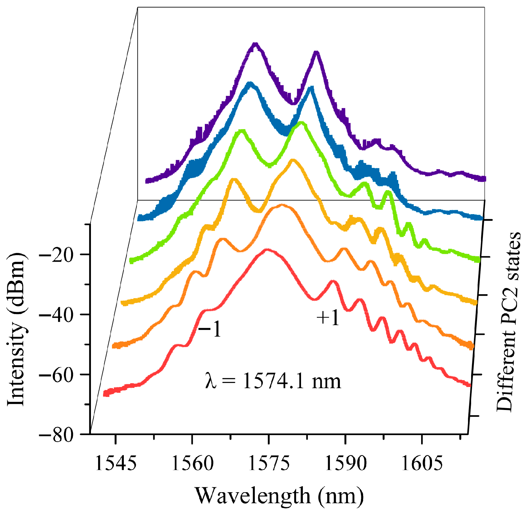
When the pump power is set to 190 mW, the red curve in Figure 11 represents the optical spectrum under the polarization-multiplexing asynchronous mode-locking state. However, the optical spectrum changes as PC2 is adjusted. In the optical spectral diagram, the mode-locking center and the secondary sidebands begin to exhibit varying degrees of blue shift. The sidebands on both sides of the optical spectrum gradually become smooth, and the intensity of the −1 sideband to the left of the mode-locking center increases continuously as the optical spectrum blue-shifts. Eventually, as the state of PC2 changes, the mode-locking center and the −1 sideband in the original red spectral curve dominate the gain competition, forming a double-peak spectrum. Meanwhile, the laser also transitions from the polarization-multiplexing asynchronous mode-locking state to the wavelength-multiplexing asynchronous mode-locking state. From the above experimental process, it can be concluded that the adjustment of PC2 in the laser is the key factor for switching between wavelength-multiplexing and polarization-multiplexing asynchronous pulses.

3.4.2. Numerical Analysis

To further analyze the mechanism underlying the switching between two multiplexing modes in the constructed laser, we perform a numerical simulation of the transmission curve of the Sagnac loop. Based on Equation (1), T = sin θ cos ϕ 2 2 = sin θ cos π B L λ 2 , presented in Section 2, which considers only the filtering effect of the Sagnac loop, it can be concluded that the maximum transmission is achieved when θ = π 2 + k π (k is an integer). At this condition, the FSR of the Sagnac loop transmission curve is jointly determined by the length of the PMF within the loop and its birefringence. As shown in Figure 12a,b, the FSR of the transmission curve decreases with increasing PMF length or birefringence.
Based on Equation (1), further considering the additional phase delay introduced by adjusting PC2, the transmission curve of the Sagnac loop is thereby refined as [30]
T = sin θ cos ϕ + ϕ P C 2 2
Here ϕ P C represents the additional phase delay introduced by PC2. As shown in Figure 13, the additional phase delay caused by PC2 shifts the transmission curve, thereby altering the position of the transmission peaks. This is the primary reason for the experimentally observed blue shift in the spectrum when adjusting PC2. In practical operation, adjusting PC2 changes the polarization state distribution within the laser cavity. This process not only introduces an extra phase delay that modifies the transmission of the Sagnac loop but also affects whether stable pulses can form along different polarization directions inside the cavity.

3.4.3. Adjustment of PC2 as the Key Factor for Switching

From the above experiments and numerical analysis, it can be seen that the red curve in Figure 11 corresponds to the spectrum in the polarization-multiplexing asynchronous mode-locked state, where the transmission peak of the Sagnac loop is located near the central mode-locking wavelength of λ = 1574.1 nm. Based on the birefringence of the PMF within the Sagnac loop, precise adjustment of the pump as well as PC1 and PC2 allows light to simultaneously oscillate along two orthogonal polarization directions in the cavity, ultimately forming polarization-multiplexing asynchronous pulse mode-locking. On this basis, adjusting PC2 alters the distribution of polarization states inside the laser cavity, causing the light to no longer satisfy the condition for simultaneous oscillation along the two orthogonal polarization directions. Concurrently, due to changes in phase and transmission, a dual-peak spectrum gradually forms, and the laser transitions from polarization-multiplexing asynchronous pulse mode-locking to wavelength-multiplexing asynchronous pulse mode-locking. The purple curve in Figure 11 represents the optical spectrum under the wavelength-multiplexing asynchronous mode-locking state. However, this asynchronous mode-locking state is unstable at this point. Through precise control of the pump power and PCs, a stable wavelength-multiplexing asynchronous mode-locking state, as shown in Figure 4, can ultimately be achieved. In summary, the adjustment of PC2 within the laser is a key factor for switching between wavelength- and polarization-multiplexing asynchronous pulse sequences, but obtaining stable asynchronous pulse mode-locking still requires a combination of precise control of the pump and PC1.

4. Comparison with Previous Related Work

As shown in Table 1, a total of two lasers similar to the present work have been identified, both capable of switching between wavelength- and polarization-multiplexing asynchronous pulse mode-locking. Considering the maximum output power of the LD, the maximum pump power is set to 380 mW under single-pulse mode-locking, resulting in an output power of 3.96 mW at this point. For the stability of asynchronous pulse mode-locking, the maximum pump power is set to 250 mW during wavelength-multiplexing mode-locking, yielding an output power of 2.42 mW. After separation by the CWDM, the powers of the two pulse sequences are 1.37 mW and 0.73 mW, respectively. In the polarization-multiplexing mode-locking state, the maximum pump power is set to 270 mW, corresponding to an output power of 2.67 mW. After separation by the PBS, the powers of the two pulse sequences are 1.2 mW and 1.08 mW, respectively. In this work, a Sagnac-loop-based filtering structure was employed, allowing continuous tunability of the mode-locking wavelength by adjusting PC2. Furthermore, since the laser output in this setup consists of NLPs, the laser exhibits higher pulse energy compared to previous similar works.

5. Conclusions

In this work, we demonstrate an erbium-doped mode-locked fiber laser based on a Sagnac loop. By precise control of the pump power and PCs, the laser can achieve tunable single-pulse mode-locking, as well as wavelength- and polarization-multiplexing asynchronous pulse mode-locking. The tunable single-pulse mode-locking and wavelength-multiplexing asynchronous pulse mode-locking primarily rely on the filtering effect of the intracavity Sagnac loop, while the polarization-multiplexing asynchronous pulse mode-locking mainly originates from the birefringence of the PMF inside the Sagnac loop. The two asynchronous pulse sequences are separated using a CWDM and a PBS, respectively, further confirming their multiplexing mechanisms. Experimental and numerical simulations are conducted to investigate the key factors governing the switching between wavelength- and polarization-multiplexing asynchronous pulses. To the best of our knowledge, this is the first demonstration of switching between wavelength- and polarization-multiplexing asynchronous pulse mode-locking in NLPs. Compared to previous related works, employing the Sagnac loop as a filter enables continuous tunability of the mode-locking wavelength, while the NLP output delivers higher pulse energy than that of conventional solitons. This work provides a potential light source with a simple architecture and strong switching capability for dual-comb systems.

Author Contributions

Writing—original draft preparation, Q.Y.; investigation, L.L., Y.C. and Y.Z.; supervision, X.Z. All authors have read and agreed to the published version of the manuscript.

Funding

This research was funded by China National Research Program (Grant 2022YFB3806900).

Institutional Review Board Statement

Not applicable.

Informed Consent Statement

Not applicable.

Data Availability Statement

The raw data supporting the conclusions of this article will be made available by the authors on request.

Conflicts of Interest

The authors declare no conflicts of interest.

References

  1. Minoshima, K.; Matsumoto, H. High-accuracy measurement of 240-m distance in an optical tunnel by use of a compact femtosecond laser. Appl. Opt. 2000, 39, 5512–5517. [Google Scholar] [CrossRef]
  2. Nakamura, T.; Ito, I.; Kobayashi, Y. Offset-free broadband Yb:fiber optical frequency comb for optical clocks. Opt. Express 2015, 23, 19376–19381. [Google Scholar] [CrossRef]
  3. Picque, N.; Haensch, T.W. Frequency comb spectroscopy. Nat. Photonics 2019, 13, 146–157. [Google Scholar] [CrossRef]
  4. Coddington, I.; Swann, W.C.; Newbury, N.R. Coherent Multiheterodyne Spectroscopy Using Stabilized Optical Frequency Combs. Phys. Rev. Lett. 2008, 100, 013902. [Google Scholar] [CrossRef] [PubMed]
  5. Yan, M.; Luo, P.L.; Iwakuni, K.; Millot, G.; Hänsch, T.W.; Picqué, N. Mid-infrared dual-comb spectroscopy with electro-optic modulators. Light Sci. Appl. 2017, 6, 761–768. [Google Scholar] [CrossRef]
  6. Millot, G.; Pitois, S.; Yan, M.; Hovhannisyan, T.; Bendahmane, A.; Hänsch, T.W.; Picqué, N. Frequency-agile dual-comb spectroscopy. Nat. Photonics 2016, 10, 27–31. [Google Scholar] [CrossRef]
  7. Yu, H.Y.; Zhou, Q.; Li, X.H.; Wang, X.H.; Kai, N. Phase-stable repetition rate multiplication of dual-comb spectroscopy based on a cascaded Mach-Zehnder interferometer. Opt. Lett. 2021, 46, 3243–3246. [Google Scholar] [CrossRef]
  8. Suh, M.G.; Yang, Q.-F.; Yang, K.Y.; Yi, X.; Vahala, K.J. Microresonator soliton dual-comb spectroscopy. Science 2016, 354, 600–603. [Google Scholar] [CrossRef]
  9. Luo, X.; Tuan, T.H.; Saini, T.S.; Nguyen, H.P.T.; Suzuki, T.; Ohishi, Y. Switchable dual-wavelength mode-locked fiber laser using Saganc loop mirror. Opt. Commun. 2020, 463, 125457. [Google Scholar] [CrossRef]
  10. Chen, J.; Zhao, X.; Yao, Z.; Li, T.; Li, Q.; Xie, S.; Liu, J.; Zheng, Z. Dual-comb spectroscopy of methane based on a free-running Erbium-doped fiber laser. Opt. Express 2019, 27, 11406–11412. [Google Scholar] [CrossRef] [PubMed]
  11. Chen, J.; Nitta, K.; Zhao, X.; Mizuno, T.; Minamikawa, T.; Hindle, F.; Zheng, Z.; Yasui, T. Adaptive-sampling near-Doppler-limited terahertz dual-comb spectroscopy with a free-running single-cavity fiber laser. Adv. Photonics 2020, 2, 036004. [Google Scholar] [CrossRef]
  12. Dai, M.L.; Liu, B.W.; Shirahata, T.; Sun, X.N.; Set, S.Y.; Yamashita, S. All-polarization-maintaining, efficiently wavelength-tunable, Er-doped mode-locked fiber laser with a compact reflective Lyot filter. Opt. Express 2023, 31, 27810–27820. [Google Scholar] [CrossRef] [PubMed]
  13. Dai, M.; Liu, B.; Ye, G.; Shirahata, T.; Ma, Y.; Yamaguchi, N.; Set, S.Y.; Yamashita, S. Pump-driven wavelength switching in an all-polarization-maintaining mode-locked fiber laser incorporating a CNT/PDMS saturable absorber. Opt. Laser Technol. 2024, 176, 111002. [Google Scholar] [CrossRef]
  14. Zhao, X.; Li, T.; Liu, Y.; Li, Q.; Zheng, Z. Polarization-multiplexed, dual-comb all-fiber mode-locked laser. Photon. Res. 2018, 6, 853–857. [Google Scholar] [CrossRef]
  15. Gu, X.; Wang, G.; Li, Y.; Gong, H.; Liang, Y.; Wu, T.; Wang, J.; Liu, Y. Polarization-multiplexed, single-cavity dual-comb fiber laser based on a birefringent crystal and a saturable absorber. Opt. Express 2023, 31, 56–64. [Google Scholar] [CrossRef]
  16. Cuevas, A.R.; Kbashi, H.J.; Stoliarov, D.; Sergeyev, S. Polarization dynamics, stability and tunability of a dual-comb polarization-multiplexing ring-cavity fiber laser. Results Phys. 2023, 46, 106260. [Google Scholar] [CrossRef]
  17. Zhang, C.H.; Wu, T.; He, S.; Zhang, C.Y.; Fu, B. Multiplexed dual combs in a bidirectional nanotube-mode-locked fiber laser. Opt. Laser Technol. 2024, 168, 109865. [Google Scholar] [CrossRef]
  18. Zhao, X.; Hu, G.; Zhao, B.; Li, C.; Pan, Y.; Liu, Y.; Yasui, T.; Zheng, Z. Picometer-resolution dual-comb spectroscopy with a free-running fiber laser. Opt. Express 2016, 24, 21833–21845. [Google Scholar] [CrossRef]
  19. Bajek, D.; Cataluna, M.A. Megahertz scan rates enabled by optical sampling by repetition-rate tuning. Sci. Rep. 2021, 11, 22995. [Google Scholar] [CrossRef]
  20. Wu, Z.C.; Liu, D.M.; Fu, S.N.A.; Li, L.; Tang, M.; Zhao, L.M. Scalar-vector soliton fiber laser mode-locked by nonlinear polarization rotation. Opt. Express 2016, 24, 18764–18771. [Google Scholar] [CrossRef]
  21. Wu, Z.C.; Fu, S.N.; Jiang, K.; Song, J.; Li, H.Z.; Tang, M.; Shum, P.; Liu, D.M. Switchable thulium-doped fiber laser from polarization rotation vector to scalar soliton. Sci. Rep. 2016, 6, 34844. [Google Scholar] [CrossRef]
  22. Li, T.; Zhao, X.; Chen, J.; Li, Q.; Xie, S.G.; Zheng, Z. Tri-Comb and Quad-Comb Generation Based on a Multi-Dimensional Multiplexed Mode-Locked Laser. J. Light Technol. 2019, 37, 5178–5184. [Google Scholar] [CrossRef]
  23. Jin, X.X.; Liu, R.Y.; Zhou, J.Y.; Li, Z.H.; Duan, Y.M.; Zhu, H.Y. Simultaneous generation of wavelength multiplexing and polarization multiplexing from a wavelength-tunable ultrafast fiber laser. Opt. Fiber Technol. 2024, 84, 103719. [Google Scholar] [CrossRef]
  24. Li, S.; Shao, J.; Shen, Q.; Shen, L.; Cao, Z.; Chen, J.; Wu, Z.; Sang, M. Multiwavelength Fiber Ring Laser with Selectable Grid Spacing. Acta Opt. Sin. 2007, 27, 1802–1806. [Google Scholar]
  25. Kim, R.K.; Han, Y.G. Switchable multiple lasing oscillations in an erbium-doped fiber ring laser using a single stage of a Sagnac loop mirror. Appl. Phys. B Lasers Opt. 2011, 103, 813–818. [Google Scholar] [CrossRef]
  26. Pandit, N.; Noske, D.U.; Kelly, S.M.J.; Taylor, J.R. Characteristic instability of fiber loop soliton lasers. Electron. Lett. 1992, 28, 455–457. [Google Scholar] [CrossRef]
  27. Man, W.S.; Tan, H.Y.; Demokan, M.S.; Wai, P.K.A.; Tang, D.Y. Mechanism of intrinsic wavelength tuning and sideband asymmetry in a passively mode-locked soliton fiber ring laser. J. Opt. Soc. Am. B 2000, 17, 28–33. [Google Scholar] [CrossRef]
  28. Chen, W.C.; Chen, G.J.; Han, D.A. Spectral sideband distribution asymmetry in fiber laser. Opt. Spectrosc. 2012, 113, 222–226. [Google Scholar] [CrossRef]
  29. Tang, D.Y.; Fleming, S.; Man, W.S.; Tam, H.Y.; Demokan, M.S. Subsideband generation and modulational instability lasing in a fiber soliton laser. J. Opt. Soc. Am. B 2001, 18, 1443–1450. [Google Scholar] [CrossRef]
  30. Wei, W.; Qin, G.L.; Li, B.; Duan, J.F. Linear cavity erbium-doped fiber laser employing PM-PCF based Sagnac loop comb filter for wavelength tunable laser generation. Laser Phys. 2021, 31, 105104. [Google Scholar] [CrossRef]
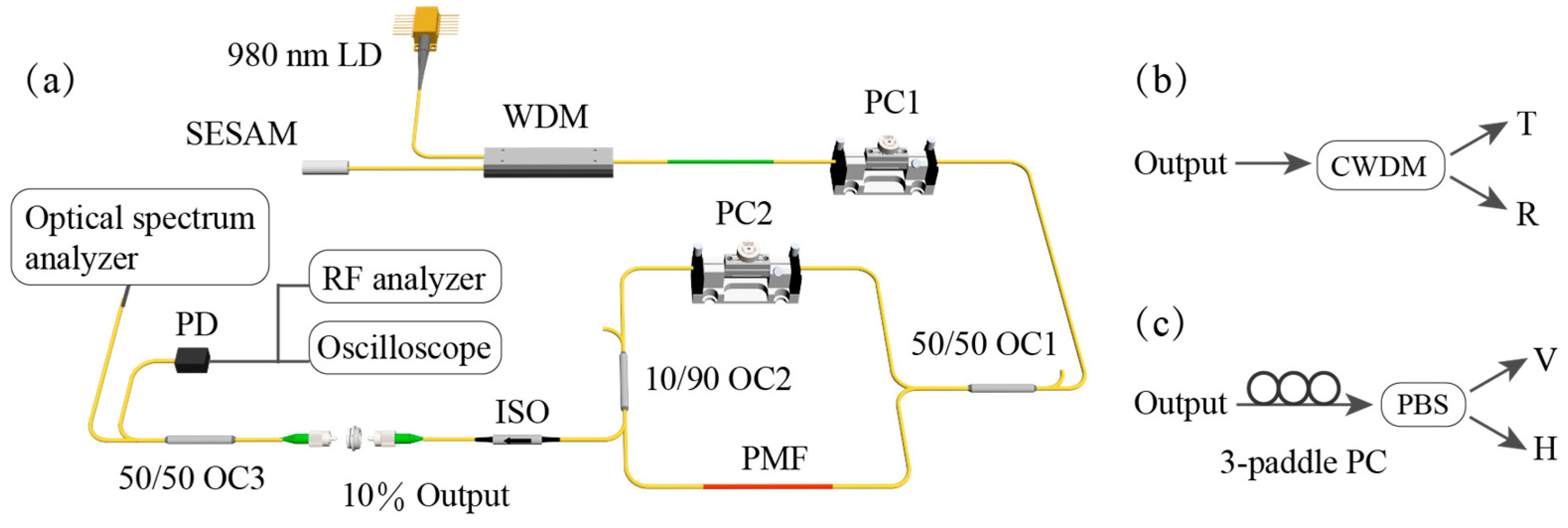
Figure 1. (a) Schematic diagram of the laser architecture. (b) Schematic diagram of asynchronous pulse sequence separation based on wavelength multiplexing and (c) polarization multiplexing.
Photonics 12 00961 g001
Figure 2. Output characteristics of the single-pulse sequence at three representative wavelengths: (a) optical spectra and (b) RF spectra. At the mode-locking center wavelength of λ2: (c) pulse train and (d) autocorrelation trace.
Photonics 12 00961 g002
Figure 3. (a) Spectrum, (b) output power, and repetition rate during 12 h of continuous operation in the single-pulse mode-locked state.
Photonics 12 00961 g003
Figure 4. Output characteristics of the wavelength-multiplexed asynchronous pulse sequences: (a) pulse interference pattern; (b,c) pulse trains at different moments; (d) RF spectrum; (e) optical spectrum; and (f) autocorrelation trace.
Photonics 12 00961 g004
Figure 5. (a) Spectrum, (b) output power, and (c) repetition rate and repetition rate difference during 12 h of continuous operation in the wavelength-multiplexing asynchronous mode-locked state.
Photonics 12 00961 g005
Figure 6. Pulse characteristics measured at the two output ports of the CWDM: (a) optical spectra, (b) RF spectra, and (c,d) pulse sequences.
Photonics 12 00961 g006
Figure 7. Output characteristics of the polarization-multiplexed asynchronous pulse sequences: (a) pulse interference pattern; (b,c) pulse trains at different moments; (d) RF spectrum; (e) optical spectrum; and (f) autocorrelation trace.
Photonics 12 00961 g007
Figure 8. (a) Spectrum, (b) output power, and (c) repetition rate and repetition rate difference during 12 h of continuous operation in the polarization-multiplexing asynchronous mode-locked state.
Photonics 12 00961 g008
Figure 9. Pulse characteristics measured at the two output ports of the PBS: (a) Optical spectra, (b) RF spectra, and (c,d) pulse sequences.
Photonics 12 00961 g009
Figure 10. Optical spectral variations with pump power during (a) wavelength-multiplexing and (b) polarization-multiplexing mode-locked states.
Photonics 12 00961 g010
Figure 11. Optical spectral variation with PC2 adjustment at a pump power of 190 mW.
Photonics 12 00961 g011
Figure 12. (a) Transmission spectra for different values of L at θ = π/2, B = 3.9 × 10⁻⁴, (b) Transmission spectra for different values of B at θ = π/2, L = 45 cm.
Photonics 12 00961 g012
Figure 13. Transmission spectra for different values of ϕ P C at θ = π/2, B = 3.9 × 10⁻⁴, L = 45 cm.
Photonics 12 00961 g013
Table 1. Comparison with previous related work.
Ref.Continuous Wavelength TunabilitySingle-Pulse Mode-Locking Output Pulse
Energy (pJ)
Wavelength Multiplexing
Output Pulse Energy (pJ)
Polarization Multiplexing
Output Pulse Energy (pJ)
Before Pulse SeparationAfter Pulse SeparationBefore Pulse SeparationAfter Pulse Separation
[22]No12.17---5.67&9.53
10.22---4.03&6.27
[23]Yes23.1825.75-48.58-
-32.19-64.81-
This workYes39.8788.6131.01&47.47108.8643.67&48.10
250.63153.1646.20&86.71168.9968.35&75.95
Disclaimer/Publisher’s Note: The statements, opinions and data contained in all publications are solely those of the individual author(s) and contributor(s) and not of MDPI and/or the editor(s). MDPI and/or the editor(s) disclaim responsibility for any injury to people or property resulting from any ideas, methods, instructions or products referred to in the content.