Article

DMSR: Dynamic Multipath Secure Routing Against Eavesdropping in Space-Ground Integrated Optical Networks

1
Department of Computer Science, Tsinghua University, Beijing 100084, China
2
The 54th Research Institute of China Electronics Technology Group Corporation, Shijiazhuang 050081, China
*
Author to whom correspondence should be addressed.
Photonics 2025, 12(10), 1039; https://doi.org/10.3390/photonics12101039
Submission received: 23 September 2025 / Revised: 15 October 2025 / Accepted: 20 October 2025 / Published: 21 October 2025

Abstract

With the continuous growth of global communication demands, the space-ground integrated optical network (SGION), composed of the satellite optical network (SON) and terrestrial optical network (TON), has gradually become a critical component of global communication systems due to its wide coverage, low latency, and large bandwidth. However, although the high directivity of laser communication can significantly enhance the security of data transmission, it still carries the risk of being eavesdropped on during the process of service routing. To resist eavesdropping attacks during service transmission in the SGION, this paper proposes a secure routing scheme named dynamic multipath secure routing (DMSR). In DMSR, a metric called the service eavesdropping ratio (SER) is defined to quantify the service leakage severity. The objective of DMSR is to reduce each service’s SER by switching its routing path proactively. To realize DMSR, heuristic algorithms are developed to sequentially search for optimal routing paths for service path switching in the TON and SGION. Finally, simulation results demonstrate that DMSR can achieve trade-offs between secure service transmission and network performance at different levels by adjusting its system parameters. Furthermore, the DMSR scheme significantly reduces the SER compared to the baseline schemes, while introducing acceptable increases in computation overhead and service latency.

1. Introduction

With the continuous growth of global information and communication demands, traditional terrestrial communication networks are gradually struggling to meet the communication requirements of long-distance, wide coverage, high data rate, and high reliability. Against this backdrop, low-earth orbit (LEO) satellite communication systems, leveraging their unique advantages, have become an important supplement to the new generation of global communication infrastructure. Compared with medium and high orbit satellites, LEO satellites boast advantages such as low communication latency, low launch costs, and flexible orbital deployment [1]. The satellite network, mainly based on LEO, is integrated with 3GPP standardization to address the coverage gap of ground 5G and subsequent 6G, ultimately building an integrated system of air, space, and earth to achieve ubiquitous connectivity across the entire domain [2]. They hold irreplaceable strategic value, especially in remote mountainous areas, oceanic regions, and emergency rescue scenarios. Internationally, SpaceX’s “Starlink” has deployed over 8000 satellites [3]. OneWeb has deployed more than 600 satellites in its first phase [4]. Amazon’s “Project Kuiper” will also accelerate its deployment in 2025 [5]. Also, European companies like Eutelsat are closely following suit. China’s satellite constellations are also catching up [6]. Allen Chang, an analyst at Goldman Sachs, predicts that 70,000 new satellites will be launched in the next five years, with 53,000 of them to be launched by China. This figure is 10 times the current number of satellites in orbit [7].
However, while LEO satellite networks are developing rapidly, they also face severe security challenges. Firstly, LEO satellite networks generally feature highly dynamic topological structures, fast node movement speeds, and short communication time slots, making traditional static network security models difficult to adapt to their operating environment. Secondly, the interconnection between LEO satellites is highly dependent on point-to-point laser links. While such links ensure high confidentiality, they also mean that once the network is attacked, its stability will be seriously threatened. In addition, satellite resources are limited, making it difficult to deploy security protocols with high computational requirements or energy consumption. Satellite networks are characterized by dynamics, irregularities, and the vulnerability of wireless communications. They lack centralized monitoring and protection mechanisms, thus being vulnerable to various attacks. The main security threats faced by satellite routing are as follows:
(1)
Blackhole Attack
A blackhole attack refers to a scenario where a malicious node in the network, during the route establishment phase, falsely claims to have the shortest path to the destination node, thereby luring surrounding nodes to forward data to it. However, instead of forwarding the data packets, it discards them, thus disrupting communication. This process is similar to a black hole, which only absorbs matter, hence the name “blackhole attack” [8].
(2)
DoS/DDoS
DoS refers to continuously sending a large number of requests to satellites or ground terminals in a short period of time, overwhelming the links and causing service interruptions. For example, Starlink has been subjected to DDoS attacks [9].
(3)
Communication Eavesdropping
Eavesdropping is an attack behavior that involves unauthorized access to information [10]. Attackers secretly intercept, monitor, or access communication data without being detected, aiming to steal sensitive information such as accounts, passwords, communication contents, and encryption keys. Since satellite communications rely on laser signals propagating in free space without physical medium protection, they are vulnerable to eavesdropping. Ground-based attackers can receive satellite signals using large-aperture antennas and demodulation systems. In broadcasting and data forwarding services, end-to-end encryption is often not implemented to save costs or reduce latency, which allows attackers to exploit vulnerabilities. Although there are no widespread reports of large-scale practical eavesdropping in actual combat, the following examples indicate that eavesdropping technology is already feasible.
For example, as mentioned in the literature, unauthorized and illegal access to patients’ private medical information occurs in hospitals [11]. The literature proposes two practical eavesdropping scenarios for optical communications in the satellite-to-HAPS (downlink) and HAPS-to-satellite (uplink) links, where an attacker’s spacecraft can eavesdrop on either the transmitted signals or the received signals [12]. Meng et al. assumed a satellite eavesdropper in the uplink satellite communication system, where the eavesdroppers are randomly distributed at any altitude according to the homogeneous binomial point process and attempt to intercept the signals transmitted from the ground terminals to the serving satellite [13]. Alexander Miller from the National University of Singapore pointed out in his paper that the payload transmission module of China’s quantum communication satellite “Micius” has a timing desynchronization issue. This problem allows eavesdroppers to distinguish between signal states and decoy states with a probability of 98.7% [14]. This study reveals that defects in actual equipment may undermine the security of quantum key distribution (QKD), which is theoretically secure. James Pavur, a researcher at the University of Oxford, demonstrated at the 2020 Black Hat Conference that using household TV equipment costing approximately $300, such as satellite dishes and DVB-S receivers, it is possible to intercept aeronautical internet data and reconstruct IP data packets [15]. In 2023, a cargo ship deviated from its route by 35 nautical miles in the Red Sea due to tampered navigation data. Attackers could alter the ship’s fuel supply instructions and cargo manifests by forging the frame check sequence (FCS) of satellite signals [16].
Due to the high latency of satellite networks, the impact of attacks is amplified, making them more difficult to detect and respond to in a timely manner [17]. Moreover, LEO satellites have limited resources, lacking sufficient capacity to deploy complex encryption or monitoring mechanisms [18]. Therefore, research on secure routing is extremely important. In this context, the issue of routing security has become a key link in the design of LEO optical networks [19]. In LEO satellite optical networks, the problem of secure routing is one of the core research directions for ensuring communication reliability and anti-attack capabilities. Secure routing refers to the selection of a trustworthy, reliable, non-eavesdropped, and non-tampered data transmission path in a dynamically networked environment with multiple satellites, so as to guarantee the security of the communication process and quality of service (QoS) [20].
At present, scholars both at home and abroad have conducted extensive research on secure routing in low-orbit satellite networks. He et al. [21] proposed a homogeneous quantum satellite network architecture (MRN) that supports key storage and relaying (SR). They defined the concept of storage relay topology (SRT) as a framework for dynamically describing the connection status and link weights of quantum satellite networks, which is used to guide the routing of global quantum key distribution (GQKD). Based on SRT, the SRT-RKA algorithm was developed, specifically for efficiently and dynamically allocating global keys for massive short message service (SMS) requests. Jiang et al. [22] conducted a review study on secure handoff, secure transmission control, key management, and secure routing. Matthias et al. [23] proposed a precoding algorithm to protect the downlink of multiple users from eavesdropping by multiple eavesdroppers. Zheng et al. [24] proposed an algorithm for users being eavesdropped on by multiple eavesdroppers simultaneously, which minimizes the total transmission power while maintaining secrecy constraints. Literature [25] takes communication security as a key goal, summarizes the involved security indicators in detail, focuses on eavesdropping security attacks, fully considers satellite beam patterns and path loss, conducts detailed modeling of satellite channels, and proposes a security design for satellite communication networks from the perspective of physical layer security. Literature [26] constructs a cognitive satellite-terrestrial network scenario where eavesdroppers illegally lurk, intending to eavesdrop during the primary and secondary user signal transmission between satellites and base stations.
Some advanced techniques, such as QKD, can detect eavesdropping attempts. However, current deployments do not yet provide continuous, wide-area coverage over dynamic space-ground paths. For the foreseeable future, many segments of space-ground integrated optical networks (SGIONs) will continue to rely on classical keys or operate in hybrid regimes. Against this background, we propose a secure routing technology whose principle is to avoid long-term use of the same route (which may lead to eavesdropping by potential attackers) by switching routes within a certain period of time.
The rest of this paper is organized as follows: Section 2 presents the system model. Section 3 illustrates the dynamic multipath secure routing (DMSR) scheme. Section 4 elaborates on the heuristic algorithms we developed. Section 5 presents the simulation results. Section 6 discusses the limitations of the proposed scheme. Finally, the paper is summarized in Section 7.

2. System Model

In this section, the system model of routing in the SGION is discussed, including the network architecture, network model, and service model.

2.1. Network Architecture

This study focuses on the integrated space-ground communication environment formed by the interconnection of satellite optical networks (SONs) and terrestrial optical networks (TONs), with a particular emphasis on addressing cross-layer secure routing challenges. As illustrated in Figure 1, the overall network topology comprises two primary components: the space layer and the ground layer. The ground network employs optical fibers for interconnection, whereas inter-satellite and satellite-to-ground links utilize laser communication technology. In the space layer, the network adopts a typical polar-orbit LEO constellation architecture, such as the Iridium constellation. Each satellite node is equipped with laser communication terminals, enabling multi-hop forwarding between satellites and forming a globally distributed high-speed spaceborne communication network [27]. Due to the continuous variation in orbital positions and time, satellite nodes exhibit high mobility, resulting in a highly dynamic network topology. The ground layer consists of multiple ground stations (GSs) and the core terrestrial IP network. Ground stations are geographically distributed and interconnected with the backbone networks. The terrestrial segment may integrate various heterogeneous networks, including mobile communication networks, the Internet of Things (IoT), and the Internet, providing user access and data aggregation functions [28]. For space-ground interconnection, the physical layer connectivity between LEO satellites and ground stations is established via laser communication links, enabling high-speed and low-latency data transmission [29].

2.2. Network Model

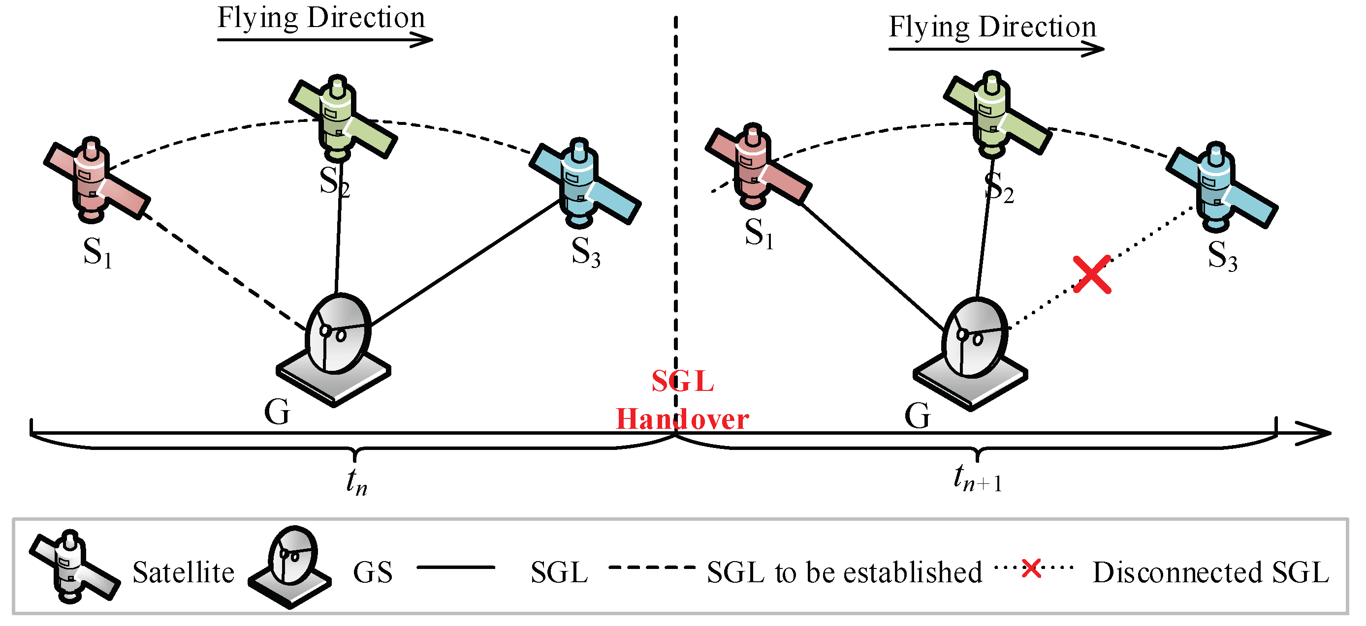
Considering the dynamics of the SGION, the network operation period is divided into multiple equal-length time slots, i.e., T = t 1 , t 2 , , t n , where t i denotes i -th time slot. The network topology is considered to be fixed within each time slot and only varies across different time slots. Note that the duration of each time slot is set to be extremely short (e.g., τ = 1 s), so it is reasonable to consider that SGL handovers occur exclusively at time slot boundaries rather than within any time slot, as shown in Figure 2. In each time slot, the network is modeled as a directed graph G V , E , where V = V S V G denotes the total set of nodes, and V S and V G denote the set of satellite nodes and ground nodes, respectively. E = E S E G E S G denotes the total set of links, and E S , E G , and E S G denote the set of ISLs, fiber links, and SGLs, respectively. Following the typical grid-mesh pattern, each LEO satellite establishes four ISLs with adjacent satellites, including two intra-orbit ISLs and two inter-orbit ISLs. Ground nodes with GSs connect to visible LEO satellites via laser links. The bandwidth capacities (the number of wavelengths) of ISLs, fiber links, and SGLs are denoted by W S , W G , and W S G .

2.3. Service Model

In this paper, service r is denoted by a quadruple s r , d r , A r , D r , where s r and d r denote the source and destination of service r . A r and D r denote the arrival instant (time slot) and duration (the number of time slots) of service r . When routing in the SGION, a service’s data typically undergo a cross-layer forwarding process. A typical end-to-end transmission path includes source ground node → source ground station → LEO satellites → multi-hop inter-satellite links → destination ground station → destination ground node, as depicted in Figure 1. Considering the eavesdropping threat inherent in this integrated space-ground network environment, this paper proposes a secure routing scheme tailored for heterogeneous multi-layer networks, which is illustrated in the next section.

3. The DMSR Scheme

In this section, the service eavesdropping ratio (SER) is first defined to quantify the severity of service data leakage. Then, the DMSR scheme is illustrated.

3.1. Service Eavesdropping Ratio

Quantifying the risk of eavesdropping is the first step to mitigating it in the SGION. Traditional binary models (secure/insecure) are too coarse to guide dynamic routing strategies. Therefore, we propose the SER metric, a continuous measure designed to quantify the severity of service data leakage from both temporal and probabilistic perspectives. The core idea is based on a risk exposure model: the longer the service data is transmitted over a specific link, the higher the probability that an eavesdropper lurking on that link can successfully intercept it. This probability depends on both the link’s inherent vulnerability (i.e., its eavesdropping probability p ( i , j ) ) and the relative exposure time of the service on that link. We first define the fundamental risk unit for service r on a single link ( i , j ) . If service r is transmitted over a single link, i.e., the routing path of r only contains one link, the SER of r on link ( i , j ) is defined as Equation (1), where p ( i , j ) denotes the eavesdropping probability of link ( i , j ) , D r ( i , j ) denotes the period when service r is transmitted over link ( i , j ) , and D r denotes the duration of service r . Note that the eavesdropping probability of a link is not a classic probability of a single event, but rather a risk coefficient per unit time. It encapsulates the time-independent vulnerability of the link, stemming from factors like its physical signal strength, geographical location, and the effectiveness of potential eavesdropping equipment in its vicinity. The term D r ( i , j ) / D r quantifies the fraction of the service’s total lifetime during which it is exposed on this specific link. This equation represents the proportion of service data deemed compromised due to transmission over this link.
S E R r ( i , j ) = p ( i , j ) × D r ( i , j ) D r
For an end-to-end path, we model it as a series system in risk analysis. In this model, a successful eavesdropping attack on any single link along the path compromises the entire service. Consequently, the total risk of the path is the sum of the risks of its constituent links. Thus, the SER of a service on a path is defined as Equation (2), where p a t h is the set of links constituting the routing path of r . This value represents the overall exposure risk of choosing this path for end-to-end transmission.
S E R r p a t h = ( i , j ) p a t h S E R r ( i , j ) = ( i , j ) p a t h p ( i , j ) × D r ( i , j ) D r
When a service is transmitted over multiple paths (i.e., dynamic path switching), an eavesdropper may choose to monitor any one of them. Under a worst-case security assumption, we posit that the eavesdropper can always target the most vulnerable path (the one with the highest SER). Therefore, the overall SER for the service is determined by the maximum SER among all paths used, as given in Equation (3), where P a t h s denotes the set of paths over which the service r is transmitted.
S E R r = max p a t h P a t h s S E R r p a t h

3.2. DMSR

The objective of the DMSR scheme is to reduce the service’s SER by switching the routing path frequently. The objective function is formulated as Equation (4), where R denotes the set of services, S E R r denotes the SER of service r .
Minimize S E R r
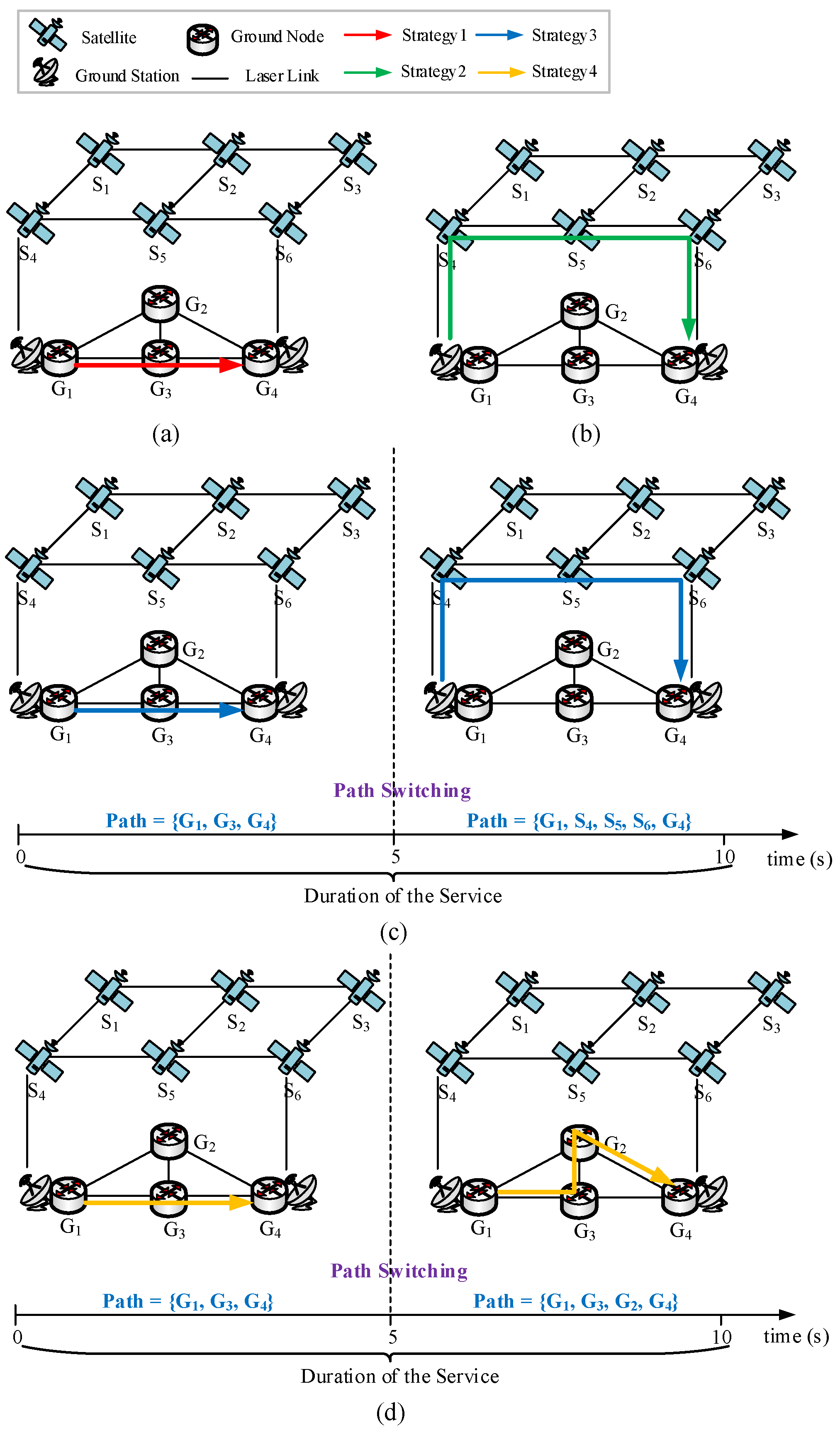
To further illustrate the DMSR scheme, four routing strategies for a service r are shown in Figure 3a–d. Service r ’s source and destination are G1 and G4, and its arrival time and departure time are 0s and 10s, respectively. Strategy 1 exclusively utilizes ground nodes for relaying and maintains a fixed path {G1, G3, G4}. Strategy 2 solely employs satellite nodes for relaying and maintains a fixed path {G1, S4, S5, S6, G4}. At t = 5 s, Strategy 3 performs complete path switching from {G1, G3, G4} to {G1, S4, S5, S6, G4}, while Strategy 4 executes partial path switching from {G1, G3, G4} to {G1, G3, G2, G4}. For ease of illustration, we assume an eavesdropping probability of 0.1 for each link. According to Equations (1)–(3), service r ’s SER in Strategy 1 is 0.1 × 1 + 0.1 × 1 = 0.2, the service r ’s SER in Strategy 2 is 0.1 × 1 + 0.1 × 1 + 0.1 × 1 + 0.1 × 1 = 0.4, the service r ’s SER in Strategy 3 is Max{0.1 × 0.5 + 0.1 × 0.5, 0.1 × 0.5 + 0.1 × 0.5 + 0.1 × 0.5 + 0.1 × 0.5} = 0.2, and the service r ’s SER in Strategy 4 is Max{0.1 × 0.5 + 0.1 × 0.5, 0.1 × 0.5 + 0.1 × 0.5 + 0.1 × 0.5} = 0.15. Based on the above calculation, we find that different routing strategy has totally different SER. Further, comparison between Strategy 1 and Strategy 2 reveals that longer paths (higher hop counts) yield greater SER. Consequently, path selection should prioritize shorter routes. Comparing Strategy 1 and Strategy 4 confirms that routing path switching can effectively reduce SER. However, this benefit is not universal. Though implementing path switching, Strategy 3 maintains identical SER to Strategy 1. This equivalence occurs because Strategy 3’s longer path negates the transmission-time reduction gained from path switching. Although path switching can reduce SER, it introduces computational/signaling overhead and delay jitter. Consequently, unlimited switching frequency proves unsustainable. In practical applications, we must constrain the number of paths switching to balance anti-eavesdropping gains against network operational costs.

4. Heuristic Algorithms

In this section, heuristic algorithms are developed to realize the DMSR scheme, as given in Algorithms 1–3. Specifically, Algorithm 1 is the overall algorithm based on Algorithms 2 and 3, and Algorithms 2 and 3 are used to determine the routing path in the TON and SGION, respectively.
Algorithm 1: Dynamic Multipath Secure Routing (DMSR)
Input: TON topology G ( V G , E G ) , SGION topology S G ( V , E ) , service request r , the number of service path switches n , the number of the shortest paths k ;
Output: the set of routing paths P a t h s , the set of path switching instants S T ;
1: Initialize: P a t h s , S T , t A r ;
2: Calculate the path switching time interval Δ t = D r / n + 1 ;
3: Call Algorithm 2 to obtain the routing path p t G O N at time slot t in the TON;
4: if p t G O N  then
5:  Add p t G O N and t to P a t h s and S T , respectively;
6:   t t + Δ t ;
7: else
8:  Call Algorithm 3 to obtain the routing path p t S G I O N and next path switching instant t n s in the SGION;
9:  if  p t S G I O N  then
10:   Add p t S G I O N and t to P a t h s and S T , respectively;
11:    t t n s ;
12:  else
13:   Block service r ;
14:  end if
15: end if
16: while  t < A r + D r  do
17:  Call Algorithm 2 to obtain the routing path p t G O N on the TON;
18:  if p t G O N  then
19:   Add p t G O N and t to P a t h s and S T , respectively;
20:    t t + Δ t ;
21:  else
22:   Call Algorithm 3 to obtain the routing path p t S G I O N and next path switching instant t n s in the SGION;
23:   if p t S G I O N  then
24:    Add p t S G I O N and t to P a t h s and S T , respectively;
25:     t t n s ;
26:   else
27:    Block service r ;
28:   end if
29:  end if
30: end while
31: return P a t h s , S T ;
Algorithm 2: Routing Path Determination in the TON
Input: time slot t s , TON topology G ( V G , E G ) at time slot t s , service request r , path switching time interval Δ t , the number of the shortest paths k ;
Output: routing path p at time slot t s ;
1: Initialize: p ;
2: for t = t s to t s + Δ t  do
3:  for each link ( i , j ) E G  do
4:   if  w ( i , j ) r e m t = 0  then
5:    Remove link ( i , j ) from G ;
6:   end if
7:  end for
8: end for
9: Use the KSP algorithm to search the k shortest paths P a t h s between s r and d r in graph G ;
10: for each path p P a t h s  do
11:  Calculate the SER of service r , assuming its remaining data is fully transmitted through path p ;
12: end for
13: Obtain the path with the minimum SER in P a t h s as p ;
14: return p ;
Algorithm 3: Routing Path Determination in the SGION
Input: time slot t s , SGION topology S G ( V , E ) at time slot t s , service request r , path switching time interval Δ t , the number of the shortest paths k ;
Output: routing path p at time slot t s , next path switching instant t n s ;
1: Initialize: p , t n s t s + Δ t , S G p r e S G ;
2: for t = t s to t n s  do
3:  for each link ( i , j ) E  do
4:   if  w ( i , j ) r e m t = 0 or x ( i , j ) ( t ) = 0  then
5:    Remove link ( i , j ) from S G ;
6:   end if
7:  end for
8:  if there is no path between s r and d r in graph S G  then
9:    S G S G p r e ;
10:    t n s t ;
11:   break;
12:  else
13:    S G p r e S G ;
14:  end if
15: end for
16: Use the KSP algorithm to search the k shortest paths P a t h s between s r and d r in graph S G ;
17: for each path p P a t h s  do
18:  Calculate the SER of service r , assuming its remaining data is fully transmitted through path p ;
19: end for
20: Obtain the path with the minimum SER in P a t h s as p ;
21: return p , t n s ;
Algorithm 1 is the main routine that coordinates path switching for a service request. When a service request arrives at the network, Algorithm 1 first searches for available paths in the TON. If no available path is found, it subsequently searches for available paths in the SGION. If no path is still found, the service will be blocked. The inputs of Algorithm 1 include two system parameters, which are the number of service path switches n and the number of the shortest paths k . In our proposed DMSR scheme, the path of a service may undergo multiple switches to resist eavesdropping. Therefore, the outputs of Algorithm 1 are the set of routing paths for a service and the corresponding path switching instants. In Step 1, t is initialized as an indicator to indicate when to carry out path switching. In Step 2, the service path switching time interval is calculated according to the service duration and the pre-set service path switching count. This is the default time interval between consecutive path switches. In Steps 3–15, the initial routing path r is determined by calling Algorithm 2 and Algorithm 3 in order. Similarly, the routing paths of r at subsequent time slots are obtained in Steps 16–30. Note that when calling Algorithm 3 for routing in the SGION, the resulting service path may contain intermittent SGLs. Consequently, the subsequent path switching instant for the service may vary and no longer adhere to the default interval. The while loop ensures that path switching occurs periodically or adaptively based on network conditions.
As illustrated above, Algorithm 2 is used to obtain the routing path in the TON. In Steps 2–8, the link wavelength resource availability is checked. For each time slot from t s to t s + Δ t , and for each link ( i , j ) in the TON, the remaining wavelength resource w ( i , j ) r e m ( t ) is calculated. This calculation is based solely on services already established at time slot t (future services are unpredictable). Specifically, w ( i , j ) r e m ( t ) is the total number of wavelengths on link ( i , j ) minus the number allocated to active services at time slot t . Note that in this paper, we assume that each node (including satellite node and ground node) is capable of wavelength conversion. Therefore, we only consider the wavelength capacity constraint of the links and not the wavelength continuity constraint. If w ( i , j ) r e m ( t ) = 0 for any time slot in the interval, the link is removed from the graph G . This ensures that only links with continuous resource availability are considered. In Step 9, the k shortest paths (KSP) algorithm is applied to the updated graph G to find k candidate paths between the source and the destination. In Steps 10–12, for each candidate path, the SER is computed according to Equation (3), assuming the service’s remaining data are fully transmitted through that path. Finally, the path with the minimum SER is obtained as the final routing path in the TON.
Algorithm 3 is proposed to determine the routing path in the SGION, accounting for dynamic topology and resource changes. Considering that the network topology and available wavelength resources vary over time, our proposed heuristic algorithms support dynamic adaptation of the actual path switching count based on real-time network conditions and link availability to reduce the service blocking rate. Consequently, the actual path switching instant may deviate from its pre-set value. Correspondingly, the outputs of Algorithm 2 include not only the routing path at time slot t s but also the next path switching instant t n s . In Step 1, S G p r e is initialized to store the network topology at the previous time slot as a fallback. In Steps 3–7, the link wavelength resource availability and link connectivity are checked. The link remaining wavelength resource calculation is similar to Algorithm 2. The link connectivity is obtained based on predictable satellite trajectories, and we use a binary variable x ( i , j ) ( t ) to denote whether link ( i , j ) is connected at time slot t . For each time slot from t s to t n s , and for each link ( i , j ) , if either w ( i , j ) r e m t = 0 or x ( i , j ) ( t ) = 0 , the link is removed from graph S G . After updating S G , if no path exists between s r and d r at time slot t , the algorithm reverts to the last viable topology S G p r e and sets t n s = t . This forces an immediate path switching to avoid service disruption. Otherwise, S G p r e is updated to the current S G . In Step 16, the KSP algorithm is employed to find k candidate routing paths in the final S G . In Steps 17–19, the SER of r on each path is calculated as Algorithm 2. Finally, the path with the minimum SER is selected as the final routing path in the SGION.
The time complexity of Algorithm 2 is O D r E G + k V G E G + V G log V G , where V G and E G denote the number of nodes and links in the TON, respectively. The time complexity of Algorithm 3 is O D r V 2 + k V E + V log V , where V and E denote the number of nodes and links in the SGION, respectively. Based on the time complexities of Algorithms 2 and 3, the time complexity of Algorithm 1 is O n D r V 2 + k V E + V log V .

5. Performance Evaluation

In this section, the performance of the DMSR scheme that is realized by our proposed heuristic algorithms is evaluated by extensive simulations.

5.1. Simulation Setup

In this paper, the Iridium constellation and the terrestrial network NSFNET are used to construct the SON and TON, respectively. Specifically, Iridium is a Walker Star constellation with 6 orbit planes and 11 satellites per orbit plane, and its orbit altitude and inclination are 780 km and 86.4°, respectively. NSFNET is a ground network connecting U.S. supercomputers and universities with 14 nodes and 21 links. Also, each ground node is configured with a GS to establish SGLs with visible satellites. The Poisson process is employed to simulate the dynamic arrival process of service requests with an arrival rate λ = 1 new arrival per second. The duration of services follows the exponential distribution with the service rate μ = 1/100 to 1/700 to simulate different network load conditions. The source and destination of each service request are randomly selected from ground nodes. All simulation parameters are summarized in Table 1. To avoid randomness in results, each simulation is run 5 times, and the average outcomes are obtained.

5.2. Influence of System Parameters

As illustrated in Algorithm 1, the performance of our proposed DMSR algorithm is influenced by two system parameters, which are the number of service path switches n and the number of shortest paths k . To further evaluate the impact of n and k on algorithm performance, extensive simulations are conducted to obtain the service blocking rate, average service path switching count, average SER, and average band utilization of the DMSR algorithm with different system parameters under light ( μ = 1/100), medium ( μ = 1/300), and heavy ( μ = 1/700) network loads. In addition, to compare the routing computation time overhead and QoS metrics under different system parameter configurations for the DMSR scheme, we simulated the average routing computation time, average service latency, and average latency jitter under a light network load. In this scenario, the service blocking rate was zero for all parameter sets, allowing for a fair comparison.
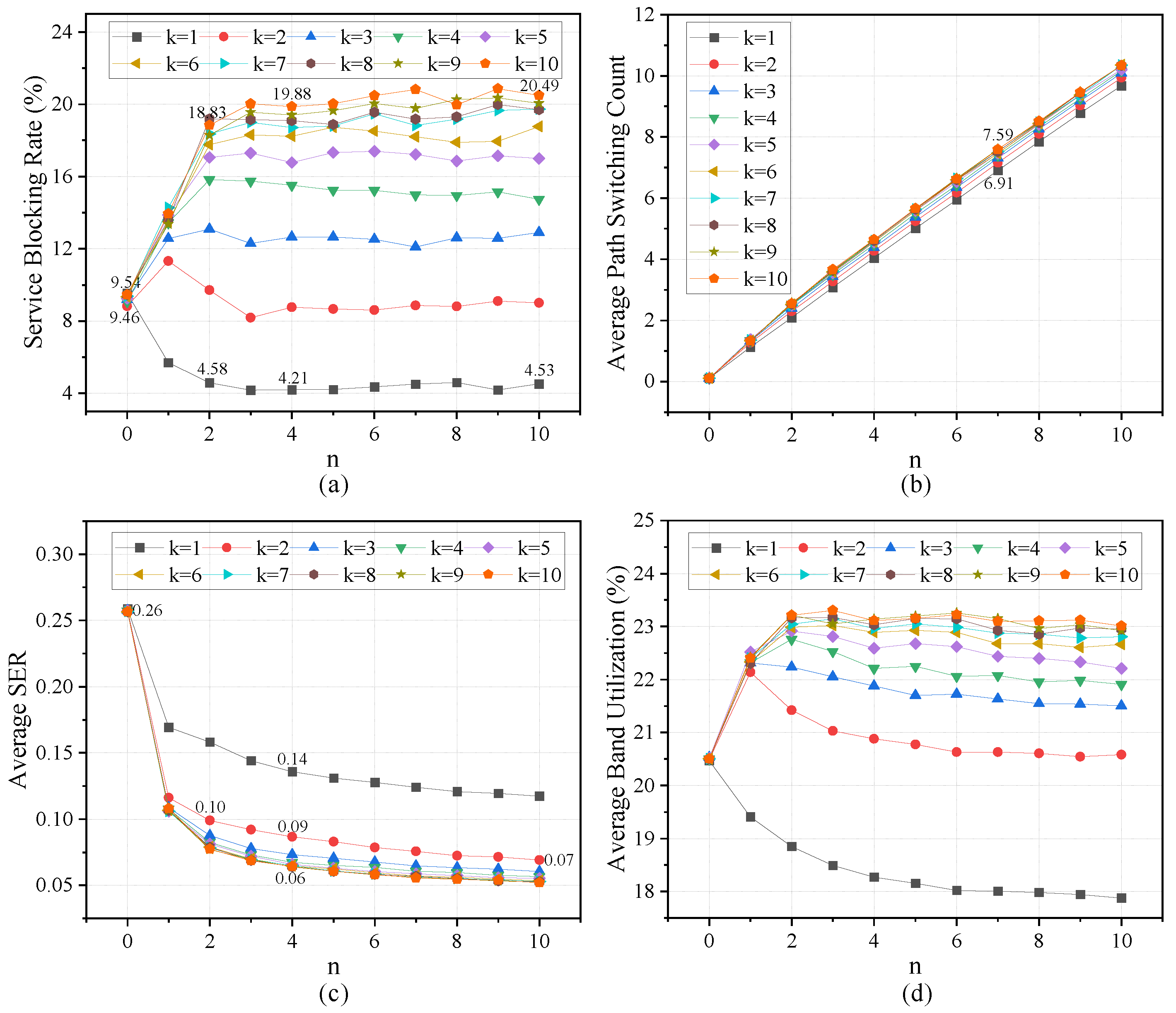
Figure 4 shows the performance of the DMSR algorithm with different system parameters under light network load ( μ = 1/100). Since the network load is very light, the service blocking rates of the DMSR algorithm with different system parameters are identical and equal to 0, as shown in Figure 4a. As shown in Figure 4b, with the increase in n , the average service path switching count also rises, which demonstrates that parameter n can indeed control the service path switching frequency. In addition, the algorithm with different k exhibits identical path switching counts, indicating that the system parameter k does not affect service path switching frequency under light network load. In Figure 4c, when n = 0 , the algorithm with different k exhibits identical average SER. When n > 1 , average SER decreases as k increases. For example, when n = 2 , the average SER decreases from 0.22 to 0.08 as k increases from 1 to 10. Moreover, when n > 1 , further increasing n does not yield further reduction in SER. This occurs because the multiple shortest paths have many overlapped links. Consequently, additional path switching cannot further decrease the SER. In Figure 4d, when k > 1 , as n increases, the band utilization first increases and then stabilizes. This indicates that once n exceeds a certain value, its impact on band utilization becomes negligible. Additionally, when n > 1 , band utilization increases with increasing k . This occurs because larger k provides more alternative paths for service switching. The DMSR algorithm will select longer routing paths for service path switching, which will consume more band resources and thereby increase band utilization. Note that under the light network load, the service blocking rate has already reached its minimum, so the increase in band utilization reflects greater consumption of band (wavelength) resources.
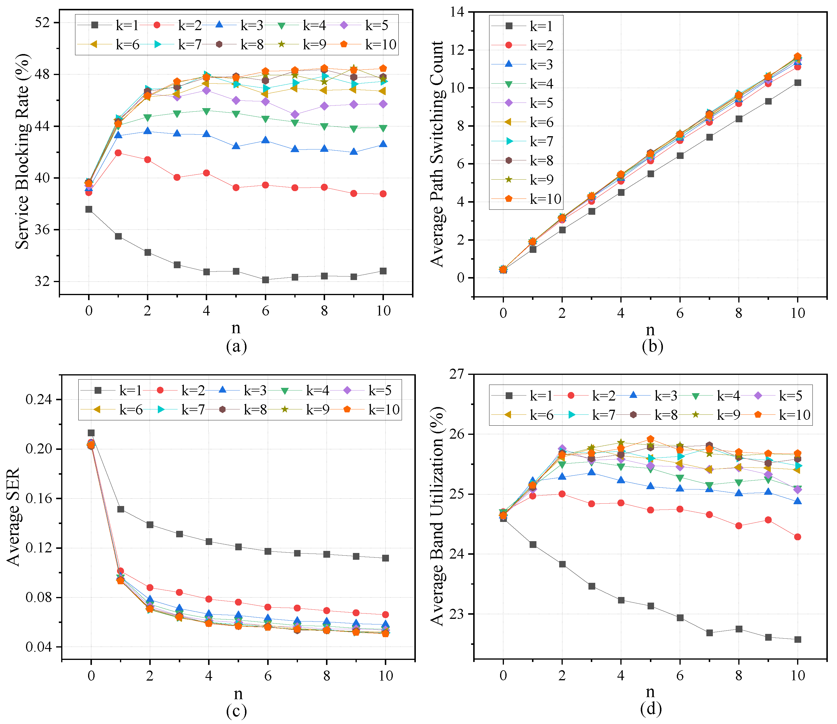
Figure 5 shows the performance of the DMSR algorithm under medium network load ( μ = 1/300). In Figure 5a, when n < 2 , the service blocking rate changes significantly with increasing n , whereas when n 2 , further increases in n have little impact on the blocking rate. For example, at k = 1 , as n increases from 0 to 2, the blocking rate decreases by 4.88%, but only decreases by 0.05% when n increases from 2 to 10. Notably, when k is set to 3 to 10, as n increases from 0 to 2, the blocking rate significantly increases. This occurs because the DMSR algorithm with larger k will select longer paths for services, which will consume more band resources, thereby increasing the service blocking rate. On the other hand, when n is fixed, the service blocking rate gradually increases with increasing k . For instance, at n = 4 , as k increases from 1 to 10, the service blocking rate increases by 15.67%. The increase in service blocking rate is mainly due to larger k leading to longer paths and greater band resource consumption. Figure 5b shows that when n is fixed, as k increases, the service path switching count gradually increases. For example, at n = 6 , as k increases from 1 to 10, the service path switching count increases by 9.84%. The increase in service path switching frequency is attributed to larger k providing more path selection options. In Figure 5c, as n increases, the average SER decreases, especially when n increases from 0 to 2. For example, at k = 2 , the service decreases by 0.16 as n increases from 0 to 2, and by 0.03 when n further increases from 2 to 10. For system parameter k , when n 2 , as k increases, the SER significantly decreases, especially when k increases from 1 to 2. For example, at n = 4 , as k increases from 1 to 2, the SER decreases by 0.05; as k further increases from 2 to 10, the SER only decreases by 0.03. Figure 5d shows that when n 2 , as k increases, the band utilization decreases, and the band utilization of k = 1 is significantly lower than other system parameter configurations. Note that the band utilization is consistent with the service blocking rate, demonstrating that the DMSR algorithm with larger k will consume more band resources. To further evaluate the system parameters n and k , simulations are conducted under heavy network load ( μ = 1/700), and corresponding results are shown in Figure 6. Comparing Figure 5 and Figure 6, we can find that the simulation results under heavy network load are similar to those under medium network load.
Figure 7a,b present a comparison of the average routing computation time and QoS metrics for the DMSR scheme across different system parameter configurations under light network load ( μ = 1/100). In Figure 7a, as n increases, the average routing computation time also rises, and this growth becomes more pronounced with larger values of k . For example, when k = 1, increasing n from 0 to 10 leads to a 17.87% increase in the average routing computation time. In contrast, when k = 10, increasing n from 0 to 10 results in a much larger increase of 58.42%. This occurs because a larger n leads to a higher average path switching frequency for services, necessitating more frequent routing computations, which in turn increases the computational time overhead. Furthermore, a larger k amplifies this effect, as the increased number of route calculations requires significantly more time. As shown in Figure 7b, the trends of the average service latency and average service latency jitter are almost identical as n and k increase. When k = 1, both the average service latency and the latency jitter remain nearly constant with the increase in n , staying at 7 ms and 0 ms, respectively. For other values of k , both the average latency and the latency jitter first increase sharply and then increase gradually or remain unchanged as n grows. As n increases, the average path switching frequency for services also rises, which leads to the selection of longer routing paths in the next path switching instant to maintain a lower SER and finally increase the average latency. The increase in the average latency jitter is a natural consequence of the increased number of path switches. In contrast, when n remains constant, both the average service latency and latency jitter gradually increase with the increase in k . The reason is that as k increases, longer and more diverse paths will be selected when the path needs to be switched.
According to results in Figure 4, Figure 5, Figure 6 and Figure 7, we can conclude that system parameters n and k will greatly impact the performance of the DMSR algorithm in terms of service blocking rate, path switching count, SER, band utilization, routing computation time, service latency, and service latency jitter. Generally, increasing n and k can reduce the SER, but at the cost of increasing the service blocking rate, the routing computation overhead, and the QoS metrics. Consequently, we need to set appropriate n and k to achieve a good trade-off among these key metrics. Further observation of Figure 5, Figure 6 and Figure 7 reveals that increasing n beyond 2 and k beyond 4 yields only marginal reductions in the SER. Additionally, the service blocking rate, average routing computation time, average service latency, and average latency jitter at k = 4 remain relatively low. Consequently, we set n = 2 and k = 4 in subsequent simulations to obtain a balanced optimization among service blocking rate, SER, routing computation overhead, and QoS metrics.

5.3. Performance Comparison

To further evaluate the performance of our proposed DMSR scheme, the DMSR scheme is compared with three secure routing schemes of the shortest path routing (SPR) scheme, the eavesdropping-aware routing and wavelength allocation (EA-RWA) scheme [30], and the random routing (RAND) scheme [31], which are detailed as follows:
In the SPR scheme, service paths are determined by Dijkstra’s algorithm and will not switch until SGL handovers along the current path occur.
In the EA-RWA scheme, the KSP algorithm is first used to obtain k shortest paths. Then, the SER of each path is calculated, and these k paths are sorted in ascending order according to their SER values. Finally, the path with the minimum SER and sufficient resources is selected as the final routing path and will not switch until SGL handovers along the current path occur.
In the RAND scheme, each time a path switch occurs (including the initial routing path determination), one of the following methods—shortest path, Algorithm 2, or Algorithm 3—is randomly selected to determine the routing path. The routing path will not switch until SGL handovers along the current path occur.
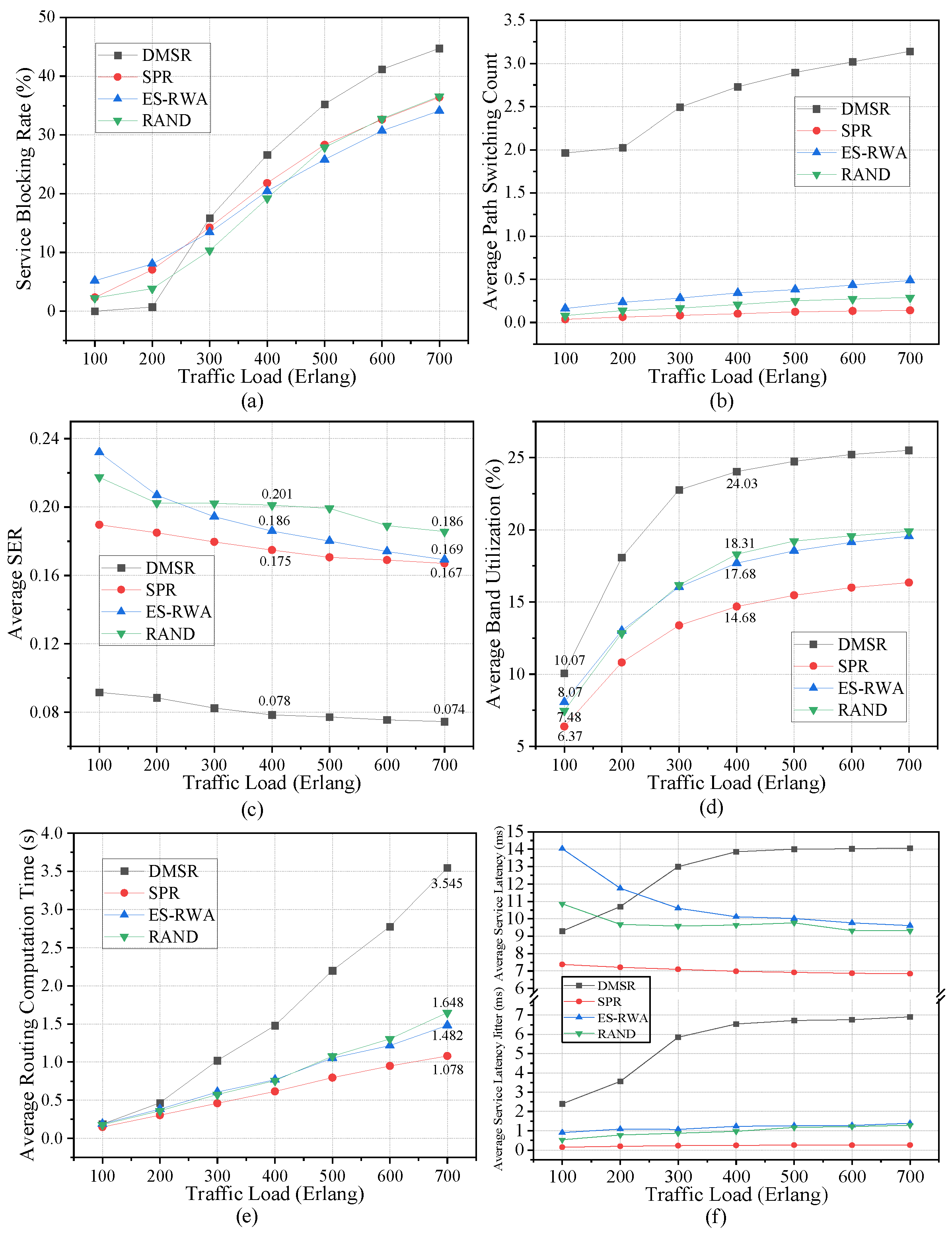
First, the eavesdropping probability of each link is set to 0.1, and the simulation results are shown in Figure 8. Figure 8a shows that as traffic load increases, the service blocking rates of all four schemes gradually increase. Moreover, when the traffic load is <300, the service blocking rate of the DMSR scheme is lower than that of other schemes. Whereas when the traffic load is ≥300, the service blocking rate of DMSR becomes the highest. The reason for the increase in service blocking rate is that DMSR selects longer paths during service path switching to reduce SER, which consumes more band resources, thereby reducing the number of services that can be transmitted through the network. Figure 8b shows that as traffic load increases, the path switching count of DMSR gradually increases, whereas the path switching count of other schemes remains nearly constant. For DMSR, although we set the number of path switches n to 2, the actual path switching count gradually increases with the increase in the traffic load. The actual path switching count gradually increases with the increase in the traffic load. This occurs because diminishing network bandwidth resources prompt the DMSR scheme to select paths with shorter remaining link durations for service path switches, thereby increasing the actual service path switching count. Furthermore, note that the service path switching count of the SPR scheme is not 0. The reason is that though the DMSR scheme does not proactively switch routing paths for services, it considers the path switching caused by SGL handovers with satellite-to-ground relative motions. Figure 8c shows that the SER of DMSR is significantly lower than that of other schemes. For example, at the traffic load = 400 Erlang, compared to SPR, ES-RWA, and RAND, the SER of DMSR is reduced by 55.43%, 58.06%, and 56.21%, respectively. At the traffic load = 700 Erlang, compared to SPR, ES-RWA, and RAND, the SER of DMSR is reduced by 55.69%, 61.19%, and 60.22%, respectively. The decrease in the SER demonstrates that DMSR can indeed reduce the SER compared to other schemes. Figure 8d shows that the band utilization of DMSR is significantly higher than that of other schemes, especially when the traffic load is heavy. For instance, at the traffic load = 100 Erlang, compared to SPR, ES-RWA, and RAND, the band utilization of DMSR is improved by 3.7%, 2%, and 2.59%, respectively. At the traffic load = 400 Erlang, compared to SPR, ES-RWA, and RAND, the band utilization of DMSR is improved by 9.35%, 6.35%, and 5.72%, respectively. Note that when the traffic load ≥ 300 Erlang, the service blocking rate of DMSR is higher than that of other schemes, which demonstrates that DMSR will consume more band resources. Figure 8e shows that the routing computation overhead of DMSR is higher than that of other schemes, especially when the traffic load is heavy. For example, when the traffic load is 700 Erlang, compared to SPR, ES-RWA, and RAND, the average routing time of DMSR is increased by 228.85%, 139.2%, and 115.11%, respectively. This is because DMSR proactively switches service paths to reduce the SER. This proactive path switching increases the number of routing computations, thus leading to greater time overhead. By comparison, SPR involves the fewest service path switches and thus the fewest path computations, leading to the smallest time overhead. Figure 8f shows that when the traffic load ≥300 Erlang, the average service latency of DMSR is higher than that of other schemes. This is because, in DMSR, as the number of path switches for a given service increases, longer paths are selected during each switch to achieve a lower SER, thus leading to an increase in service latency. Figure 8f also shows that DMSR consistently exhibits the highest latency jitter. This higher jitter is caused by the increased number of service path switches inherent to DMSR.
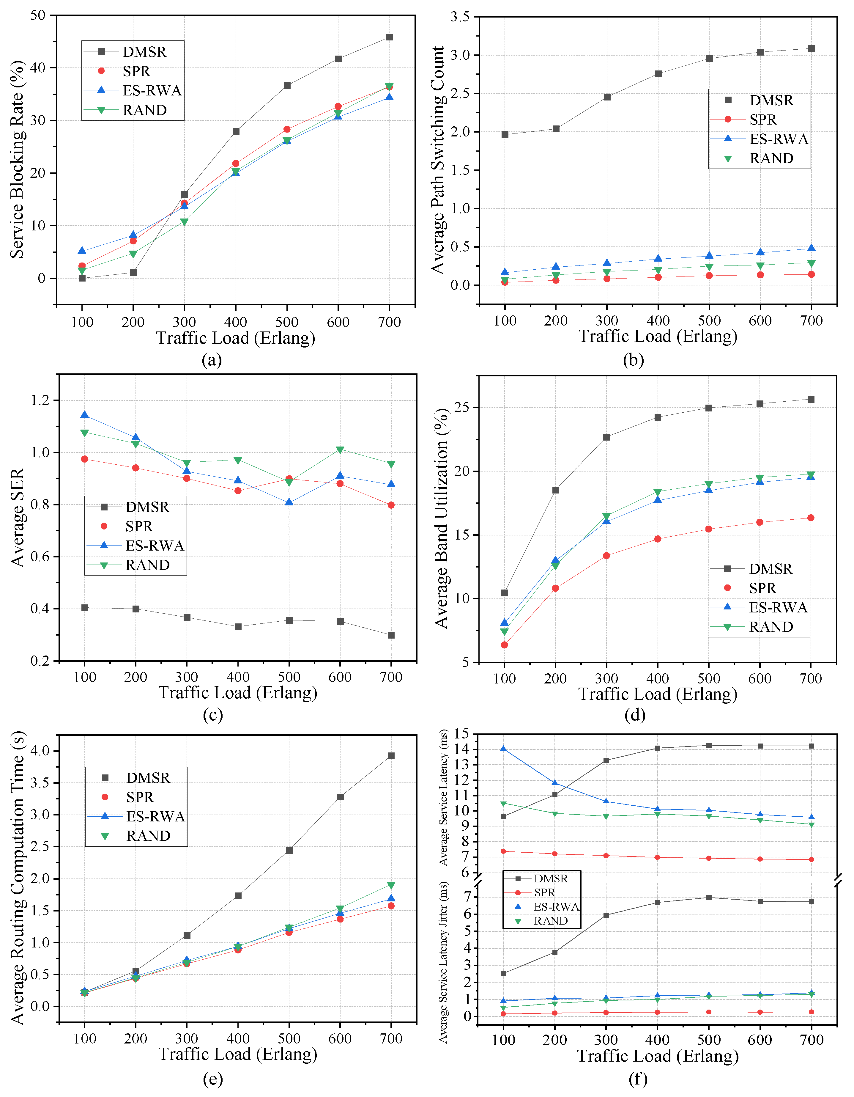
To further evaluate the performance of DMSR, we rerun simulations with the eavesdropping probability of each link being set to random values uniformly distributed over [0, 1], and present the results in Figure 9. We can find that the results in Figure 9 are very similar to the results in Figure 8. Specifically, compared to the other three schemes, the DMSR scheme has a higher service blocking rate, path switching count, band utilization, routing computation time, service latency, service latency jitter, and significantly lower SER.
Based on the results in Figure 8 and Figure 9, we can conclude that DMSR effectively reduces SER, albeit at the cost of increased service blocking rate, routing computation overhead, service latency, and latency jitter. We argue that a certain degree of degradation in network performance is a necessary and justified sacrifice to ensure secure (anti-eavesdropping) service transmission. In addition, in our proposed DMSR scheme, system parameters n and k can be adjusted according to practical requirements to strike a balance between service security and network performance, demonstrating the flexibility of the DMSR scheme.

6. Discussion

The DMSR scheme proposed in this paper attempts to resist eavesdropping through proactive service path switching. However, the scheme still has some limitations. First, the DMSR scheme only considers eavesdropping on links while overlooking potential eavesdropping on nodes. In fact, eavesdroppers can obtain service data by intercepting communications at either satellite or ground nodes. Second, physical attributes such as link signal-to-noise ratio (SNR) are not taken into account, even though link capacity and the service leakage severity are closely related to these characteristics. Therefore, we will further consider eavesdropping on nodes and eavesdropping-related physical characteristics to establish a more accurate eavesdropping model in our subsequent research. Moreover, our simulation setup relies on fixed or uniformly distributed eavesdropping probabilities (e.g., 0.1 or random in [0, 1]), which may not fully capture the dynamics of real-world attacks. In practice, eavesdropping probabilities could vary based on physical-layer factors like signal strength, antenna gain, or environmental conditions. While this simplification allowed us to focus on the routing mechanism’s efficacy, future work should integrate more realistic adversarial models, such as those incorporating SNR-based metrics or machine learning-driven attack patterns, to enhance the credibility of the evaluation. In addition, simulation results indicate that although frequent service path switching can reduce the SER, it leads to an increase in the service blocking rate, which consequently limits network capacity. In our subsequent work, we will try to introduce some traditional encryption methods to the DMSR scheme to mitigate the risk of service data leakage while maintaining a low service blocking rate.

7. Conclusions

This paper proposes a secure routing scheme called DMSR to resist eavesdropping attacks during service transmission in the SGION. In DMSR, we first define the SER metric to quantify the service leakage severity. Then, the objective of DMSR is to reduce each service’s SER by switching the routing path frequently. To realize DMSR, heuristic algorithms are developed to sequentially search for optimal routing paths for service path switching in the TON and then in the SGION. To evaluate the performance of DMSR, we first evaluate the impact of the system parameters. Then, DMSR is compared with three baseline schemes of SPR, EA-RWA, and RAND. Simulation results demonstrate that DMSR can achieve trade-offs between secure service transmission and network performance at different levels by adjusting its system parameters. Furthermore, compared to the baseline schemes, DMSR significantly reduces the SER, albeit at the expense of increased computational overhead and service latency.

Author Contributions

Conceptualization, G.W. and X.W.; methodology, G.W. and X.W.; validation, G.W. and X.W.; formal analysis, G.W. and X.W.; investigation, G.W.; resources, X.W.; data curation, G.W. and X.W.; writing—original draft preparation, G.W. and X.W.; writing—review and editing, G.W. and X.W.; funding acquisition, G.W. and X.W. All authors have read and agreed to the published version of the manuscript.

Funding

This research was funded by the National Natural Science Foundation of China (62394322).

Data Availability Statement

Data underlying the results presented in this paper are not publicly available at this time but may be obtained from the authors upon reasonable request.

Conflicts of Interest

Author Xingmei Wang was employed by the 54th Research Institute of CETC. The remaining author declares that the research was conducted in the absence of any commercial or financial relationships that could be construed as a potential conflict of interest.

Abbreviations

The following abbreviations are used in this manuscript:
LEOLow earth orbit
QKDQuantum key distribution
FCSFrame check sequence
QoSQuality of service
SRStorage and relaying
SRTStorage relay topology
GQKDGlobal quantum key distribution
SMSShort message service
SGIONSpace-ground integrated optical network
DSMRdynamic multipath secure routing
SONSatellite optical network
TONTerrestrial optical network
GSGround station
IoTInternet of Things
SERService eavesdropping ratio
SNRSignal-to-noise ratio

References

  1. Li, J.; Li, X.; Li, C. A Review of LEO Satellite Network Security Research. In Proceedings of the 2023 2nd International Conference on Data Analytics, Computing and Artificial Intelligence (ICDACAI), Zakopane, Poland, 17–19 October 2023. [Google Scholar]
  2. Darwish, T.; Kurt, G.K. LEO Satellites in 5G and Beyond Networks: A Review from a Standardization Perspective. IEEE Access 2022, 10, 35040–35060. [Google Scholar] [CrossRef]
  3. McDowell, J.C. The Low Earth Orbit Satellite Population and Impacts of the SpaceX Starlink Constellation. Astrophys. J. Lett. 2020, 892, 36. [Google Scholar] [CrossRef]
  4. Radtke, J.; Kebschull, C. Interactions of the space debris environment with mega constellations—Using the example of the OneWeb constellation. Acta Astronaut. 2017, 131, 55–68. [Google Scholar] [CrossRef]
  5. Osoro, O.B.; Oughton, E.J. A Techno-Economic Framework for Satellite Networks Applied to Low Earth Orbit Constellations: Assessing Starlink, OneWeb and Kuiper. IEEE Access 2021, 9, 141611–141625. [Google Scholar] [CrossRef]
  6. Zhong, P.; Tan, T. Enlightenment for China’s LEO Internet Satellite Industry from Typical Development Model of European Commercial Satellite. In Proceedings of the 2022 International Symposium on Networks, Computers and Communications (ISNCC), Shenzhen, China, 19–21 July 2022. [Google Scholar]
  7. Satellites: Taking Flight. The Ecosystem, Opportunities and Hurdles. Available online: https://www.eet-china.com/mp/a384787.html (accessed on 25 February 2025).
  8. Wazid, M.; Katal, A. Detection and prevention mechanism for Blackhole attack in Wireless Sensor Network. In Proceedings of the 2013 International Conference on Communication and Signal Processing, Melmaruvathur, India, 3–5 April 2013. [Google Scholar]
  9. Yang, X.; Ma, T.; Shi, Y. Typical DoS/DDoS Threats under IPv6. In Proceedings of the 2007 International Multi-Conference on Computing in the Global Information Technology (ICCGI’07), Guadeloupe, French Caribbean, 4–9 March 2007. [Google Scholar]
  10. Zhong, X.; Fan, C.; Zhou, S. Eavesdropping area for evaluating the security of wireless communications. China Commun. 2022, 19, 145–157. [Google Scholar] [CrossRef]
  11. Masdari, M.; Ahmadzadeh, S. A survey and taxonomy of the authentication schemes in telecare medicine information systems. J. Net. Comput. Appl. 2017, 87, 1–19. [Google Scholar] [CrossRef]
  12. Yahia, O.B.; Erdogan, E. Optical Satellite Eavesdropping. IEEE Trans. Veh. Technol. 2022, 71, 10126–10131. [Google Scholar] [CrossRef]
  13. Jung, D.H.; Ryu, J.G.; Choi, J. When Satellites Work as Eavesdroppers. IEEE Trans. Inf. Forensics Secur. 2022, 17, 2784–2799. [Google Scholar] [CrossRef]
  14. Miller, A. Micius, the world’s first quantum communication satellite, was hackable. In Proceedings of the 2025 International Conference on Quantum Communications, Networking, and Computing (QCNC), Nara, Japan, 31 March–2 April 2025. [Google Scholar]
  15. Pavur, J.; Moser, D. Secrets in the sky: On privacy and infrastructure security in DVB-S satellite broadband. In Proceedings of the 12th Conference on Security and Privacy in Wireless and Mobile Networks, New York, NY, USA, 15–17 May 2019. [Google Scholar]
  16. Pavur, J.; Moser, D. A Tale of Sea and Sky on the Security of Maritime VSAT Communications. In Proceedings of the 2020 IEEE Symposium on Security and Privacy (SP), San Francisco, CA, USA, 18–21 May 2020. [Google Scholar]
  17. Yue, P.; An, J.; Zhang, J.; Pan, G.; Wang, S.; Xiao, P.; Hanzo, L. On the Security of LEO Satellite Communication Systems: Vulnerabilities, Countermeasures, and Future Trends. arXiv 2022, arXiv:2201.03063. [Google Scholar]
  18. Yue, P. Low Earth Orbit Satellite Security and Reliability: Issues, Solutions, and the Road Ahead. IEEE Commun. Surv. Tutor. 2023, 25, 1604–1652. [Google Scholar] [CrossRef]
  19. Li, H.; Shi, D. Secure routing for LEO satellite network survivability. Comput. Netw. 2022, 211, 109011. [Google Scholar] [CrossRef]
  20. Yu, Z.; Zhou, H.; Wu, Z. A trust-based secure routing protocol for multi-layered satellite networks. In Proceedings of the 2012 IEEE International Conference on Information Science and Technology, Wuhan, China, 23–25 March 2012. [Google Scholar]
  21. He, X. Routing and secret key assignment for secure multicast services in quantum satellite networks. J. Opt. Commun. Netw. 2022, 14, 190–203. [Google Scholar] [CrossRef]
  22. Jiang, C.; Wang, X. Security in space information networks. IEEE Commun. Mag. 2015, 53, 82–88. [Google Scholar] [CrossRef]
  23. Schraml, M.G.; Schwarz, R.T.; Knopp, A. Multiuser MIMO Concept for Physical Layer Security in Multibeam Satellite Systems. IEEE Trans. Inf. Forensics Secur. 2020, 16, 1670–1680. [Google Scholar] [CrossRef]
  24. Zheng, G.; Arapoglou, P.D.; Ottersten, B. Physical layer security in multibeam satellite systems. IEEE Trans. Wireless Commun. 2012, 11, 852–863. [Google Scholar] [CrossRef]
  25. Li, B.; Fei, Z. Physical-Layer Security in Space Information Networks: A Survey. IEEE Internet Things J. 2020, 7, 33–52. [Google Scholar] [CrossRef]
  26. An, K.; Lin, M.; Ouyang, J. Secure Transmission in Cognitive Satellite Terrestrial Networks. IEEE J. Sel. Areas Commun. 2016, 34, 3025–3037. [Google Scholar] [CrossRef]
  27. Ekici, E.; Akyildiz, I.F.; Bender, M.D. A distributed routing algorithm for datagram traffic in LEO satellite networks. IEEE/ACM Trans. Netw. 2001, 9, 137–147. [Google Scholar] [CrossRef]
  28. Liu, J.; Du, H. Satellite routing in space-air-ground integrated IoT networks. In Proceedings of the 2021 International Wireless Communications and Mobile Computing (IWCMC), Harbin, China, 28 June–2 July 2021. [Google Scholar]
  29. Ding, X.; Zhang, Z.; Liu, D. Low-delay Secure Handover for Space-air-ground Integrated Networks. In Proceedings of the 2020 IEEE 31st Annual International Symposium on Personal, Indoor and Mobile Radio Communications, London, UK, 31 August–3 September 2020. [Google Scholar]
  30. Bai, W.; Yang, H.; Yu, A.; Xiao, H.; He, L.; Feng, L.; Zhang, J. Eavesdropping-aware routing and spectrum allocation based on multi-flow virtual concatenation for confidential information service in elastic optical networks. Opt. Fiber Technol. 2018, 40, 18–27. [Google Scholar] [CrossRef]
  31. Fratty, R.; Saar, Y.; Kumar, R.; Arnon, S. Random routing algorithm for enhancing the cybersecurity of LEO satellite networks. Electronics 2023, 12, 518. [Google Scholar] [CrossRef]
Figure 1. SGION architecture.
Photonics 12 01039 g001
Figure 2. SGL handover.
Photonics 12 01039 g002
Figure 3. Routing strategy comparison: (a) Strategy 1, (b) Strategy 2, (c) Strategy 3, (d) Strategy 4.
Photonics 12 01039 g003
Figure 4. Performance of the DMSR algorithm with different system parameters under light network load ( μ = 1/100): (a) service blocking rate, (b) average path switching count, (c) average SER, and (d) average band utilization.
Photonics 12 01039 g004
Figure 5. Performance of the DMSR algorithm with different system parameters under medium network load ( μ = 1/300): (a) service blocking rate, (b) average path switching count, (c) average SER, and (d) average band utilization.
Photonics 12 01039 g005
Figure 6. Performance of the DMSR algorithm with different system parameters under heavy network load ( μ = 1/700): (a) service blocking rate, (b) average path switching count, (c) average SER, and (d) average band utilization.
Photonics 12 01039 g006
Figure 7. Performance of the DMSR algorithm with different system parameters under light network load ( μ = 1/100): (a) average routing computation time and (b) average service latency and latency jitter.
Photonics 12 01039 g007
Figure 8. Performance comparison under each link eavesdropping rate set as 0.1: (a) service blocking rate, (b) average path switching count, (c) average ser, (d) average band utilization, (e) average routing computation time, and (f) average service latency and latency jitter.
Photonics 12 01039 g008
Figure 9. Performance comparison with a uniformly distributed link eavesdropping rate over [0, 1]: (a) service blocking rate, (b) average path switching count, (c) average ser, (d) average band utilization, (e) average routing computation time, and (f) average service latency and latency jitter.
Photonics 12 01039 g009
Table 1. Simulation parameters.
SON (Iridium)
Number of orbital planes6
Number of satellites per orbital plane11
Orbit altitude780 km
Orbit inclination86.4°
Phase factor0
Minimum elevation angle8.2°
ISLL capacity8 × 12.5 Gbps
TON (NSFNET)
Number of nodes14
Number of fiber links21
Fiber link capacity16 × 12.5 Gbps
SGL capacity4 × 12.5 Gbps
Service requests
Source\DestinationGround nodes
Arrival rate λ 1/s
Service rate μ 1/[100, 700]
Other parameters
Link eavesdropping probability0.1/[0, 1]
Simulation period T 1000 s
Time slot length τ 1 s
Disclaimer/Publisher’s Note: The statements, opinions and data contained in all publications are solely those of the individual author(s) and contributor(s) and not of MDPI and/or the editor(s). MDPI and/or the editor(s) disclaim responsibility for any injury to people or property resulting from any ideas, methods, instructions or products referred to in the content.