Abstract
A broad-temperature-range wavelength tracking system employing a thermistor monitoring circuit and a tunable optical filter is proposed and experimentally demonstrated. In this scheme, a thermistor monitoring circuit is utilized to acquire the real-time resistance values of a distributed feedback laser diode (DFB-LD). When the mapping relationship curve among thermistor resistance, temperature, and center wavelength of the DFB-LD is established, the drive voltage of the narrowband tunable optical filter is dynamically adjusted to regulate its filter window. Therefore, wavelength tracking is achieved by matching the filter window and the center wavelength of the DFB-LD. The experimental results show that the proposed system can achieve adaptive wavelength tracking within the operation band of 1539.4 nm to 1548.6 nm across a temperature range from −40 °C to 60 °C. The wavelength detection resolution and the minimum step of wavelength control are better than 0.79 pm and 0.1 nm, respectively. By exploiting the conversion characteristics between the thermistor and the center wavelength of the DFB-LD, this approach transforms laser wavelength detection into a low-cost, real-time electrical measurement, significantly enhancing transmission stability and reliability of laser sources in complex thermal environments.
1. Introduction
The laser, recognized as another major human invention following atomic energy, computers, and semiconductors, exhibits exceptional characteristics including high brightness and high coherence [1,2,3]. Recently, with rapid advancements in modern optoelectronic technologies, the laser has been extensively used in a variety of applications, such as spectroscopy [4,5], quantum communication [6,7], and lidar detection [8,9].
In practical applications, lasers exhibit sensitivity to operational temperature, which induces output wavelength drift [10,11]. Current solutions for different applications primarily involve two approaches: laser wavelength stabilization [12,13] and wavelength matching techniques [14]. For instance, in high-precision length measurement systems, the optical wavelength serves as the fundamental measurement standard directly governing the measurement accuracy [15]. Consequently, wavelength stabilization technology is essential for providing stable light sources. Conversely, the real-time wavelength matching capability becomes comparatively more critical than stability in certain applications. For example, optical information processing enables precise and flexible narrowband signal filtering through wavelength matching, which enhances signal quality and transmission efficiency [16]. In the lidar detection, real-time matching between laser sources and filter windows is usually used as a common method, in order to achieve narrowband filtering for background radiation noise suppression [17]. The performance of free-space optical communication systems is highly dependent on the precise matching between the laser and the filter, to ensure effective signal transmission and suppression of out-of-band noise [18]. Therefore, the wavelength matching between lasers and filter windows plays a key role, which has become an area of extensive research.
In wavelength matching, there are two technical methods. One is tuning the center wavelength of the laser to match the optical filter window [19,20,21,22]. However, such tunable lasers typically increase the complexity of the system [23,24]. The other method is dynamically adjusting the filter window to track the center wavelength of the laser. Y. Suemura et al. [25] proposed an adaptivewavelength tunable optical filter, which consisted of an angle-tuned interference optical filter and an intelligent digital controller. This system achieved −35 dBm high-sensitivity detection in a 20 nm wavelength range. In [26], Z. Zheng et al. reported a method to extend the spectral range of a tunable optical filter by cascading a three-stage Fabry–Perot filter, and over 400 nm of free spectral range was achieved. L. Liu et al. [27] proposed a tunable optical filter based on cascaded opto-mechanical microring resonators. The tuning efficiencies of the filter windows could reach 0.043 nm/mW, but this system only demonstrated a wavelength range from 1552.72 nm to 1553.16 nm. In addition to the wavelength range, temperature is also an experimental parameter worthy of exploration. In [28], C. Wang et al. designed a filter consisting of six cascaded temperature-sensitive long-period fiber gratings. Its center wavelength was continuously adjustable from 1036 nm to 1045 nm by changing the temperature. This system was not affected by operation temperature, but it was unsuitable for rapid wavelength fluctuations because of the slow thermal response and structural complexity. Compared with all the schemes mentioned above, the available wavelength tracking approaches based on tunable filters face two significant limitations. First, the structures are complex, leading to relatively high implementation costs. Second, the feasibility under a wide range of temperatures has not been adequately verified, which may affect its reliability in varying environmental conditions.
In this paper, we propose and demonstrate a broad-temperature-range wavelength tracking system employing a thermistor monitoring circuit and a tunable optical filter (TOF). As far as we know, no other wavelength tracking system has been designed to simultaneously cover such a broad range of temperatures and wavelengths. In this system, a distributed feedback laser diode (DFB-LD) is utilized as the light source. The thermistor resistance in DFB-LD is real-time acquired, assisted by the thermistor monitoring circuit. Hence, the correlation curve among thermistor resistance, temperature, and center wavelength of the DFB-LD is consequently established. Based on the relationship between the drive voltage of the TOF and the center wavelength of filter window, the digital-to-analog converter (DAC) module is controlled by a STM32 microcontroller to dynamically adjust the drive voltage of the TOF. As a result, the filter window can be adjusted in real time to track the center wavelength of the DFB-LD. In the experiment, a real-time wavelength tracking system is achieved at a wavelength range from 1539.4 nm to 1548.6 nm across an extreme temperature range of −40 °C to 60 °C. Ignoring the constraints imposed by the DFB-LD’s center wavelength fluctuation, this system is capable of realizing wavelength tracking over the range from 1519.0 nm to 1550.0 nm. The wavelength detection resolution is <0.79 pm, and the minimum step of wavelength control is <0.1 nm. The uncertainty is .
2. Theory
The center wavelength of a DFB-LD is influenced by its temperature tuning characteristic, which fundamentally arises from changes in the refractive index of the built-in grating. The condition for forming stable standing-wave oscillation in the laser cavity requires the cavity length to be an integer multiple of half the wavelength, leading to the relationship between the resonant frequency and the refractive index:
where n is the refractive index of the intracavity medium, f is the resonant frequency,
N is a positive integer, c is the speed of light and L denotes the cavity length. This equation demonstrates that temperature affects the output wavelength by altering the refractive index n [29,30,31].
The relationship among the output optical power of a DFB-LD, the input current, the threshold current, and the slope efficiency can be expressed by Equation (2):
where represents the output optical power of the DFB-LD, denotes the slope efficiency, is the input current, and represents the threshold current. When the temperature increases, the internal threshold current of the DFB-LD rises, and the slope efficiency decreases accordingly [32,33]. Thus, according to Equation (2), the output power of the DFB-LD decreases with rising temperature.
Based on this operating principle, the working principle of the wavelength tracking system employing a thermistor monitoring circuit and a tunable optical filter is shown in Figure 1. It mainly consists of two sections: the wavelength monitoring circuit and the optical filter circuit. In the wavelength monitoring circuit, the drive current of the DFB-LD is kept constant. Variations in temperature (T) induce corresponding changes in both the thermistor resistance () and the center wavelength of the DFB-LD (). It is worth noting that there exists a corresponding relationship between these two parameters. Therefore, the thermistor monitoring circuit is designed to continuously measure the , and the is consequently obtained. In the optical filter circuit, the filter window of the TOF () is controlled by its drive voltage (U). Based on the relationship between the and the U, the can be tuned by regulating the U. In consequence, real-time wavelength tracking can be achieved by making equal to .
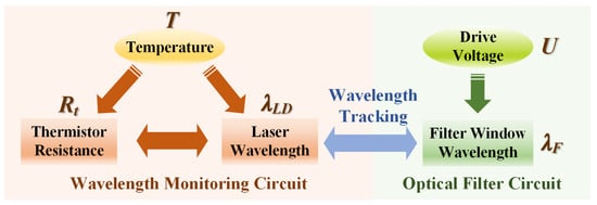
Figure 1.
Schematic description of the wavelength tracking system employing a thermistor monitoring circuit and a tunable optical filter.
3. Experimental Setup and Results
3.1. The Variation Curve of and as the Temperature Changes
In order to establish the relationship between the internal and operating temperature of the DFB-LD, an experiment is carried out, as shown in Figure 2. The and an external fixed-value resistor () are connected in series, with the supply voltage being . The voltage across is monitored using the analog-to-digital converter (ADC) module in a STM32 microcontroller, denoted as . Then, the resistance can be expressed as
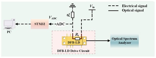
Figure 2.
Schematic diagram of the thermistor monitoring circuit.
After obtaining the relationship between and , the DFB-LD is placed in a temperature test chamber (GDW-100D, accuracy: 0.01 °C). The temperature is increased from −40 °C to 60 °C with a step of 5 °C, and the is recorded by Equation (3), which is shown in Figure 3. It is obvious that the and the temperature have an inverse relationship where increasing the temperature corresponds to decreasing . By utilizing the MATLAB (R2016B) curve fitting toolbox, the resistance–temperature fitted function is derived as Equation (4), which is given by
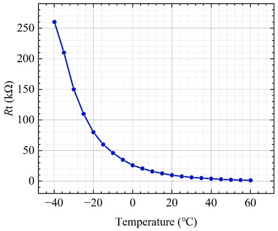
Figure 3.
The variation curve of the thermistor resistance as the temperature changes.
Additionally, an optical spectrum analyzer (MS9710C) is used to continuously record the under different temperature conditions. Simultaneously, the optical power of the DFB-LD () is measured by an optical power meter. The resulting variation curves of and varying with the temperature are presented in Figure 4, where the horizontal axis represents temperature, the primary vertical axis denotes , and the secondary vertical axis indicates . It shows the linear positive correlation between the and temperature, while the exhibits gradual attenuation, with a total reduction of 5.6 dB observed through the entire temperature variation. Similarly, the fitted function for the varying with temperature can be written as Equation (5) using the MATLAB curve fitting toolbox, as follows:
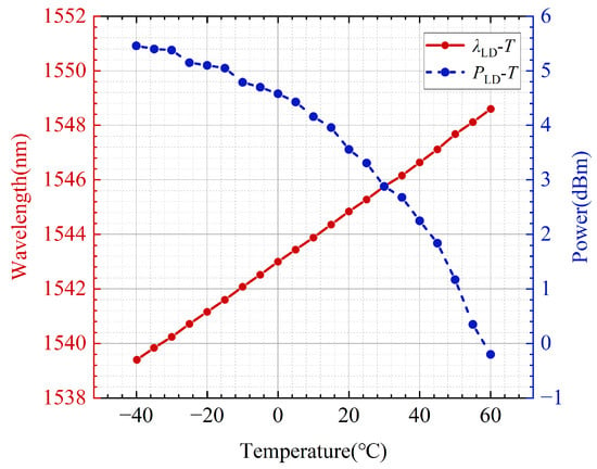
Figure 4.
Variation in DFB-LD center wavelength and output power with temperature.
3.2. The Variation Curve of the Varying with U and Temperature
The narrowband TOF employed in the experiment is an electronically controlled filter with a drive voltage range of 0 V to 45 V, with dimensions of 24.13 mm × 16.5 mm, as shown in Figure 5a. Firstly, the drive voltage of the TOF is set to a constant value, for example, 12 V. An erbium-doped fiber amplifier (EDFA) is used to provide a broadband light source. The transmission optical spectrum of the TOF is shown in Figure 5b. It can be seen that the filter window is located at approximately 1547.8 nm. The 3-dB bandwidth and insertion loss (IL) are 0.42 nm and 2.7 dB, respectively. Subsequently, the TOF is also placed in the temperature test chamber ranging from −40 °C to 60 °C with a step of 5 °C. The drive voltage is adjusted by the DAC module through the high-voltage module (DW-N501-10C32, 0–500 V) from 0 V to 45 V with a step of 2 V. The filter windows under different drive voltages and temperatures are recorded in Figure 6. It shows the variation characteristics of and U at different temperatures. Over the entire temperature range, the filter window varies from 1519.0 nm to 1550.0 nm. In other words, without considering the limitation on the wavelength fluctuation range of the DFB-LD, the system can achieve wavelength tracking within the range from 1519.0 nm to 1550.0 nm. In addition, it can be seen from Figure 6 that the is insensitive to the temperature, whereas a minor change in U can lead to relatively large-range drift of the . Based on such, we only consider the drive voltage as the parameter for controlling the filter window control in the following experiment. The fitted function for the varying with the U is expressed as Equation (6) using MATLAB curve fitting toolbox, which is given below:
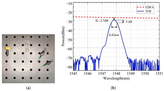
Figure 5.
(a) Photograph of the TOF. (b) Measured transmission optical spectrum of the TOF.
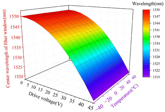
Figure 6.
The variation curve of the varying with U and temperature.
3.3. Wavelength Tracking System
By combining the wavelength monitoring circuit and the optical filter circuit, the complete wavelength tracking system is established. Figure 7 shows the structural diagram of the system. The output optical field of the DFB-LD enters the TOF, after which the optical power output by the filter is recorded using an optical power meter. Figure 8 presents the flowchart for the microcontroller control program. Firstly, based on the value measured from the thermistor monitoring circuit, the can be calculated using the fitted function in Equation (5). Secondly, let equal to , and the U can be consequently obtained according to Equation (6). Finally, by controlling the output of the high-voltage module through the microcontroller, the real-time tracking between the and the can be achieved.
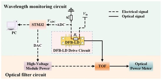
Figure 7.
Structural diagram of experimental setup for the wavelength tracking system employing a thermistor monitoring circuit and a tunable optical filter.
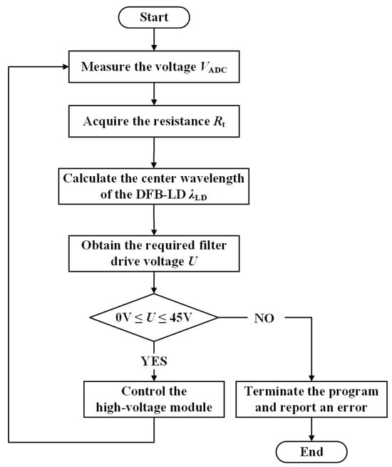
Figure 8.
Simplified flowchart of the microcontroller control program.
To verify the feasibility of our proposal, the DFB-LD is placed in the temperature test chamber. According to the experimental results above, the TOF exhibits an extremely low response to temperature variations. Therefore, the TOF is placed outside the temperature test chamber. The temperature is also set to range from −40 °C to 60 °C with a step of 5 °C. The output optical power after the TOF is recorded with and without wavelength tracking. With the wavelength tracking enabled, the output power maintains relative stability, shown as the red-dashed line in Figure 9a. It is important to note that due to the inherent power drift of the DFB-LD, the red-dashed-line power values exhibit a gradual 5.6 dB decrease as temperature increases. When the wavelength tracking is disabled, the synchronization between the filter window and the center wavelength of the DFB-LD is disrupted. For comparative testing, the drive voltage of the TOF is fixed at a constant value, for example, 20 V. That is, the center wavelength of the filter window is 1544.12 nm, currently, while the center wavelength of the DFB-LD will suffer from drift when the temperature changes. Only when the center wavelength of the DFB-LD matches the filter window of the TOF, the output optical power after the TOF reaches its maximum value, as shown by the blue solid line in Figure 9a. Moreover, Figure 9b shows a detailed view with temperature varying from 10 °C to 15 °C with a step of 0.5 °C. It indicates that when the temperature reaches 12.5 °C, the center wavelength of the DFB-LD coincides exactly with the filter window, causing the two curves to overlap at this point.
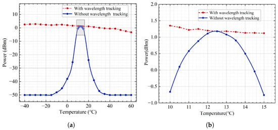
Figure 9.
(a) Output power fluctuation curves after TOF with/without wavelength tracking varying with temperature. (b) Detailed view of the two curves.
To further analyze and verify the effectiveness of the system, the blue-dashed curve in Figure 4 and the red-dashed curve in Figure 9a are plotted together, as shown in Figure 10a. It can be seen that the two curves maintain consistent trends, whose difference is shown in Figure 10b. There is a power difference of approximately 2.7 dB, which is the insertion loss of the TOF. These experimental results in Figure 10 fully validate both the feasibility of the proposed wavelength tracking system and its stability across the large temperature range.
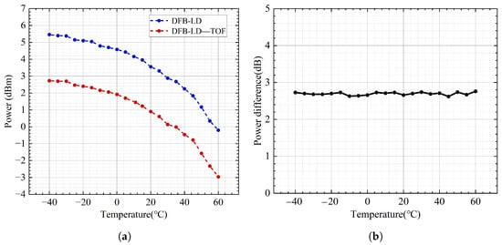
Figure 10.
(a) Output power fluctuation curves before and after the TOF as temperature changes. (b) Differential output optical power before and after the TOF.
The measurement resolution of the wavelength is defined as the minimum change that can be detected in the output center wavelength of the DFB-LD. In our system, the ADC module is utilized to detect the center wavelength of DFB-LD by the thermistor monitoring circuit. As a result, the measurement resolution is essentially determined by the minimum voltage change that can be acquired by the ADC module. When the temperature varies from −40 °C to 60 °C with a step of 5 °C, the center wavelength data of the DFB-LD versus the measured voltage by the ADC module are recorded, which are shown as the red dots in Figure 11a. The horizontal axis is , and the vertical axis is , and the blue solid line represents the fitted curve derived from these experimental data points, with its maximum slope calculated as . The sampling resolution of the ADC is 16 bit, which corresponds to a minimum voltage difference of . Therefore, the measurement resolution of the wavelength detection is <.
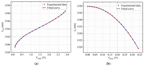
Figure 11.
(a) Relationship curve between and in the wavelength monitoring circuit as temperature changes. (b) Relationship curve between and in the optical filter link as temperature changes.
Similarly, the tracking control capability of this system is defined as the minimum change that can be controlled in the center wavelength of the filter window. As the temperature changes, the filter window data that can be controlled versus the output voltage of the DAC (denoted as ) are shown as the red dots in the Figure 11b. Likewise, the fitted curve derived from these experimental data points is represented by the blue solid line, with the on the abscissa and on the ordinate. The used DAC module is configured for 12-bit operation, resulting in a minimum step change of . In Figure 11b, the maximum slope is calculated as . Consequently, the minimum step of wavelength control is <.
4. Discussion
During the experiment, the overall system error is primarily attributed to the fitting errors associated with the thermistor resistance (), the DFB-LD wavelength (), and the TOF controlling (). The calculated values are determined to be , , and . Additionally, the primary uncertainty source of this system is the voltage control of the TOF. To evaluate the uncertainty, the STM32 microcontroller outputs a fixed 20 V drive voltage to the TOF under software control. Using the EDFA as the light source, the filter window is measured by the optical spectrum analyzer every one minute. The formula for Type A uncertainty is given as below [34]:
where s represents the standard deviation, n represents the number of measurements, represents the i-th measurement value, and represents the average of all these measurement values. Based on the calculation, the uncertainty evaluates to . The analysis of error and uncertainty validates the feasibility of effective tracking throughout the operating bandwidth.
This system enables dynamic adaptive tracking between the laser source and the optical filter, making it suitable for applications in lidar ranging [35] and free-space optical communication systems [18]. Current systems require active frequency stabilization for wavelength matching. This system eliminates the stringent stability requirement while maintaining precise matching at lower cost, demonstrating strong application potential.
As a whole, the set of results that we have presented confirm the viability of our approach. This work establishes a promising framework for wavelength tracking systems; however, it is subject to certain systematic limitations, particularly the insertion loss of the TOF and the power drift of the DFB-LD. To address these limitations, future research could employ low-loss, photonic, integrated circuit filtering modules to substantially reduce insertion losses at the physical level, and implement a feedback mechanism for real-time adjustment of the driving current.
5. Conclusions
We have proposed and experimentally demonstrated a broad-temperature-range wavelength tracking system employing a thermistor monitoring circuit and a tunable optical filter. In this system, the resistance of the thermistor integrated within the DFB-LD is detected in real-time by the thermistor monitoring circuit. The relationship curve among thermistor resistance, temperature, and center wavelength of the DFB-LD is established using an ADC module and an optical spectrum analyzer. The high-voltage module is regulated to drive the narrowband tunable optical filter. Furthermore, by combining with the curve of the filter window varying with the drive voltage, we have achieved real-time dynamic tracking between the filter window and the center wavelength of the DFB-LD. The experimental results demonstrate that our system can operate reliably over a broad temperature range of −40 °C to 60 °C, with wavelength tracking covering from 1539.4 nm to 1548.6 nm. Without considering the limitations of the laser’s center wavelength fluctuation, this system can achieve wavelength tracking across 1519.0 nm to 1550.0 nm. In addition, the wavelength detection resolution and the minimum step of wavelength control are better than 0.79 pm and 0.1 nm, respectively. Using the integrable and low-cost DFB-LD as the light source, the system takes full advantage of the corresponding relationship between the center wavelength of the DFB-LD and the thermistor resistance. This enables the real-time wavelength detection that can be achieved via a simple thermistor resistance monitoring circuit, significantly reducing the complexity of the system. As a result, the system effectively enhances the transmission stability and efficiency of laser sources in complex temperature environments, exhibiting substantial application potential in fields such as lidar and optical communications.
Author Contributions
Conceptualization, J.W., M.L. and H.L.; methodology, M.L. and H.L.; software, M.L., H.L. and X.S.; validation, J.W., C.M. and J.Y.; writing—original draft preparation, M.L. and H.L.; writing—review and editing, J.W., and J.Y.; supervision, J.W., J.Y. and C.M.; All authors have read and agreed to the published version of the manuscript.
Funding
This research was supported by the National Natural Science Foundation of China under Grant 62505217.
Institutional Review Board Statement
Not applicable.
Informed Consent Statement
Not applicable.
Data Availability Statement
The data presented in this study are available on request from the corresponding author.
Conflicts of Interest
The authors declare no conflicts of interest.
References
- Yoshida, M.; Katsuno, S.; Inoue, T.; Gelleta, J.; Izumi, K.; De Zoysa, M.; Ishizaki, K.; Noda, S. High-brightness scalable continuous-wave single-mode photonic-crystal laser. Nature 2023, 618, 727–732. [Google Scholar] [CrossRef]
- Zhou, R.; Zhang, Z.; Hong, M.H. The art of laser ablation in aeroengine: The crown jewel of modern industry. J. Appl. Phys. 2020, 127, 080902. [Google Scholar] [CrossRef]
- Kutscher, T.F.; Stock, C.; Sommer, F.; Jurkevicius, J.; Meyer, S.; Wiggert, M.; Lamminger, P.; Karpf, S. Broadband frequency-doubling of a swept-source laser from 1550 nm to 775 nm using a fan-out crystal and application in 2kHz LiDAR ranging. Opt. Express 2025, 33, 10637–10648. [Google Scholar] [CrossRef] [PubMed]
- Kautz, E.J.; Xu, A.; Harilal, A.V.; Polek, M.P.; Casella, A.M.; Senor, D.J.; Harilal, S.S. Influence of ambient gas on self-reversal in Li transitions relevant to isotopic analysis. Opt. Express 2023, 31, 3549–3564. [Google Scholar] [CrossRef] [PubMed]
- de Melo, Á.M.G.; Letellier, H.; Apoorva, A.; Glicenstein, A.; Kaiser, R. Laser frequency stabilization by modulation transfer spectroscopy and balanced detection of molecular iodine for laser cooling of 174Yb. Opt. Express 2024, 32, 6204–6213. [Google Scholar] [CrossRef]
- Song, J.; Qin, J.; Jin, P.; Chen, Y.; Su, J.; Lu, H. Realization of CW single-frequency tunable Ti:sapphire laser with immunity to the noise of the pump source. Opt. Express 2023, 31, 745–754. [Google Scholar] [CrossRef]
- Mannami, K.; Kondo, T.; Tsuno, T.; Miyashita, T.; Yoshida, D.; Ito, K.; Niizeki, K.; Nakamura, I.; Hong, F.-L.; Horikiri, T. Coupling of a quantum memory and telecommunication wavelength photons for high-rate entanglement distribution in quantum repeaters. Opt. Express 2021, 29, 41522–41533. [Google Scholar] [CrossRef]
- Atalar, A.; Margison, C.J.; Bayer, M.M.; Li, X.; Boyraz, O.B.; Boyraz, O. 3D coherent single shot lidar imaging beyond coherence length. Opt. Express 2024, 32, 40783–40793. [Google Scholar] [CrossRef]
- De Zoysa, M.; Sakata, R.; Ishizaki, K.; Inoue, T.; Yoshida, M.; Gelleta, J.; Mineyama, Y.; Akahori, T.; Aoyama, S.; Noda, S. Non-mechanical three-dimensional LiDAR system based on flash and beam-scanning dually modulated photonic crystal lasers. Optica 2023, 10, 264–268. [Google Scholar] [CrossRef]
- Zhang, S.; Li, M.; Chen, T.; Liu, Z.; He, J.J. Wavelength locking and parameter calibration method for V-cavity tunable modules. Opt. Express 2025, 33, 14129–14141. [Google Scholar] [CrossRef]
- Liu, Z.; Liu, S.; Wang, C.; Zhao, F.; Xing, W.; Xiong, C.; Zhu, L.; Ma, X. High-power distributed feedback laser diode arrays with narrow spectral width over a wide temperature range. Opt. Lett. 2024, 49, 3448–3451. [Google Scholar] [CrossRef] [PubMed]
- Zheng, Y.X.; Cui, J.M.; Ai, M.Z.; Qian, Z.H.; Cao, H.; Huang, Y.F.; Jia, X.J.; Li, C.F.; Guo, G.C. Large-tuning-range frequency stabilization of an ultraviolet laser by an open-loop piezoelectric ceramic controlled Fabry–Pérot cavity. Opt. Express 2021, 29, 24674–24683. [Google Scholar] [CrossRef] [PubMed]
- Zhao, W.; Zhou, X.; Shang, J.; Li, X.; Xiong, M.; Zhang, L.; Cao, Z.; Luo, H. Synchronous achievement of laser frequency stabilization and tunability via modulation transfer spectroscopy on the rubidium D1 line. Opt. Commun. 2025, 574, 131153. [Google Scholar] [CrossRef]
- Lai, Y.T.; Chen, Y.Y.; Chen, H.Z.; Yeh, C.H.; Lin, C.Y.; Chen, Y.Z.; Liao, C.Y.; Chang, D.C.; Chen, L.Y.; Chow, C.W. Stable wavelength-swept single-frequency erbium fiber laser in L-band tuning bandwidth. Phys. Scr. 2023, 98, 035514. [Google Scholar] [CrossRef]
- Yu, J.; Qin, Y.; Yan, Z.H.; Lu, H.D.; Jia, X.J. Improvement of the intensity noise and frequency stabilization of Nd:YAP laser with an ultra-low expansion Fabry-Perot cavity. Opt. Express 2019, 27, 3247–3254. [Google Scholar] [CrossRef]
- Ding, Y.; Tao, S.Q.; Wang, X.H.; Shang, C.L.; Pan, A.; Zeng, C.; Xia, J.S. Thermo-optic tunable optical filters with GHz-bandwidth and flat-top passband on thin film lithium niobate platform. Opt. Express 2022, 30, 22135–22142. [Google Scholar] [CrossRef]
- Fan, W.; Liu, B.; Jiang, Y. Study on dynamic wavelength matching technology of laser radar based on volume grating narrowband optical filtering. Infrared Laser Eng. 2022, 51, 20210639. [Google Scholar] [CrossRef]
- Li, Y.; Fernandes, G.; Benton, D.; Billaud, A.; Fernandes, M.; Patel, M.; Guiomar, F.; Ellis, A. Beaconless auto-alignment for single-wavelength 4.18 Tbit/s mode-division multiplexing free-space optical communications. J. Light. Technol. 2025, 43, 6029–6036. [Google Scholar] [CrossRef]
- Caro, L.; Dernaika, M.; Kelly, N.P.; Morrissey, P.E.; Alexander, J.K.; Peters, F.H. An Integration-Friendly Regrowth-Free Tunable Laser. IEEE Photonics Technol. Lett. 2018, 30, 270–273. [Google Scholar] [CrossRef]
- Huang, L.G.; Song, X.B.; Chang, P.F.; Peng, W.H.; Zhang, W.D.; Gao, F.; Bo, F.; Zhang, G.Q.; Xu, J.J. All-fiber tunable laser based on an acousto-optic tunable filter and a tapered fiber. Opt. Express 2016, 24, 7449–7455. [Google Scholar] [CrossRef]
- Li, Y.K.; Zhu, X.B.; Zhu, Y.B.; Yu, Y.F.; Dai, Y.S. Design of double closed-loop temperature control system with high stability for tunable laser. Transducer Microsyst. Technol. 2024, 43, 77–80. [Google Scholar] [CrossRef]
- Yan, Y.; Lv, C.Y.; Qi, M.; Lang, J.J.; Zhao, Y.S.; Wan, Z.L.; Lu, B.L.; Bai, J.T. Tunable multi-wavelength all polarization-maintaining hybrid mode-locked Yb-doped fiber laser. Opt. Commun. 2025, 574, 131069. [Google Scholar] [CrossRef]
- Sabbah, M.; Harrington, K.; Murphy, L.R.; Brahms, C.; Yerolatsitis, S.; Stone, J.M.; Birks, T.A.; Travers, J.C. Ultra-low threshold deep ultraviolet generation in a hollow-core fiber. Opt. Lett. 2024, 49, 3090–3093. [Google Scholar] [CrossRef] [PubMed]
- Shim, E.; Gil-Molina, A.; Westreich, O.; Dikmelik, Y.; Lascola, K.; Gaeta, A.L.; Lipson, M. Tunable single-mode chip-scale mid-infrared laser. Commun. Phys. 2021, 4, 268. [Google Scholar] [CrossRef]
- Suemura, Y.; Tajima, A.; Henmi, N.; Morimura, H.; Takahashi, H. Adaptive wavelength tunable optical filter employing an angle-tuned interference filter and an intelligent digital controller. J. Light. Technol. 1996, 14, 1048–1055. [Google Scholar] [CrossRef]
- Zheng, Z.; Yang, G.; Li, H.; Liu, X. Three-stage Fabry–Perot liquid crystal tunable filter with extended spectral range. Opt. Express 2011, 19, 2158–2164. [Google Scholar] [CrossRef]
- Liu, L.; Xue, W.; Jin, X.; Yue, J.; Yu, Z.; Zhou, L. Bandwidth and wavelength tunable all-optical filter based on cascaded opto-mechanical microring resonators. IEEE Photonics J. 2019, 11, 7800210. [Google Scholar] [CrossRef]
- Wang, C.; Li, X.; Zhang, S.; Yan, D.; Li, H. Wavelength and bandwidth tunable filter and its application in a dissipative soliton fiber laser. Opt. Lett. 2022, 47, 2698–2701. [Google Scholar] [CrossRef]
- Fan, Y.; He, Z.; Xia, H.; Lv, Y.; Yuan, W.; Dai, P.; Zhang, J.; Sun, Z.; Wang, F.; Shi, Y.; et al. Ultrawideband precise tunable wavelength-locked laser based on high-density integrated distributed feedback laser array. Opt. Express 2025, 33, 31801–31818. [Google Scholar] [CrossRef]
- Nunoya, N.; Ishii, H.; Kawaguchi, Y.; Iga, R.; Sato, T.; Fujiwara, N.; Oohashi, H. Tunable distributed amplification (TDA-) DFB laser with asymmetric structure. IEEE J. Sel. Top. Quantum Electron. 2011, 17, 1505–1512. [Google Scholar] [CrossRef]
- Wang, H.; Yu, Y. New theoretical model to analyze temperature distribution and influence of thermal transients of an SG-DBR laser. IEEE J. Quantum Electron. 2012, 48, 107–113. [Google Scholar] [CrossRef]
- Borràs, R.; del Río, J.; Oriach, C.; Juliachs, J. Study of a single emitter laser diode: Pspice model and characterization system. In Proceedings of the Semiconductor Lasers and Laser Dynamics VIII, Strasbourg, France, 22–26 April 2018; Volume 10682, p. 106821K. [Google Scholar]
- Ghadimi, A.; Alikhah, S. Simulation and analysis of dependence of threshold current and gain of λ/4 shifted DFB laser through transfer matrix. J. Opt. 2017, 46, 289–297. [Google Scholar] [CrossRef]
- Dorozhovets, M. Forward and inverse problems of Type A uncertainty evaluation. Measurement 2020, 158, 108072. [Google Scholar] [CrossRef]
- Fan, C.; Chen, C.; Liu, J.; Xie, Y.; Li, K.; Zhu, X.; Zhang, L.; Cao, X.; Han, G.; Huang, Y.; et al. Preliminary analysis of global column-averaged CO2 concentration data from the spaceborne aerosol and carbon dioxide detection lidar onboard AEMS. Opt. Express 2024, 32, 21870–21886. [Google Scholar] [CrossRef]
Disclaimer/Publisher’s Note: The statements, opinions and data contained in all publications are solely those of the individual author(s) and contributor(s) and not of MDPI and/or the editor(s). MDPI and/or the editor(s) disclaim responsibility for any injury to people or property resulting from any ideas, methods, instructions or products referred to in the content. |
© 2025 by the authors. Licensee MDPI, Basel, Switzerland. This article is an open access article distributed under the terms and conditions of the Creative Commons Attribution (CC BY) license (https://creativecommons.org/licenses/by/4.0/).