Article

Design of Hollow-Core Anti-Resonant Fibers Supporting Few Weakly Coupled Polarization-Maintaining Modes

1
Key Laboratory of Specialty Fiber Optics and Optical Access Networks, Shanghai University, Shanghai 200444, China
2
Institute of Fiber Optics, Shanghai University, Shanghai 201800, China
*
Author to whom correspondence should be addressed.
Photonics 2025, 12(10), 1018; https://doi.org/10.3390/photonics12101018
Submission received: 9 August 2025 / Revised: 11 October 2025 / Accepted: 14 October 2025 / Published: 15 October 2025
(This article belongs to the Section Optical Communication and Network)

Abstract

A nested semi-tube hollow-core anti-resonant fiber (HC-ARF) that can support the high-purity transmission of a few polarization-maintaining modes is designed in this paper. By employing bi-thickness hybrid silica/silicon anti-resonant tubes, the birefringence of the orthogonal polarized modes is significantly improved, and the weak coupling condition of the five lowest-order polarization maintaining modes, including the LP01_x, LP01_y, LP11a_x, LP11b_x, and LP11a_y, can be met. The effective refractive index difference between each pair of the supported adjacent modes is larger than 1.0 × 10⁻⁴. With hybrid multi-layer nested semi-tubes, the confinement losses of the supported modes are all less than 1.50 × 10⁻¹ dB/m within a transmission band from 1.530 to 1.620 μm. The minimum confinement losses of the LP01_y, LP01_x, LP11a_y, LP11a_x, and LP11b_x modes are 3.71 × 10⁻⁴ dB/m, 1.61 × 10⁻³ dB/m, 2.00 × 10⁻² dB/m, 1.30 × 10⁻¹ dB/m, and 4.20 × 10⁻² dB/m, respectively. Meanwhile, the unwanted higher-order modes are filtered out well to guarantee the modal purity. The minimum higher-order-mode extinction ratio of the lowest-loss LP21 mode to the highest-loss LP11 mode remains larger than 139 from 1.545 to 1.615 μm. The numerical results highlight the potential of the proposed polarization-maintaining few-mode hollow-core anti-resonant fibers in many application fields, such as short-range and high-capacity data transmission networks, fiber sensing systems, quantum communication systems, and so on.

1. Introduction

In recent years, networks with larger capacity and lower latency are in urgent demand with the rapid development of mobile communication and artificial intelligence, which presents a great challenge to the transmission performances of optical fibers. Hollow-core anti-resonant fibers (HC-ARFs) have attracted significant attention nowadays due to their unique properties for guiding light in air. Compared to traditional solid-core optical fibers, HC-ARFs have lower transmission losses [1,2,3], less optical nonlinearity [4], lower latency [5,6], lower waveguide dispersion [7], and higher laser damage thresholds [8]. These characteristics enable them to support the huge capacity of data transmission. Meanwhile, HC-ARFs can also be used in fields such as high-power laser delivery systems [9], optical sensing systems [10], terahertz wave transmission systems [11], laser micromachining systems [12], and so on.
At present, the transmission capacity of traditional solid-core single-mode fibers is close to the Shannon limit. Mode division multiplexing (MDM) has become an effective way to expand the capacity. In MDM systems, each mode in the few-mode fiber (FMF) is treated as an independent channel for the signal transmission. An FMF can also be realized using an HC-ARF. In 2020, Wang et al. reported a six-tube connected tube anti-resonant fiber (CT-ARF) with a core radius of 21 μm, which achieved a low-loss dual-mode transmission (LP01 and LP11) [13]. In 2024, Mahfuz et al. proposed a modified nested HC-ARF (M-NHCARF) structure with a core diameter of 55 μm. The fiber is capable of supporting more than 50 spatial modes with losses below 100 dB/km [14]. These studies show that a rational design of the cladding tubes is an effective strategy to control the modal transmission characteristics of HC-ARFs. However, there is a contradiction between the effective refractive index difference between the adjacent modes and the number of modes when only the MDM is employed. Another way to increase the number of modes is to utilize the combination of spatial modes and polarization maintenance modes, which are the two polarization states of multiple groups of hybrid vector modes. In 2017, Zhao et al. proposed a polarization-maintaining FMF with a highly doped elliptical core, capable of supporting 14 modes over a 75 nm bandwidth [15]. In 2018, Xia et al. introduced an air-hole-assisted polarization-maintaining FMF also based on a highly doped core, which can support up to 16 modes within a 55 nm bandwidth [16]. In 2019, Corsi et al. designed an elliptical-core FMF that supports 10 modes with a core refractive index of 1.455 and a bandwidth of 35 nm [17]. In 2021, Xie et al. presented a wheel-shaped ring-core FMF supporting 10 modes [18]. In 2022, Xue et al. proposed an air-hole-assisted polarization-maintaining FMF supporting 10 modes with a bandwidth of 80 nm [19].
The combination of MDM and polarization multiplexing provides a potential solution to break the bottleneck of communication capacity. Nevertheless, there are few studies on HC-ARFs that can support a few polarization-maintaining modes. One possible reason is that the birefringence of the orthogonally polarized vector modes is very small in HC-ARFs, and the requirement of weak coupling cannot be satisfied. In this work, we propose an HC-ARF with a hybrid nested semi-tube geometry to support five weakly coupled polarization-maintaining modes (LP01_x, LP01_y, LP11a_x, LP11a_y, and LP11b_x) for the first time, to the knowledge of the authors. The effective refractive index difference between the supported adjacent modes is all larger than 1.0 × 10⁻⁴. The minimum confinement losses (CLs) of the LP01 mode are 3.71 × 10⁻⁴ dB/m for x-polarization and 1.61 × 10⁻³ dB/m for y-polarization, respectively. The minimum CLs for the LP11a_y, LP11a_x, and LP11b_x are 2.0 × 10⁻² dB/m, 1.3 × 10⁻¹ dB/m, and 4.2 × 10⁻² dB/m, respectively. The CLs of the supported modes are all less than 1.50 × 10⁻¹ dB/m within a transmission band from 1.530 to 1.620 μm. Meanwhile, the unwanted higher-order modes (HOMs), such as the LP21 modes, are efficiently suppressed by the core–cladding mode coupling, and the modal purities of the desired modes are guaranteed well. The bending performances and the fabrication feasibility of the proposed HC-ARFs are also discussed.

2. Fiber Structure and Design Method

Figure 1 presents the cross-section of the proposed nested semi-tube HC-ARF. The fourfold semi-tube HC-ARFs are shown to have a stronger negative curvature effect and a higher birefringence [20,21]. The gray region represents the thick silica wall of the fiber. Four three-layer nested semi-tubes form the actual cladding of the fiber, and the area within the four semi-tubes is the fiber core with a diameter of Dc. The outermost layer is a hybrid silica/silicon semi-tube, with a silica thickness of t1 in the horizontal direction and t2 in the vertical direction. The coated silicon films in the two orthogonal directions both have a thickness of t3. The diameters of the four outermost semi-tubes are denoted as Ds, and the distances between the hybrid silica/silicon tubes to the inner side of the thick silica wall are defined as S. The second layer consists of four silica anti-resonant semi-tubes, with a thickness of t4. It is shown in Figure 1 that the four distances between the first layer and the second layer of the nested semi-tubes are denoted as Z1, Z2, Z3, and Z4, respectively. The innermost layer consists of four anti-resonant circular tubes, with a diameter of D3. Their thickness are also set to be t4, which satisfies the anti-resonance condition as follows [22]:
t 4 = m 0 . 5 λ 2 n s i l i c a 2 n a i r 2
where λ is wavelength, and nsilica and nair are the refractive indices of silica and air, respectively. When the wavelength λ is set to be 1.550 μm and the anti-resonant order m is set to be 2, the anti-resonant thickness t4 is determined to be 1.150 μm [2,3,13]. Since the anti-resonant reflection prevents the modal field from overlapping with the core boundary of the HC-ARFs, the birefringence of the orthogonally polarized modes is very small when t1 = t2. A significant difference between t1 and t2 can place the two polarization states in a hybrid transmission band and result in high birefringence [21]. According to [23], t1 and t2 are set to be 0.930 μm and 1.410 μm, respectively. Unfortunately, the birefringence induced by the bi-thickness mechanism is still relatively weak, which is not sufficient to split the two generated polarization states into weakly coupled states. In this paper, a layer of silicon film is coated on the inner wall of the outermost semi-tube walls. The refractive index of silicon can be written as follows [24]:
n s i l i c o n = A + B L + C L 2 + D λ 2 + E λ 4
where L 1 / ( λ 2 λ 0 2 ) , λ is the wavelength, and λ0 = 0.168 µm. The constants in Equation (2) are A = 3.41696, B = 1.38497 × 10⁻¹, C = −1.3924 × 10⁻², D = −2.09 × 10⁻⁵, and E = −1.48 × 10⁻⁷. Therefore, nsilicon = 3.478 when λ = 1.550 µm. Similarly, the refractive index of silica can be obtained using the Sellmeier formula [25]:
n s i l i c a = 1 + 0.6961663 λ 2 λ 2 0.0684043 2 + 0.4079426 λ 2 λ 2 0.1162414 2 + 0.8974794 λ 2 λ 2 9.896161 2
Without loss of generality, the predetermined structure parameters of the proposed HC-ARF are listed in Table 1.
The commercial finite element solver COMSOL 6.1 is used for analysis and optimization. The computational domain was discretized using highly refined meshes, with element sizes of λ/4 in air regions and λ/6 in the cladding tubes. To ensure the accuracy and reliability of the simulation results, we added a 3 μm silica layer and an 8 μm perfectly matched layer (PML) to simulate the nearly infinitely thick silica cladding. HC-ARFs are a type of leaky waveguides. The CLs of the linearly polarized (LP) eigenmodes of HC-ARFs can be obtained via the imaginary part of the effective refractive index, neff [26]:
CL = 40 π Im n e f f / λ ln 10
where Im (neff) represents the imaginary part of the neff. Since in HC-ARFs, light is guided in air, the material loss can be neglected. Meanwhile, the surface scattering loss (SSL) of the HC-ARF is much lower than the CL [27]. Therefore, we used the CL for the analysis of the loss of the designed optical fibers. This method is widely used in the design of HC-ARFs and has been verified by experimental results [28,29]. The effective refractive index here represents the ratio of the longitudinal propagation constant β of an eigenmode to the wave number k0 in a vacuum:
n e f f = β / k 0
here, k0 = 2π/λ. To evaluate polarization-maintaining capability, birefringence (Bp) is introduced to characterize the phase velocity difference between each pair of orthogonally polarized degenerate modes:
B p = n e f f x n e f f y
where n e f f x and n e f f y are the effective indices for the x- and y-polarized degenerated modes, including the fundamental modes (LP01) and the higher-order modes (LP11a, LP11b, etc.).

3. Optimization of the Nested Semi-Tube HC-ARFs

3.1. Effect of the Thickness of the Silicon Film, t3

For an FMF-based MDM system, mode coupling is critical to performance. When the core modes are strongly coupled, multiple-input multiple-output (MIMO) equalization technology is required for demultiplexing. However, MIMO processing not only increases system complexity at the receiving end but also increases power consumption. In order to avoid MIMO processing, a weak coupling between modes is desired. Experimental results show that when the optical fiber transmission distance is over 100 m, an effective refractive index difference (Δneff) beyond 1 × 10⁻⁴ is required for weak coupling between modes [30].
Figure 2a shows the variation of the birefringence (Bp) and the refractive indices of x- and y-polarized fundamental modes (FMs) with t3. The results show that t3 has a greater impact on the x-polarized FM. As t3 increases from 10 nm to 50 nm, the neff of the x-polarized FM gradually rises. When t3 = 50 nm, the x-polarized FM strongly couples with the surface mode of the hybrid cladding tube in the horizontal direction, leading to a drastic variation in the effective refractive index. The field distributions with no coupling (t3 = 10 nm) and with strong coupling (t3 = 50 nm) are compared in the inset of Figure 2a. In contrast, the neff of the y-polarized mode increases slowly with the increase in t3, and no avoidance coupling is observed. When t3 is between 10 nm and 70 nm, the values of Bp are all larger than 1 × 10⁻⁴. Figure 2b illustrates the variation of CLs of the two orthogonally polarized FMs with t3. Both modes experience an initial decrease in loss, followed by an increase as t3 continues to grow. To avoid mode coupling and minimize the CLs of FMs, t3 is set to be 30 nm. As shown in Figure 2b, the loss induced by the material loss of silicon (~0.2 dB/cm) accounts for a very small part of the total CL since the thickness of the silicon film is thin. The influence of the silicon material itself and its thickness variation on the losses of the HC-ARF can be neglected in the following simulations. However, if the silicon layer introduces other losses besides the material loss, the loss of the silicon layer may exceed the CL of the HC-ARF and become the main source of loss. This is beyond the scope of discussion in this article, and we do not take it into consideration.
Figure 3a compares the variation of the birefringence of the FMs with the wavelength of the proposed HC-ARF with and without the silicon films. It is shown that BP is about 4.5 × 10⁻⁵ when only the hybrid transmission band mechanism is used and the weak coupling condition of the two orthogonally polarized FMs is not met. The value of BP can be improved to greater than 1 × 10⁻⁴ when a layer of high refractive index silicon film is coated (t3 = 30 nm). Since the mechanism of birefringence in HC-ARFs comes from the difference in coupling between the core mode and the cladding mode in different polarization states, it can be predicted that this situation will also occur for the higher-order modes, which can be verified in the numerical simulation results below. Figure 3b depicts the CLs of the two polarized FMs. The loss of the y-polarized FM of the HC-ARF with silicon films is significantly lower than that of the HC-ARFs without silicon films, while the CL of the x-polarized FM increases when silicon films are added.

3.2. Effect of the Diameter of the Fiber Core, Dc

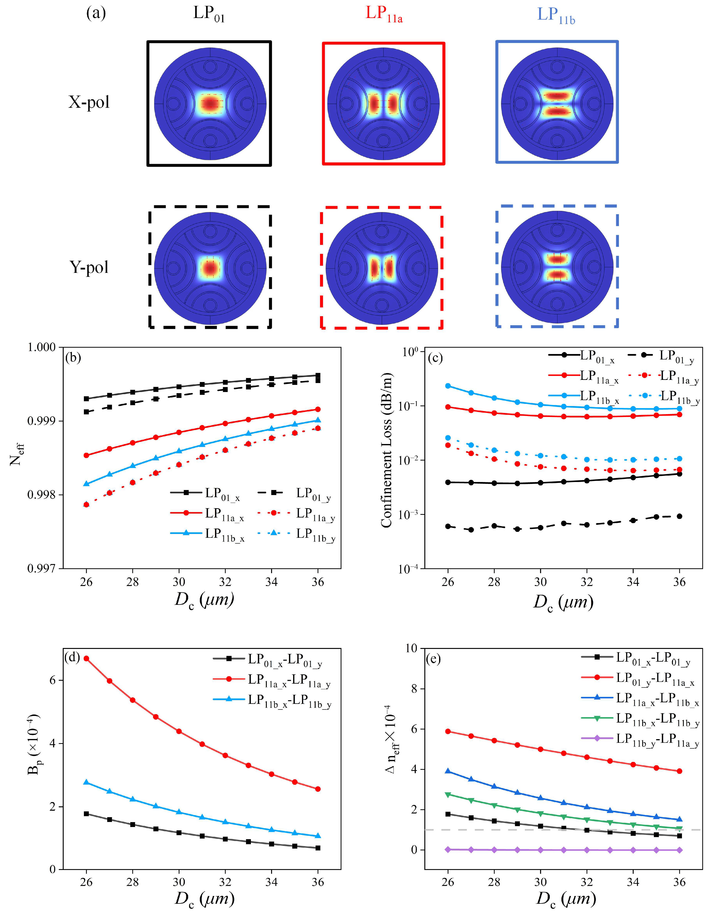
Apart from the polarization degeneration splitting, the weak coupling condition between different spatial modes should also be guaranteed. In this paper, few-mode HC-ARFs that can support the polarization-maintaining LP01 modes and LP11 modes are designed. In HC-ARFs, the effective refractive index differences between different spatial modes are determined by the diameter of fiber core Dc. The desired modes in our work are the two fundamental modes (LP01) and the first four higher-order modes (LP11), as shown in Figure 4a. Figure 4b illustrates the variation of the values of neff of these modes when the core diameter Dc increases from 26 μm to 36 μm (t3 = 30 nm, S = 27.5 μm, Zi = 6 μm, i = 1, 2, 3, 4). It can be noticed that the number of neff of the LP11a_y is almost the same as that of the LP11b_y mode. The possible reason for this result is that the y-polarization modes can better satisfy the inhibitive coupling condition of the proposed HC-ARF. As a result, the LP11b_y mode is not considered a usable polarization-maintaining mode in the following. It is shown that the effective refractive indices of all modes increase with the expansion of the core diameter. The growth rates of the effective indices of the modes in the y-polarization direction significantly exceed those of their counterpart in the x-polarization direction, resulting in a gradual reduction in birefringence, as depicted in Figure 4d. It is demonstrated that the first high-order modes (LP11a and LP11b) have a larger birefringence than that of the fundamental modes. Therefore, the weak coupling condition can be maintained as long as the birefringence of the FMs is larger than 1 × 10⁻⁴. Figure 4c depicts the CLs of these modes. The CLs of the four LP11 modes decrease substantially as Dc grows, while the CLs of the two LP01 modes demonstrate a slight decrease. The reason for the abnormal increment in the CLs of the LP01 modes might be the weak coupling between the LP01 modes and some cladding modes, whose effective refractive indices are close to the upper limit of those of the LP01 modes. Figure 4e shows the effective refractive index differences between adjacent modes considering both the polarization and spatial distribution. They all gradually diminish with the increment in Dc. This phenomenon is similar to that which happens in traditional solid-core fibers. Since Δneff between adjacent modes must be larger than 1 × 10⁻⁴ to effectively avoid mode coupling, the value of Dc is chosen to be 27 μm when the CLs are also taken into account.

3.3. Effect of the Distance Between the First Layer of the Semi-Tube and the Thick Silica Wall, S

Unlike conventional solid silica fibers that rely on the total internal reflection for the light guidance, the guidance of HC-ARFs is primarily dependent on the anti-resonant reflection and the inhibited mode coupling. As a result, it is difficult to strictly define mode cutoff conditions for HC-ARFs. In general, the CLs of HOMs are larger, but the elimination of unwanted HOMs is always insufficient for a high-quality mode division multiplexing system. Obviously, the larger the CL ratio between an unwanted mode and a desired mode is, the higher the purity of the desired mode after a certain distance of transmission (purity refers to the power ratio between the desired mode and the unwanted mode). Experiments have shown that when the higher-order mode extinction ratio, which refers to the CL ratio of a HOM to a target mode, exceeds 100, HOM can be effectively filtered out [31]. In order to maintain high purity of target modes, a feasible method is to break the inhibited core–cladding mode coupling of undesired HOMs. When the neff of a core mode approaches that of a cladding mode, power transfer from the core mode to the cladding mode results in a significant CL of the core mode. The nested anti-resonant semi-tubes and circular tubes in the proposed HC-ARFs not only reduce the CLs of target core modes but also provide more freedom to break the inhibited core–cladding mode coupling of undesired HOMs. Considering that CLs of LP02 and LP31 modes are much higher than those of LP21 mode, this paper only studies the suppression of four LP21 modes (LP21a_x, LP21a_y, LP21b_x, and LP21b_y).
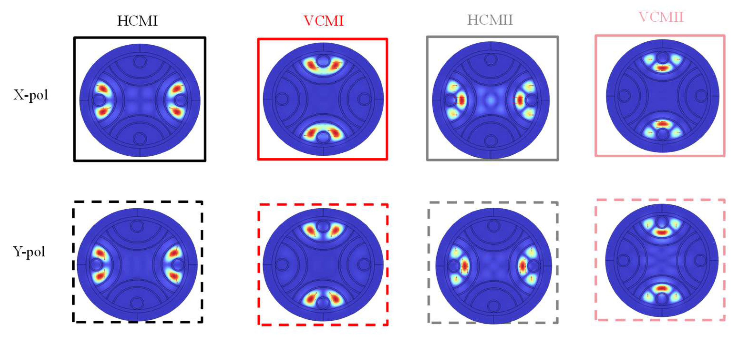
There are many leaky tube modes in the nested tubes of the cladding. Eight of them may have comparable effective refractive indices with those of the undesired HOMs. Figure 5 depicts their electrical fields, which are denoted as horizontal cladding modes (HCMI_x, HCMI_y, HCMII_x, and HCMII_y) and vertical cladding modes (VCMI_x, VCMI_y, VCMII_x, and VCMII_y), respectively. Here, HCMI_x, HCMI_y, HCMII_x, and HCMII_y represent x- and y-polarized horizontal cladding modes with field distributions primarily located in the horizontal gaps between the circular tubes and the second-layer semi-tubes. VCMI_x, VCMI_y, VCMII_x, and VCMII_y represent their vertical counterparts with energy confined in the vertical gaps. The tube modes whose fields are distributed between the first-layer and second-layer tubes can also affect the characteristics of the core modes. However, they cause extra losses for the first higher-order modes while filtering the HOMs. Therefore, we only consider the eight tube modes listed above. It is obvious that their effective refractive indices are determined by the gaps between the first-layer and second-layer semi-tubes.
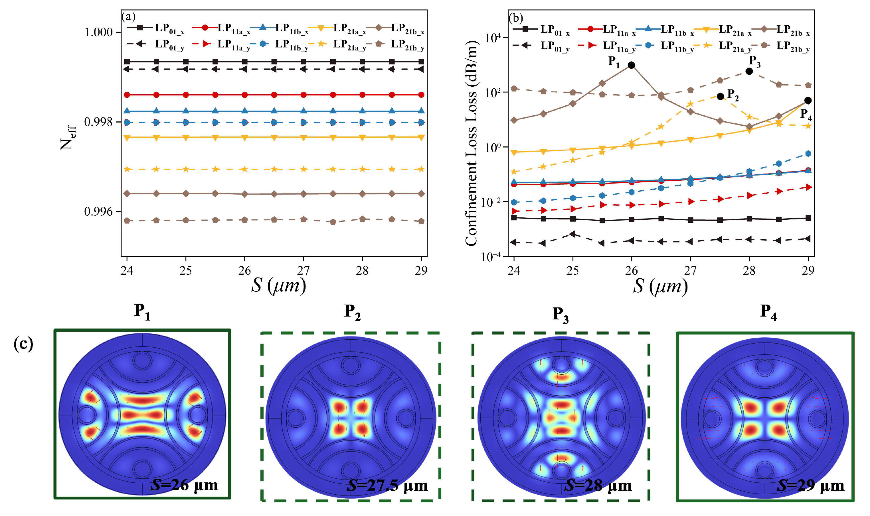
Figure 6 illustrates the variations of effective refractive indices and CLs of relative modes with the parameter S (Dc = 27 μm, t3 = 30 nm, Zi = 6 μm, i = 1, 2, 3, 4). As shown in Figure 6a, the effective refractive indices of x- and y-polarized core modes remain nearly constant. As depicted in Figure 6b, several coupling events between HOMs and cladding modes occur at different S values. When S = 26 μm, the x-polarized LP21b mode strongly couples with HCMI_x, resulting in increased loss. At S = 27.5 μm, HCMI_x couples with the y-polarized LP21a mode, leading to an increase in loss. For S = 28 μm, VCMII_y couples with the y-polarized LP21b mode, also increasing its loss. When S = 29 μm, HCMI_x and VCMI_y couple with the x-polarized LP21a mode, leading to an increase in loss. As S further increases, the CLs of the four LP11 modes gradually rise. Consequently, the distance between the first layer of the semi-tube and the thick silica wall S is set to be 27.5 μm in order to suppress the LP21 modes, and the CLs of the LP01 and LP11 modes are kept low.

3.4. Effect of Distance Between the Two Semi-Tube Layers, Zi

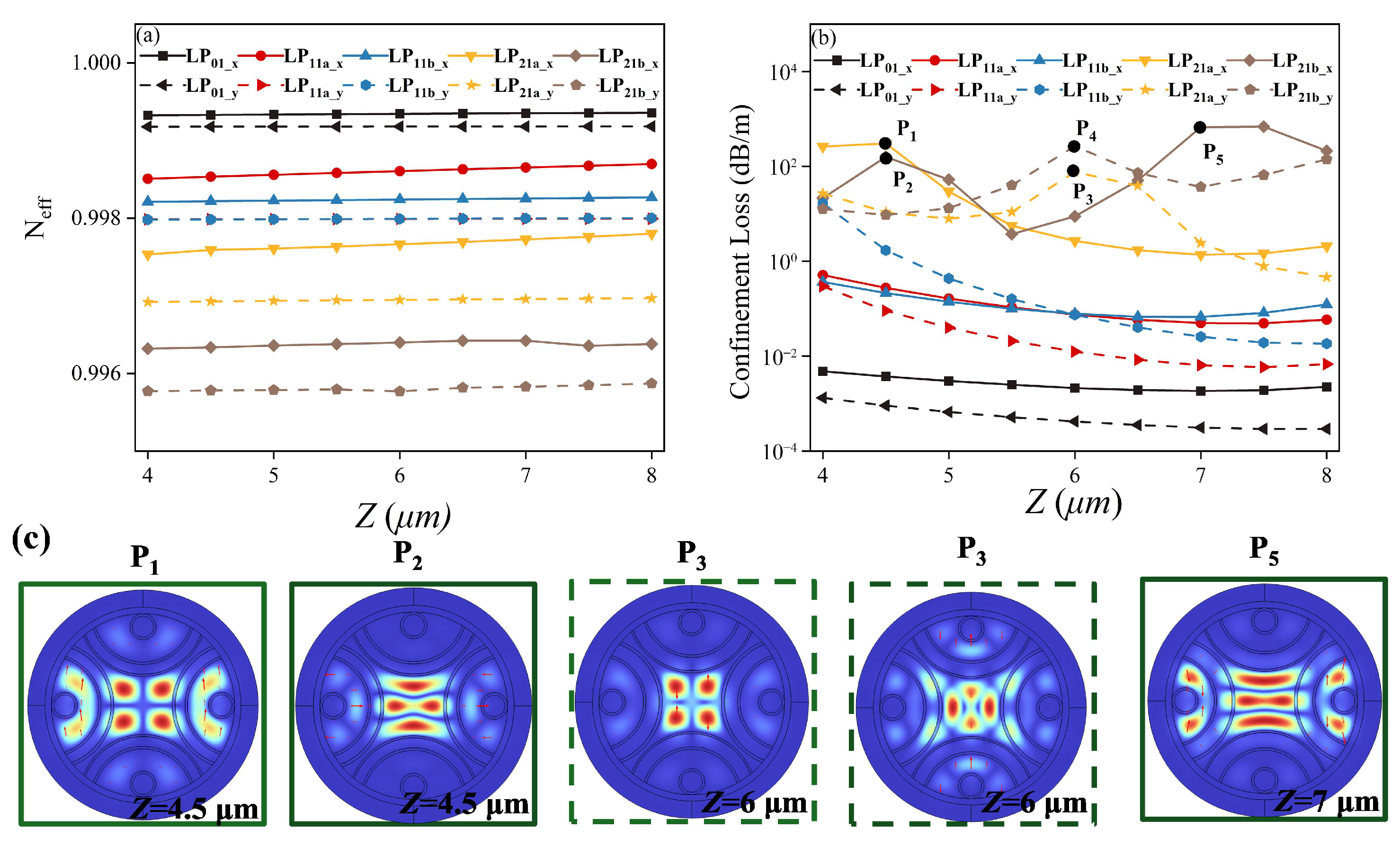
In this section, we investigate the influence of the four semi-tube gaps Zi, i = 1, 2, 3, and 4, as shown in Figure 1. To illustrate how core–cladding coupling works, the four gaps are initially set to be equal, denoted as Z. Figure 7a depicts the variations of the effective refractive indices of the relative modes with Z (t3 = 30 nm, S = 27.5 μm, Dc = 27 μm). It is shown that as Z increases, the effective refractive indices of some x-polarized core modes (LP11a_x and LP21a_x) show a significant rise, while those of the LP01_x and the LP11b_x modes experience minor changes. In contrast, the y-polarized core modes are only marginally affected by changes in Z, showing negligible variations in their effective refractive indices. Figure 7b illustrates the CLs of the relative modes. It is observed that when Z = 4.5 μm, LP21a_x couples with HCMI_y, resulting in increased loss. Meanwhile, HCMII_x couples with the x-polarized LP21b mode, also elevating its loss. When Z = 6 μm, HCMI_x and VCMII_y couple with the y-polarized LP21a and LP21b modes, respectively, and both modes have large CLs at this point. As Z = 7 μm, the CLs of x-polarized LP21b mode increase due to coupling with HCMI_y. Therefore, when Z is set to be 6 μm, the two y-polarized second-order modes can be filtered out well, but the two x-polarized second-order modes cannot be filtered out well. In order to ensure effective filtering of unwanted modes and low-loss transmission of wanted modes at the same time, we set the distances in the horizontal direction to different values, that is, Z1 = 6 μm and Z3 = 4.5 μm, respectively. The two distances in the vertical direction are both set to be 6 μm (Z2 = 6 μm and Z4 = 6 μm). All structure parameters of the proposed HC-ARF after optimization are listed in Table 2.

4. Transmission Characteristics of the Nested Semi-Tube HC-ARFs

4.1. Few-Mode Division Performances

Figure 8 depicts the transmission characteristics of the proposed HC-ARF. As shown in Figure 8a, the effective refractive indices of both x- and y-polarized modes decrease with increasing wavelength. Notably, the effective refractive indices of the LP11 modes exhibit a more significant reduction than those of the FMs. This is attributed to an anti-crossing coupling effect between the core modes and the surface modes of the hybrid silica/silicon tubes. Figure 8b illustrates the effective refractive index differences between adjacent modes. Due to the more rapid decrease in the effective refractive indices of the LP11 modes compared to those of the LP01 modes, the Δneff between the LP01_y mode and the LP11a_x mode increases with wavelength, consistent with the trend observed in Figure 8a. The effective refractive index differences among the LP01_x, LP01_y, LP11a_x, LP11b_x, and LP11a_y modes all exceed 1 × 10⁻⁴; thereby, the weak coupling condition required for a stable mode multiplexing is satisfied for the five supported modes. Figure 8c presents the CLs of the five supported modes. The lowest loss for LP01_y is 3.71 × 10⁻⁴ dB/m, while for the x-polarized LP01 mode, it is 1.61 × 10⁻³ dB/m. For the LP11a modes, the lowest losses are 2.0 × 10⁻² dB/m (y-polarized) and 1.3 × 10⁻¹ dB/m (x-polarized). Similarly, for the LP11b modes, the lowest losses are 8.3 × 10⁻² dB/m (y-polarized) and 4.2 × 10⁻² dB/m (x-polarized). However, due to strong coupling with the cladding modes, higher-order modes (e.g., LP21) exhibit significantly higher losses in the wavelength range from 1.530 to 1.620 μm. To quantify the suppression of higher-order modes, we define the minimum higher-order mode extinction ratio (MHOMER) as the ratio of the lowest loss of the LP21 modes to the highest loss of the LP11 modes. As shown in Figure 8d, MHOMER remains greater than 139 from 1.545 μm to 1.615 μm, ensuring high modal purity and efficient transmission of the wanted lower-order modes in both x- and y-polarized directions.

4.2. Bending Performances

This section investigates the effect of the bending radius on Neff and the bending loss of core modes. The bending losses (BLs) of HC-ARFs can be calculated by transferring the fiber bent along the x direction into an equivalent straight fiber [32]:
n e q x , y = n x , y 1 + x R b
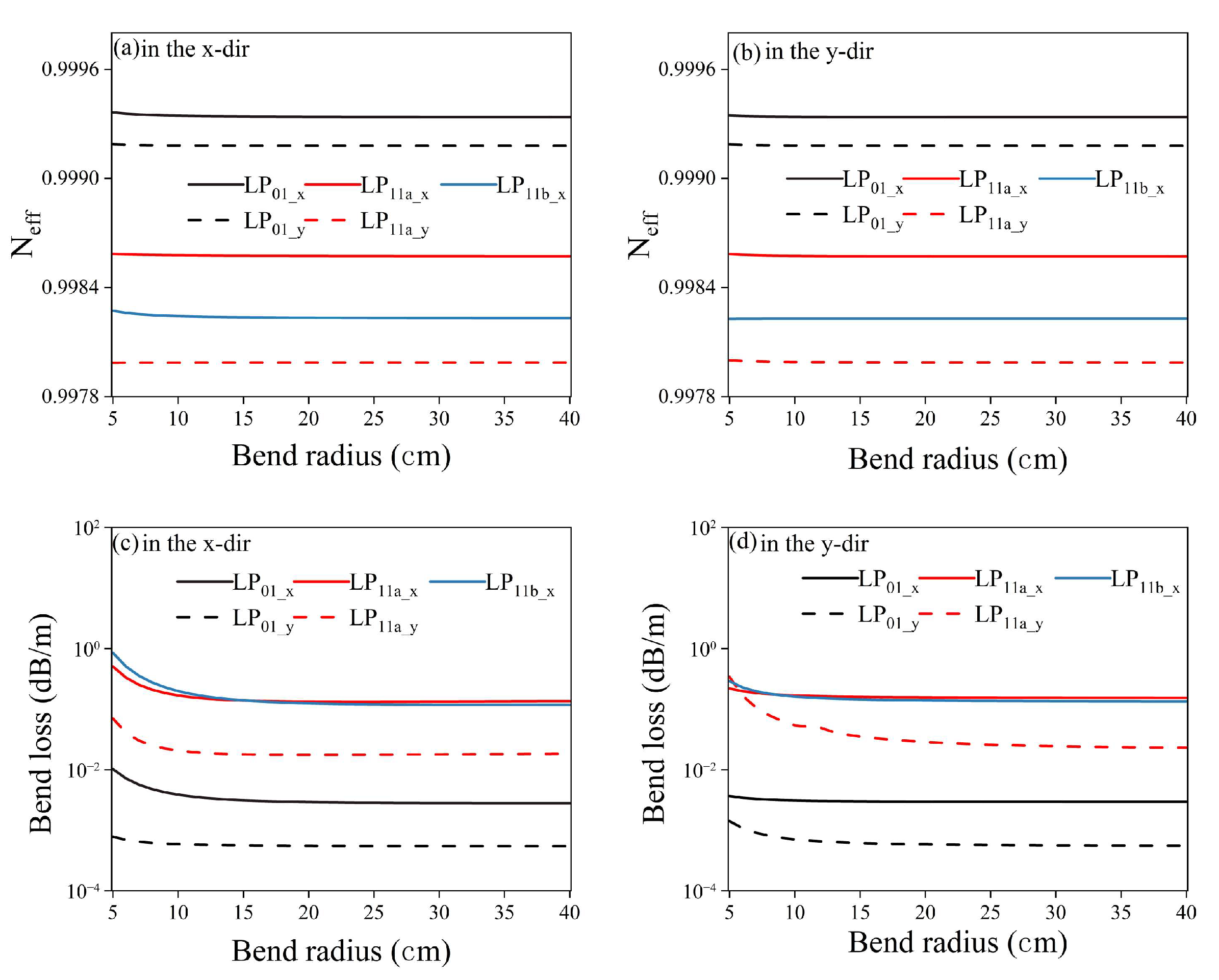
where Rb represents the bending radius. The refractive index distribution of the HC-ARF bent along the y direction can be similarly obtained. When the complex effective refractive index of the equivalent straight fiber is obtained, the BL can be calculated using Equation (4). Figure 9a,b depict the influence of the bending radius in different bending directions on the effective refractive indices of the LP01 and LP11 modes. As shown, the effective refractive indices of both modes remain essentially unchanged with varying bending radius. This indicates that the bending radius does not affect the weak coupling characteristics between adjacent modes. Figure 9c,d illustrate the bending losses of the core modes as a function of Rb. The bending loss decreases as Rb increases. In the x-bending direction, when Rb > 10 cm, the bending losses of all core modes converge to nearly constant values. Similarly, in the y-bending direction, the bending losses become essentially stable when Rb > 15 cm. It is worth noting that under x-direction bending, the x-polarized core modes are more significantly affected than the y-polarized core modes. Conversely, when the fiber is bent along the y-direction, the y-polarized core modes experience greater impact than their x-polarized counterparts.

5. Discussion

In the proposed HC-ARF with a hybrid nested semi-tube geometry, we use silicon as the high-refractive index material for the film coated on the inner side of the outermost semi-tube. Other materials with a high refractive index can also be used. However, silicon is more commonly used in optoelectronic devices working in the fiber communication band [33]. The silicon-coated HC-ARFs were fabricated using the high-pressure chemical vapor deposition method, which is a widely used silicon-core fiber manufacturing process [34]. The measured loss of the fabricated silicon-coated HC-ARF is approximately 20 times that of a pure silica HC-ARF [35]. Although in [35], the silicon film is coated in the post-processing step, the HPCVD can be used to coat the silicon film solely on the outermost capillaries. After coating the silicon film on the outermost tubes, a platform of precise laser cutting is required to prepare the semi-tubes [23]. The stack and draw method is then used to fabricate the preform of the HC-ARF. The feasibility of preparing a long length of silicon-coated HC-ARF has been recognized in the literature [36,37], but the realization of the process still needs to be investigated in the future.
Apart from experimental viability, the manufacturing tolerance of the semi-tube HC-ARFs should also be considered. Since the influence of the thickness of the silicon wall t3 has been discussed in Section 4.1, we only investigate the effect of the thickness of the anti-resonant tube t4 here.
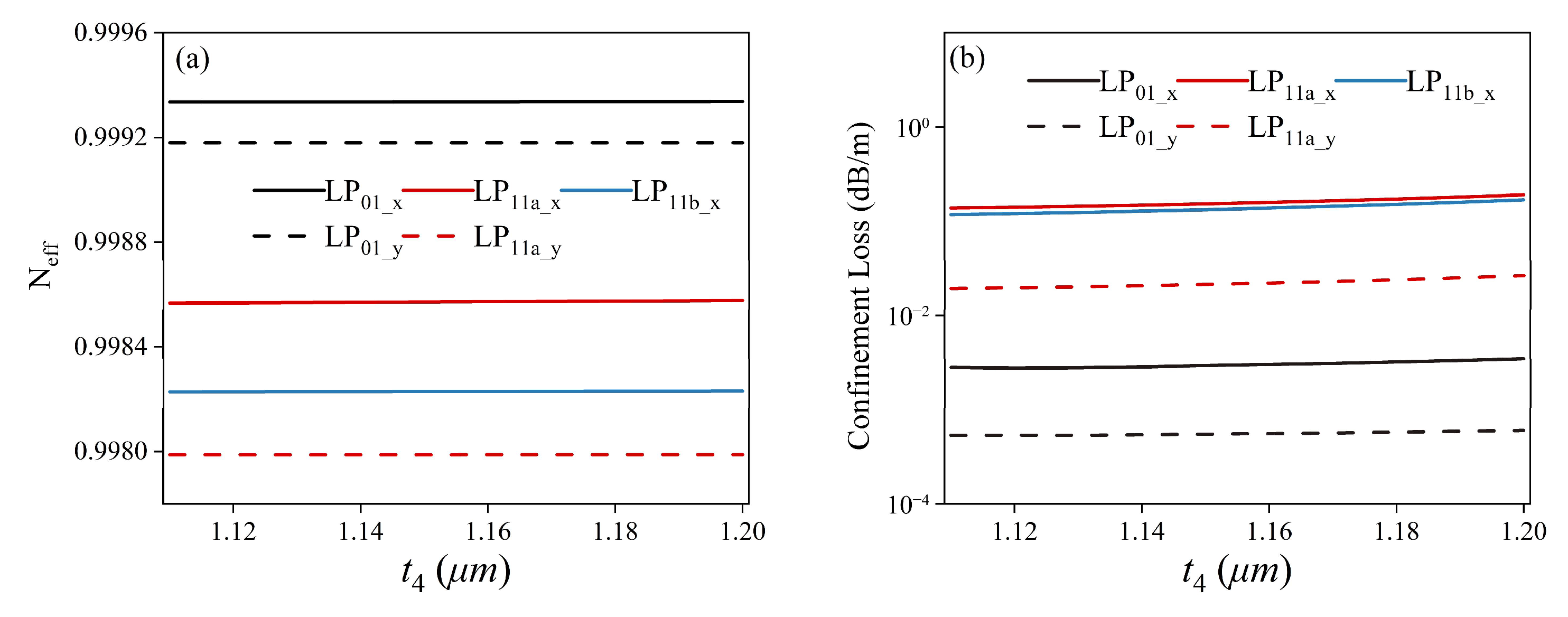
Figure 10a illustrates the trend of the effective refractive index of the core mode as a function of t4. The results indicate that the effective refractive index remains stable within this range, suggesting that fluctuations in t4 have a negligible effect on birefringence. Figure 10b presents the variation in confinement loss with t4, showing that when 1.11 μm < t4 < 1.20  μm, the loss remains nearly unchanged. The results show that the transmission characteristics of the modified semi-tube HC-ARF are less affected by the thickness of the walls of anti-resonant tubes.
The proposed polarization-maintaining few-mode HC-ARFs can support hybrid SDM and polarization multiplexing, which is promising for high-capacity, low-latency data transmission networks and other applications. Table 3 shows the performance comparison between the previously reported polarization-maintaining few-mode fibers and the HC-ARF we proposed. The HC-ARF proposed in this paper has advantages in terms of latency and bandwidth. We will further improve the performance of the proposed HC-ARFs in the future, such as the number of modes supported, the bandwidth, and so on.

6. Conclusions

We propose an HC-ARF with a hybrid semi-tube geometry that can support five weakly coupled polarization-maintaining modes (LP01_x, LP01_y, LP11a_x, LP11a_y, and LP11b_x). By coating a layer of high refractive index silicon film on the inner side of the outermost semi-tube, the designed HC-ARFs can ensure the effective index difference between each pair of the adjacent supported modes larger than 1 × 10⁻⁴, preventing intermodal coupling and supporting robust mode stability. The minimum CLs of the LP01_y, LP01_x, LP11a_y, LP11a_x, and LP11b_x modes are 3.71 × 10⁻⁴ dB/m, 1.61 × 10⁻³ dB/m, 2.00 × 10⁻² dB/m, 1.30 × 10⁻¹ dB/m, and 4.20 × 10⁻² dB/m, respectively. Furthermore, the hybrid semi-tube geometry of the HC-ARF can filter the unwanted high-order modes efficiently, and the MHOMER of the lowest-loss unwanted HOMs to the highest-loss wanted mode is larger than 139 from 1.545 to 1.615 μm. The proposed polarization-maintaining few-mode HC-ARFs can support the hybrid SDM and polarization multiplexing, which is promising in high-capacity and low-latency data transmission networks and other applications. We will further improve the performance of the proposed HC-ARFs in the future, such as the number of modes supported, the bandwidth, and so on. Meanwhile, since this work is a modeling one, the feasibility of fabrication will be investigated in the future.

Author Contributions

L.Z.: writing—original draft; J.C.: methodology, data curation; Y.X.: investigation. All authors have read and agreed to the published version of the manuscript.

Funding

Project 62275148 was supported by the National Natural Science Foundation of China; Project BE2022055-4 was supported by the Jiangsu Province’s Industry Outlook and Key Core Technologies.

Institutional Review Board Statement

Not applicable.

Informed Consent Statement

Not applicable.

Data Availability Statement

Data are contained within the article.

Conflicts of Interest

The authors declare no conflicts of interest.

References

  1. Debord, B.; Amsanpally, A.; Chafer, M.; Baz, A.; Maurel, M.; Blondy, J.M.; Hugonnot, E.; Scol, F.; Vincetti, L.; Gérôme, F.; et al. Ultralow transmission loss in inhibited-coupling guiding hollow fibers. Optica 2017, 4, 209–217. [Google Scholar] [CrossRef]
  2. Gao, S.F.; Wang, Y.Y.; Ding, W.; Jiang, D.-L.; Gu, S.; Zhang, X.; Wang, P. Hollow-core conjoined-tube negative-curvature fiber with ultralow loss. Nat. Commun. 2018, 9, 2828. [Google Scholar] [CrossRef]
  3. Zhu, Y.H.; Li, W.; Gao, F.Y.; Xu, X.; Song, N. Small-core hollow-core nested antiresonant nodeless fiber with simi-circular tubes. Opt. Express 2022, 30, 20373–20388. [Google Scholar] [CrossRef]
  4. Liu, Z.X.; Karanov, B.; Galdino, L.; Petrovich, M.N.; Richardson, D.J.; Poletti, F.; Slavik, R.; Bayvel, P.; Hayes, J.R.; Lavery, D.; et al. Nonlinearity-free coherent transmission in hollow-core antirenant fiber. J. Light. Technol. 2019, 37, 909–916. [Google Scholar] [CrossRef]
  5. Mukasa, K.; Takagi, T. Hollow core fiber cable technologies. Opt. Fiber Technol. 2023, 80, 103447. [Google Scholar] [CrossRef]
  6. Mesegure, A.C.; Bissessur, H.; Antona, J.C. Potential of hollow-core fibers for submarine systems. Opt. Fiber Technol. 2024, 84, 103750. [Google Scholar] [CrossRef]
  7. Hong, Y.; Bradley, D.; Taengnoi, N.; Bottrill, K.R.H.; Hayes, J.R.; Jasion, G.T.; Poletti, F.; Petropoulos, P.; Richardson, D.J. Hollow-core NANF for high-speed short-reach transmission in the S+C+L-bands. J. Light. Technol. 2021, 39, 6167–6174. [Google Scholar] [CrossRef]
  8. Zhu, X.Y.; Wu, D.K.; Wang, Y.Z.; Yu, F.; Li, Q.; Qi, Y.; Knight, J.; Chen, S.; Hu, L. Delivery of CW laser power up to 300 watts at 1080 nm by an uncooled low-loss antiresonant hollow-core fiber. Opt. Express 2021, 29, 1492–1501. [Google Scholar] [CrossRef]
  9. Cooper, M.A.; Wahlen, J.; Yerolatsitis, S.; Cruz-Delgado, D.; Parra, D.; Tanner, B.; Ahmadi, P.; Jones, O.; Habib, S.; Divliansky, I.; et al. 2.2  kW single-mode narrow-linewidth laser delivery through a hollow-core fiber. Optica 2023, 10, 1253–1259. [Google Scholar] [CrossRef]
  10. Liu, S.; Dong, X.L.; Cao, H.; Lv, J.; Zhao, L.; Xia, Y.; Wang, Y.; Lv, Z. Mid-infrared photothermal spectroscopy for breath Nitric Oxide testing with an anti-resonant fiber. Opt. Laser Technol. 2022, 152, 108158. [Google Scholar] [CrossRef]
  11. Hasanuzzaman, G.K.M.; Iezekiel, S.; Markos, C.; Habib, S. Hollow-core fiber with nested anti-resonant tubes for low-loss THz guidance. Opt. Commun. 2018, 426, 477–482. [Google Scholar] [CrossRef]
  12. Adamu, A.I.; Wang, Y.Z.; Correa, R.A.; Bang, O.; Markos, C. Low-loss micro-machining of anti-resonant hollow-core fiber with focused ion beam for optofluidic application. Opt. Mater. Express 2021, 11, 338–344. [Google Scholar] [CrossRef]
  13. Wang, Z.; Tu, J.J.; Liu, Z.Y.; Yu, C.; Lu, C. Design of Weakly Coupled Two-Mode Hollow-Core Antiresonant Fiber with Low Loss. J. Light. Technol. 2020, 38, 864–874. [Google Scholar] [CrossRef]
  14. Mahfuz, M.A.; Habib, M.S. Enhanced Inhibited Mode-Coupling: Multi-Mode Hollow-Core Anti-Resonant Fiber Designs. IEEE J. Sel. Top. Quantum Electron. 2024, 30, 1–9. [Google Scholar] [CrossRef]
  15. Zhao, J.J.; Tang, M.; Oh, K.; Feng, Z.; Zhao, C.; Liao, R.; Fu, S.; Shum, P.P.; Liu, D. Polarization-maintaining few mode fiber composed of a central circular-hole and an elliptical-ring core. Photonics Res. 2017, 5, 261–266. [Google Scholar] [CrossRef]
  16. Xiao, H.; Li, H.S.; Jian, S.S. Hole-assisted polarization-maintaining few-mode fiber. Opt. Laser Technol. 2018, 107, 162–168. [Google Scholar] [CrossRef]
  17. Corsi, A.; Chang, J.H.; Rusch, L.A.; LaRochelle, S. Design of Highly Elliptical Core Ten-Mode Fiber for Space Division Multiplexing With 2 × 2 MIMO. IEEE Photonics J. 2019, 11, 1–10. [Google Scholar] [CrossRef]
  18. Xie, Y.H.; Pei, L.; Zheng, J.J.; Zhao, Q.; Ning, T.; Li, J. Design of steering wheel-type ring depressed-core 10-mode fiber with fully improved mode spacing. Opt. Express 2021, 29, 15067–15077. [Google Scholar] [CrossRef]
  19. Xue, Y.B.; Li, H.S.; Liu, Y.J. Air hole-assisted polarization-maintaining few-mode fiber supporting 10 modes. Chin. J. Lasers 2022, 49, 1706001. [Google Scholar]
  20. Ding, W.; Wang, Y.Y. Hybrid transmission bands and large birefringence in hollow-core anti-resonant fibers. Opt. Express 2015, 23, 21165–21174. [Google Scholar] [CrossRef]
  21. Mousavi, S.A.; Sandoghchi, S.R.; Richardson, D.J.; Poletti, F. Broadband high birefringence and polarizing hollow core antiresonant fibers. Opt. Express 2016, 24, 22943–22958. [Google Scholar] [CrossRef] [PubMed]
  22. Yao, R.M.; Lai, Y.X. Design of a negative curvature hollow-core fiber for transmitting a single-mode dark hollow beam. Optik 2023, 288, 171147. [Google Scholar]
  23. Hong, Y.F.; Gao, S.F.; Ding, W.; Zhang, X.; Jia, A.Q.; Sheng, Y.L.; Wang, P.; Wang, Y. Highly birefringent anti-resonant hollow-core fiber with a bi-thickness fourfold semi-tube structure. Laser Photonics Rev. 2022, 16, 2100365. [Google Scholar] [CrossRef]
  24. Ran, J.J.; Meng, Y.C. Broadband high birefringence and single-polarization hollow-core anti-resonant fibers with an elliptical-like core. Opt. Commun. 2025, 575, 131251. [Google Scholar] [CrossRef]
  25. Malitson, I.H. Interspecimen comparison of the refractive index of fused silica. J. Opt. Soc. Am. 1965, 55, 1205–1209. [Google Scholar] [CrossRef]
  26. Xiao, Y.Y.; Cheng, J.Y. Design of a Nested Hollow-Core Anti-Resonant Fiber Sensor for Simultaneous Measurement of Temperature and Strain. Sensors 2024, 24, 7805. [Google Scholar] [CrossRef]
  27. Poletti, F. Nested antiresonant nodeless hollow core fiber. Opt. Express 2014, 22, 23807–23828. [Google Scholar] [CrossRef]
  28. Hong, Y.F.; Jia, A.Q.; Gao, S.F.; Sheng, Y.; Lu, X.; Liang, Z.; Zhang, Z.; Ding, W.; Wang, Y. Birefringent, low loss, and broadband semi-tube anti-resonant hollow-core fiber. Opt. Lett. 2023, 48, 163–166. [Google Scholar] [CrossRef]
  29. Stepniewski, G.; Dobrakowski, D.; Pysz, D.; Kasztelanic, R.; Buczyński, R.; Klimczak, M. Birefringent large-mode-area anti-resonant hollow core fiber in the 1.9 μm wavelength window. Opt. Lett. 2020, 45, 4280–4283. [Google Scholar] [CrossRef]
  30. Yaman, F.; Bai, N.; Zhu, B.Y.; Wang, T.; Li, G. Long distance transmission in few-mode fibers. Opt. Express 2010, 18, 13250–13257. [Google Scholar] [CrossRef]
  31. Uebel, P.; Gunendi, M.C.; Frosz, M.H.; Ahmed, G.; Edavalath, N.N.; Ménard, J.-M.; Russell, P.S. Broadband robustly single-mode hollow-core PCF by resonant filtering of higher-order modes. Opt. Lett. 2016, 41, 1961–1964. [Google Scholar] [CrossRef]
  32. Cai, M.Y.; Shi, W.H.; Lou, Y.; Gu, Y. Design and theoretical analysis of broadband bend-resistant low-loss anti-resonant fiber. Appl. Opt. 2024, 63, 5692–5698. [Google Scholar] [CrossRef]
  33. Wong, H. Recent developments in silicon optoelectronic devices. Microelectron. Reliab. 2002, 42, 317–326. [Google Scholar] [CrossRef]
  34. Kazanskiy, N.L.; Khonina, S.N.; Butt, M.A. Advancing frontiers: Semiconductor fibers in modern technology. Opt. Commun. 2024, 560, 130495. [Google Scholar] [CrossRef]
  35. Belardi, W.; Lucia, F.D.; Poletti, F.; Sazio, P.J. Composite material hollow antiresonant fibers. Opt. Lett. 2017, 42, 2535–2538. [Google Scholar] [CrossRef]
  36. Shaha, K.S.R.; Khaleque, A. Hollow core antiresonant fiber based polarizer and refractive index sensor. J. Light. Technol. 2024, 42, 907–913. [Google Scholar] [CrossRef]
  37. Hou, D.L.; Wang, X.; Lou, S.Q.; Sheng, Z. Dual-hollow-core anti-resonant fiber with silicon layers and nested resonant tubes for constructing a single-polarization 3 dB coupler. Opt. Express 2024, 32, 38780–38792. [Google Scholar] [CrossRef]
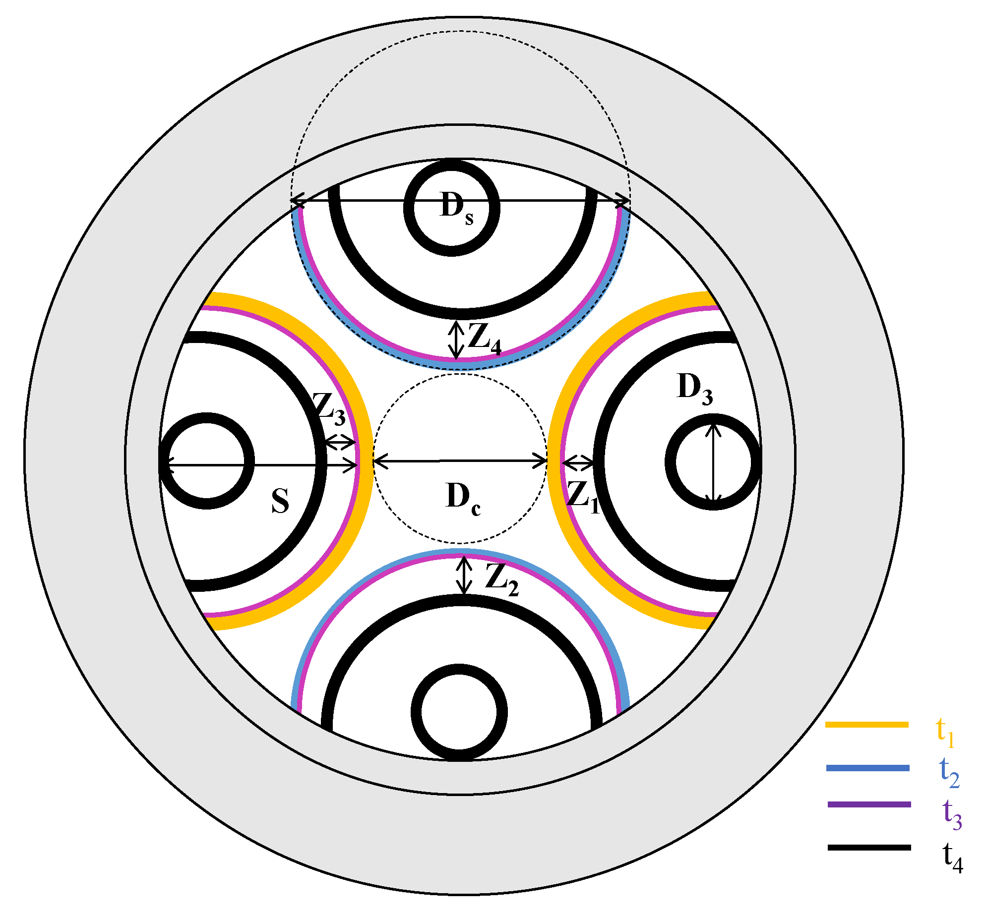
Figure 1. Cross-section of the nested semi-tube HC-ARF.
Photonics 12 01018 g001
Figure 2. (a) The variation of the effective refractive indices for x- and y-polarized FMs as a function of t3; (b) the variation of CLs with and without material loss for x- and y-polarized FMs as a function of t3.
Photonics 12 01018 g002
Figure 3. The variation of (a) the Bp and (b) CLs of the HC-ARFs as a function of wavelength when t3 = 0 nm and t3 = 30 nm.
Photonics 12 01018 g003
Figure 4. (a) Field distributions of the six lower-order modes; (b) the variation of the neff of each mode with of Dc; (c) the variation of the CLs of each mode with Dc; (d) the variation of the Bp for each pair of orthogonal polarized modes with Dc; (e) the variation of Δneff between each pair of adjacent modes with Dc.
Photonics 12 01018 g004
Figure 5. Electric field distributions of some relative cladding modes.
Photonics 12 01018 g005
Figure 6. (a) The variation of the values of neff of the ten lowest order polarization maintain modes with S; (b) the variation of the CLs of the ten lowest order polarization maintain modes with S; (c) the field distributions in the marked points when core–cladding mode coupling happens.
Photonics 12 01018 g006
Figure 7. (a) The variation of values of neff of the ten low-order modes with Z, (b) the variation of the CLs of the ten low-order modes with Z, (c) the field distributions in the marked points when core–cladding mode coupling occurs.
Photonics 12 01018 g007
Figure 8. (a) The variation of the values of neff of the ten low-order core modes with wavelength, (b) the variation of the values of Δneff between adjacent modes with wavelength, (c) the variation of CLs of the ten low-order core modes with wavelength, and (d) the values of the MHOMER with wavelength.
Photonics 12 01018 g008
Figure 9. (a) The variation of the values of neff of the five spatial modes with the bending radius in the x direction, (b) the variation of the values of neff of the five spatial modes with the bending radius in the y direction, (c) the CLs of the five spatial modes with the bending radius in the x direction, (d) the CLs of the five spatial modes with the bending radius in the y direction.
Photonics 12 01018 g009
Figure 10. (a) The variation of values of neff of the five spatial modes with t4; (b) the CLs of the five spatial modes with t4.
Photonics 12 01018 g010
Table 1. Predetermined parameters of the nested semi-tube HC-ARF.
Ds = 59.4 µmD3 = 12 µmt1 = 0.93 µm
t2 = 1.41 µmt4 = 1.15 µm
Table 2. Parameters of the semi-tube HC-ARF after optimization.
Dc = 27 µmDs = 59.4 µmD3 = 12 µm
S = 27.5 µmZ1 = 6 µmZ2 = 6 µm
Z3 = 4.5 µmZ4 = 6 µmt1 = 0.93 µm
t2 = 1.41 µmt3 = 0.03 µmt4 = 1.15 µm
Table 3. Performance comparison of PM few-mode fibers.
ReferencesncoreΔneffBandwidth (nm)
[17]1.455>1 × 10−435
[16]1.478>1 × 10−455
[19]1.460>1 × 10−480
This work1.000>1 × 10−490
Disclaimer/Publisher’s Note: The statements, opinions and data contained in all publications are solely those of the individual author(s) and contributor(s) and not of MDPI and/or the editor(s). MDPI and/or the editor(s) disclaim responsibility for any injury to people or property resulting from any ideas, methods, instructions or products referred to in the content.