Article

Designs of Time-Resolved Resonant Inelastic X-Ray Scattering Branchline at S3FEL

1
Institute of Advanced Light Source Facilities, Shenzhen 518107, China
2
State Key Laboratory of Chemical Reaction Dynamics, Dalian Institute of Chemical Physics, Chinese Academy of Sciences, Dalian 116023, China
*
Authors to whom correspondence should be addressed.
Photonics 2025, 12(10), 1009; https://doi.org/10.3390/photonics12101009
Submission received: 15 August 2025 / Revised: 22 September 2025 / Accepted: 11 October 2025 / Published: 13 October 2025
(This article belongs to the Special Issue Advances in X-Ray Coherent Imaging Technology)

Abstract

With the rapid development of X-ray free-electron lasers (XFELs), time-resolved resonant inelastic X-ray scattering (tr-RIXS) has attracted more attention. The preliminary designs of the tr-RIXS branchline and expected performance characteristics at the Shenzhen Superconducting Soft X-ray Free Electron Laser ( S 3 FEL ) are presented. A start-to-end simulation of the tr-RIXS branchline based on the 6-D phase space ray-tracing method of beamline simulation software package FURION was performed. The simulation design satisfies the key requirements of the tr-RIXS branchline, including spatial dispersion in the vertical dimension, temporal resolution, energy resolution, efficient utilization of SASE spectral photons, and spatial uniformity of the beam spot sizes across different wavelengths.

1. Introduction

Resonant inelastic X-ray scattering (RIXS) is predicated on the inelastic scattering processes that occur during X-ray-matter interactions [1]. This technique is characterized by tuning the incident X-ray photons to resonate with core-level transitions to valence or higher-lying electronic states. By analyzing the energy and momentum variations of the emitted RIXS photons, one can extract detailed information about the energy dispersion and momentum-resolved dynamics of electronic, spin, and lattice excitations in the material [2,3]. Time-resolved RIXS (tr-RIXS) typically employs pump laser pulses to perturb elementary or collective excitations in the sample, followed by the acquisition of RIXS signals at varying temporal delays to map the ultrafast evolution of these excitations [4]. With the development of XFELs [5,6,7,8,9], which can generate ultrashort X-ray pulses with a duration range from femtoseconds to attoseconds, the tr-RIXS technique has gradually attracted more attention [10]. Beye et al. reported the use o tr-RIXS on the experimental determination of the high-density and low-density liquid phase of silicon [11]. Dean et al. reported the use of tr-RIXS for experiments on the SR 2 Ir 4 to study subtle spin and charge dynamics [12,13]. Parchenko et al. reported the use of tr-RIXS for experimenting on different systems ranging from strongly correlated materials to catalysts [14]. These results demonstrate the power of tr-RXIS.
Current development objectives for tr-RIXS facilities based on XFEL primarily focus on advancing energy resolution, temporal resolution, and photon utilization efficiency as core performance metrics. The Heisenberg-RIXS (h-RIXS) system at the European XFEL employs a configuration combining a low line-density grating with an extended exit arm, achieving an energy resolution of 93 meV at 930 eV alongside a temporal resolution of 150 fs [15]. The SwissFEL-Furka experimental station enables efficient photon utilization within the SASE spectral bandwidth by implementing real-time monitoring of single-shot FEL incident spectra and scattered spectra, coupled with a spectral deconvolution algorithm to reconstruct a two-dimensional tr-RIXS spectrum [16]. Shenzhen Superconducting Soft X-ray Free Electron Laser ( S 3 FEL ) is a new light source under the design at the Institute of Advanced Light Source Facilities (IASF), Shenzhen [17]. The tr-RIXS branchline will be set in the FEL-1 beamline system at S 3 FEL [18]. To ensure the successful implementation of the tr-RIXS experiments, several beamline design requirements for tr-RIXS branchline are necessary [19]. The photons within the SASE spectral bandwidth should be utilized to the greatest extent possible. The maximized spatial dispersion in vertical dimension is necessary to generate sufficiently strong RIXS signals. The beam size needs to be smaller than 5 µm in the horizontal dimension. The pulse lengths should be shorter than 250 fs at the target energy including Cu L-edge (~930 eV), Ni L-edge (~867 eV), and Mn L-edge (~640 eV). The energy resolutions need to be greater than 30,000 at the target energy. To avoid mistakes in RIXS spectrum energy calibration, the beam sizes with different wavelengths at the sample plane need be maintained to be nearly consistent. In this paper, we present the preliminary designs of tr-RIXS branchline. To validate that the presented design fulfills the aforementioned design requirements of the tr-RIXS branchline, a start-to-end simulation of the design of beamline was carried out based on 6-D phase space ray-tracing method of beamline simulation software package FURION [20,21]. The pulse distributions at different locations, resolving power with different wavelengths, pulse length with different wavelengths, and the spectral intensity profiles across wavelengths proximal to the characteristic wavelength at the sample point are calculated.

2. Simulation Method Description

Before discussing the details of tr-RIXS branchline design, we introduce the simulation method in this section. The beamline simulation software package FURION was reported in our previous work [20,21] and a summarized description of the 6-D phase space ray-tracing method of FURION is presented in this section. Here we take the three-dimensional field source generated by Genesis 1.3 [22] as an example to describe how to create the geometric FEL source in the method. Genesis 1.3 generates a 3-D optical field E ( x , y , t ) , with the corresponding intensity distribution I ( x , y , t ) . We can obtain E ( θ x , θ y , v ) by performing a Fourier transform E ( x , y , t ) , with the corresponding intensity distribution I ( θ x , θ y , v ) . The distribution for the 6-D phase space geometric source can be described by the following:
P ( x , y , t ) = I ( x , y , t ) I ( x , y , t ) d x d y d t , P ( θ x , θ y , v ) = I ( θ x , θ y , v ) I ( θ x , θ y , v ) d θ x d θ y d v .
Various types of X-ray optics in the FURION include toroidal mirrors, spherical mirrors, cylindrical mirrors, elliptical cylindrical mirrors, ellipsoidal mirrors, toroidal gratings, spherical gratings, cylindrical gratings, planar gratings, toroidal varied-line-spacing (VLS) gratings, spherical VLS gratings, cylindrical VLS gratings, planar VLS gratings, and so on [20]. The schematic of 6-D phase space ray tracing through X-ray optics is shown in Figure 1. An arbitrary ray from source coordinate system O 1 x i n y i n t i n is traced along the path A 1 O A 2 to the image coordinate system O 1 x o u t y o u t t o u t . This ray can be described by vector V = ( x , θ x , y , θ y , t , v ) . ( x , θ x , y , θ y , t , v ) represents the deviations from the central ray, which lies along the primary optical axis O 1 O O 2 with the vector notation of V 0 = ( 0 , 0 , 0 , 0 , 0 , 0 ) .
The propagation of pulse can be divided into transverse (coordinate and divergence) and longitudinal (time and frequency) dimensions. The transverse components ( x , θ x , y , θ y ) can be obtained through direct ray tracing which is used in most ray-tracing software such as SHADOW [23], so we do not provide a detailed introduction here. The longitudinal components ( t , v ) can be described as follows:
t o u t = t i n + ( d 1 + d 2 | O 1 O | | O O 2 | ) / c , v o u t = v i n ,
where t o u t and v o u t are the time and frequency after propagation through optics, respectively; t i n and v i n are the time and frequency before propagation through optics, respectively. c is the speed of light; and d 1 and d 2 are the length of A 1 O and O A 2 , respectively. The simulation method of pulse propagating through free space is the same as that for propagating through optics in the 6-D phase space ray-tracing method. To compensate for the diffraction effect caused by slits and finite optics aperture, the hybrid method [24] is applied into the 6-D phase space ray-tracing method. The ray divergences are resampled after the slit and limited mirror size according to the angular profile calculated in the Fraunhofer diffraction approximation.

3. Tr-RIXS Branchline Design

3.1. The Optical Layout

The FEL-1 beamline aims to accommodate four endstations, which are the spectroscopy coherent imaging endstation (SCI), ambient-pressure X-ray photoelectron spectroscopy endstation (AP-XPS), multi-dimensional scattering endstation (MDS), and RIXS endstation. The FEL-1 operates in SASE mode with a photon wavelength from 1 nm to 3 nm. The preliminary optical layout of tr-RIXS branchline is presented in Figure 2. The optical path configuration differs between operational modes: In SASE mode, the path includes mirrors M4 and M5c but excludes mirror M3 and the planar variable-line-spacing (VLS) grating. Conversely, in monochromatic mode, the path includes M3 and G but excludes M4 and M5c. The plane offset mirror M1 is placed 169 m downstream of the source. M2 is a bendable mirror, located 179 m from the source point, and is used to compensate for the thermal deformation of M1 and to generate the horizontal focus.
The planar VLS grating monochromator (M3 and G) is placed 190.5 m downstream of the source to generate spatial dispersion of the beam spot and focus XFEL to sample point. Then the pulse is deflected to the tr-RIXS branchline by M6 at the distance 213 m from the source. The exit slit is set not to limit the pulse, which allows the full bandwidth of SASE pulse to project spatially dispersed photons onto the sample point. The pulse focused by the VLS grating in the vertical direction is reflected by the KB-v mirror at 362 m to position the focused beam spot at an optimum height for the tr-RIXS endstation experimental requirements. The curvature of the bendable KB-v mirror is set to infinity to avoid introducing aberrations in the vertical direction. Finally, the pulse is focused onto the sample point horizontally by KB-h mirror at 362.7 m. The main optics specifications of branchline design are shown in the Table 1. For the planar VLS grating G, the grooves are arranged perpendicular to the meridional direction. The grooves’ density is given by the following formula: n = n 0 ( 1 + b 2 M ) , where n 0 is the central groove density, b 2 is the VLS parameter, and M is the coordinate along the meridional direction. The n 0 and b 2 of G are 300 lines / mm and 2.13 × 10 5 mm 1 , respectively.

3.2. Start-to-End Simulation

To better analyze the feasibility of the design, we applied the 6-D phase space ray-tracing method to simulate XFEL pulse propagation through the beamline from the source to the tr-RIXS endstation in the monochromatic mode. In the simulation, the 6-D phase space SASE pulse was derived from a 3-D FEL optical field produced by Genesis 1.3. In the FEL simulation, the relevant simulation parameters are summarized in Table 2.
At the source point, the properties of the 3-D XFEL pulse are shown in Figure 3. Figure 3a shows the transverse–longitudinal ( y , t ) distribution of the XFEL pulse, where multiple longitudinal modes can be observed. Figure 3b shows the transverse-spectrum ( y , ε ) distribution of XFEL pulse, in which the multiple spikes in domain frequency (photon energy) can be observed. Figure 3c represents the transverse intensity distribution of the FEL pulse, which resembles a Gaussian distribution.
Now, we present the numerical simulation of the XFEL pulse through FEL-1 beamline to the tr-RIXS endstation. The simulation results are displayed at four locations: 191 m (after grating), 269 m (horizontal focus), 300 m (exit slit), and 365 m (sample point). Figure 4a–d are the transverse–longitudinal ( y , t ) distribution of XFEL pulse at four locations. After passing through the VLS grating, the XFEL pulse in ( y , t ) space exhibits pulse front tilt due to the angular dispersion and focusing effects of the VLS grating. The evolution of the pulse front tilt angle is observed during pulse propagation. Upon reaching the sample point, the pulse front tilt of the XFEL disappears and the photons with distinct energy components within the XFEL pulse are spatially dispersed along the y direction. At the sample point, the optical field distribution in y direction is essentially the spectrum of the XFEL pulse, and the pulse length is 71.28 fs. The optical field at the sample point inherently preserves the full spectral bandwidth of the SASE pulse due to the absence of exit slit constraints during pulse propagation. Figure 4e–h are the transverse intensity ( x , y ) of XFEL pulse at four locations. In the vertical dimension, the XFEL pulse is focused to the sample point. In the horizontal dimension, the XFEL pulse is initially focused to 269 m (horizontal focal point) after passing through bendable mirror M2 and is subsequently refocused onto the sample point after passing through the KB-h mirror. The intensity distribution at the sample point in the ( x , y ) domain indicates that there is spatial dispersion in the vertical dimension and that the beam size is smaller than 5 μ m in the horizontal dimension and approximately 4 mm in the vertical dimension.
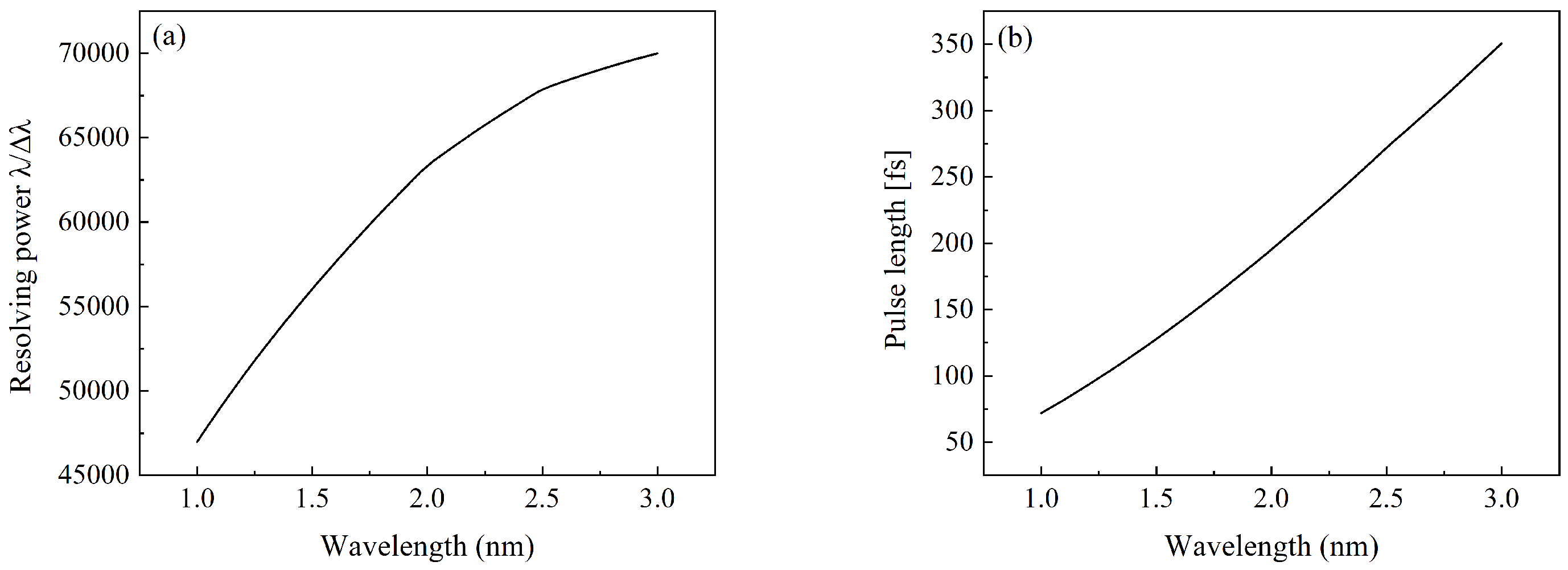
To confirm that our design fulfills the energy resolution and temporal resolution requirements essential for tr-RIXS experiments, we calculated the resolving power and pulse length at the sample point with different wavelengths based on 6-D phase space ray-tracing method. The resolving power was evaluated according to the Rayleigh criterion [25], which defines the minimum resolvable energy difference. Random figure errors with an RMS height error of 2 nm and an RMS slope error of 300 nrad in the meridional direction are introduced to all mirrors and grating within the optical path. The resolving power with different wavelengths is shown in Figure 5a, and the resolving power is much larger than 30,000. Although vibration, misalignment, and other tolerances affecting energy resolution were not explicitly incorporated into the simulation, the simulation results demonstrate that our beamline design retains sufficient intrinsic margins to satisfy the targeted energy resolution requirements of tr-RIXS experiment. The pulse length with different wavelengths is shown in Figure 5b. For targeted energy, the pulse lengths at the sample are 107.86 fs (Cu L-edge ~930 eV), 119.39 fs (Ni L-edge ~867 eV), and 186.44 fs (Mn L-edge ~640 eV). The simulation results conclusively confirm that our beamline design meets the stringent temporal resolution requirements essential for tr-RIXS experiments.
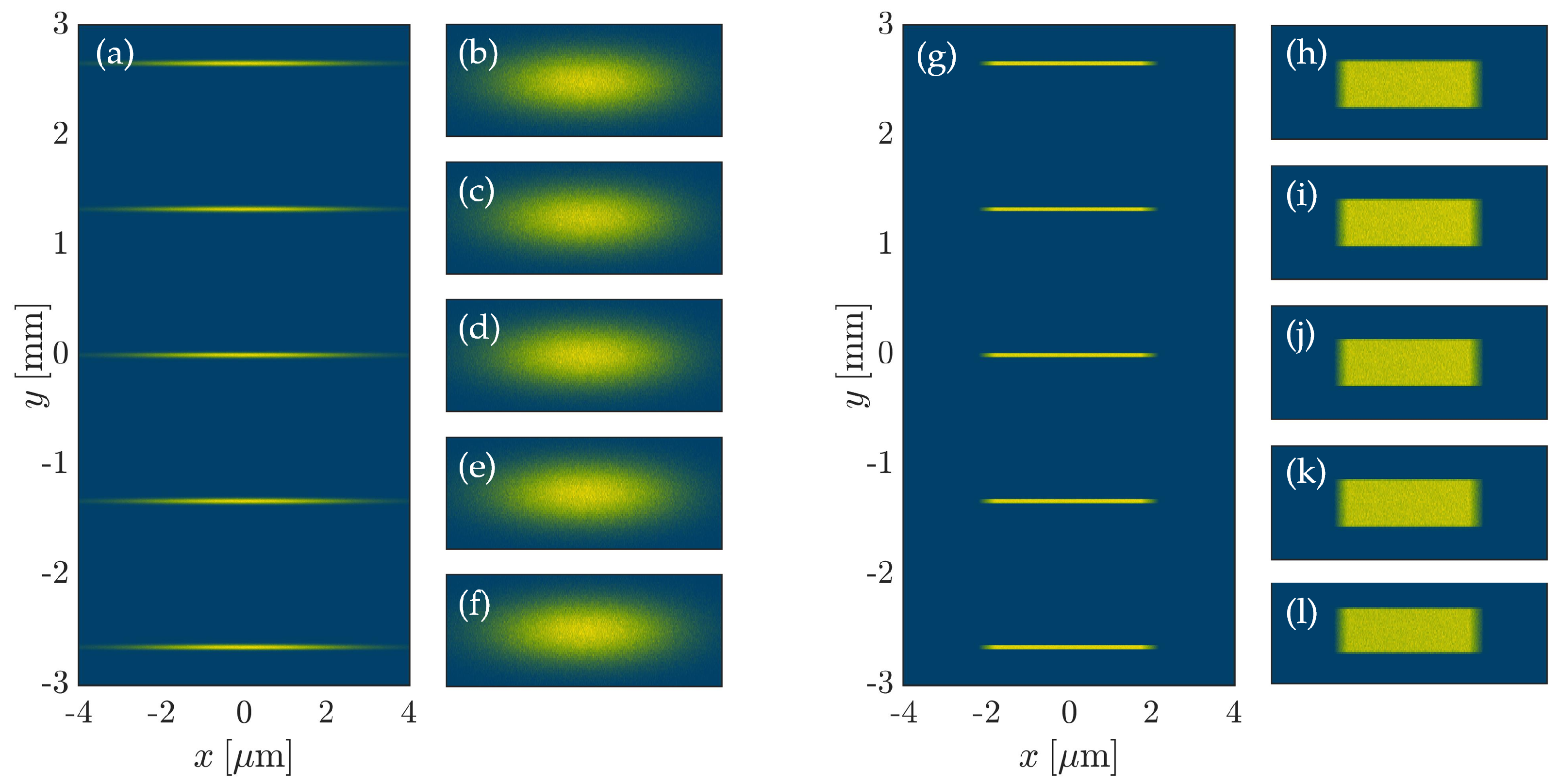
In the majority of RIXS beamline designs, a Wolter mirror is strategically employed to suppress chromatic aberrations in the dispersion dimension, thereby enforcing spatial uniformity of beam sizes across different wavelengths at the sample point and preventing erroneous energy calibration of RIXS spectrum. In our design, the focal point of the plane VLS grating is set at the sample point, and the curvature radius of the KB-v mirror is configured to infinity. The objective of this design is to achieve aberration avoidance in the dispersion direction, akin to the performance of Wolter mirrors. To verify that the beam sizes with different wavelengths at the sample point can be kept constant, we apply the ray-tracing method to simulate XFEL with different wavelengths propagation through the beamline. The simulation source is set to a geometric Gaussian source with a beam root-mean-square (rms) size σ x = σ y = 30.25 µm and a beam rms divergence θ x = θ y = 3 µrad. The center wavelength is set to 1 nm, the wavelength bandwidth of source is ± 0.15 % , and the step is 0.075 % . The intensity distributions with the wavelength from 1 nm × (1 − 0.15%) to 1 nm × (1 + 0.15%) at the sample point are shown in Figure 6b–f. Figure 6a is the integration of the intensity distributions of multiple wavelengths into a composite spatial–spectral map. The beam sizes in vertical dimension with the wavelength from 1 nm × (1 − 0.15%) to 1 nm × (1 + 0.15%) are 36.05 µm, 36.04 µm, 36.08 µm, 36.14 µm, and 36.23 µm. The relative variations of the beam sizes with different wavelength are less than 1%.
Although the intensity profile of the geometric Gaussian source closely approximates that of a SASE mode XFEL source, the inherent Gaussian intensity distribution may obscure optical aberrations introduced by beamline components. To rigorously demonstrate that such aberrations in our beamline design do not compromise the fidelity of RIXS experiments, a simulation with a geometric rectangular flat-topped source is presented. The source size is set to 70 µm× 70 µm ( H × V ) , and the source divergence is set to 7 µrad× 7 µrad ( H × V ) . The center wavelength is set to 1 nm, the wavelength bandwidth of the source is ± 0.15 % , and the step is 0.075 % . The intensity distributions with the wavelength from 1 nm × ( 1 0.15 % ) to 1 nm × ( 1 + 0.15 % ) at the sample point are shown in Figure 6h–l. Figure 6g integrates the intensity distributions of multiple wavelengths into a composite spatial–spectral map. The beam sizes in vertical dimension with the wavelength from 1 nm × ( 1 0.15 % ) to 1 nm × ( 1 + 0.15 % ) are 37.40 µm, 36.44 µm, 35.87 µm, 36.50 µm, and 37.54 µm. The relative variations of the beam sizes with different wavelength are less than 5%. As shown in Figure 6, the beams at different wavelengths exhibit negligible aberration in the vertical dimension while demonstrating minimal aberration in the horizontal dimension attributable to the KB-h mirror. The simulation results based on geometric Gaussian source and geometric rectangular flat-topped source demonstrate that our beamline design can achieve near-uniform beam sizes across multiple wavelengths at the sample point, thereby preventing erroneous energy calibration in RIXS spectrum analysis.

4. Discussion

The tr-RIXS beamline design at S 3 FEL successfully integrates a planar VLS grating monochromator with bendable KB mirrors to achieve simultaneous spatial dispersion, resolving power, temporal resolution, and spectral uniformity, which are critical for tr-RIXS studies. When benchmarked against the existing tr-RIXS beamline designs at other XFEL facilities, the beamline design presented in this work demonstrates significant advantages. Compared with the SwissFEL-Furka [16] and European XFEL-SQS [26] stations, our design achieves significant advantages in photon utilization and structural simplicity. As demonstrated in Figure 4h, the vertical dispersion efficiently separates SASE spectral components at the sample plane while maintaining a sub-5 µm horizontal and approximately 4 mm vertical focus. The optical synergy enables full SASE bandwidth utilization without exit-slit constraints, surpassing conventional Wolter-mirror designs in simplicity based on a VLS grating with its focus at the sample point and a KB-v mirror with an infinite curvature radius. Compared to the resolving power ~10,000 at 930 eV achieved by the European XFEL Heisenberg-RIXS facility [15], the beamline design in this work delivers higher energy resolution while maintaining enough temporal resolution. Temporal resolution, as shown in Figure 5b, confirms pulse durations below 250 fs at Cu/Ni/Mn L-edges, coupled with energy resolutions exceeding 30,000 across operational wavelengths, as shown in Figure 5a. Crucially, the results validates <5% beam size variation across wavelengths, as shown in Figure 6, eliminating chromatic aberrations that compromise RIXS energy calibration. In conclusion, the proposed tr-RIXS branchline design provides a robust foundation for ultrafast RIXS studies at S 3 FEL . With continued optimization and experimental validation, this beamline is poised to enable groundbreaking research on ultrafast dynamics in quantum materials, catalysts, and other complex systems.

5. Summary

The preliminary design of tr-RIXS branchline of FEL-1 at S 3 FEL was developed, and the 6-D phase space ray-tracing method was applied to characterize the performance metrics of our tr-RIXS branchline design. According to the simulations, our beamline design can fulfill the requirements of tr-RIXS branchline including comprehensive photon utilization within the SASE spectral bandwidth, the maximized spatial dispersion in the vertical dimension, beam size smaller than 5 µm in the horizontal dimension, pulse lengths shorter than 250 fs at target energy, energy resolution greater than 30,000 at target energy, and spatial uniformity of beam sizes across different wavelengths at the sample point. Our work provides great help for the FEL-1 beamline construction at S 3 FEL .

Author Contributions

Conceptualization, W.Z., Y.Z. (Yinpeng Zhong) and C.Y.; funding acquisition, C.Y.; investigation, W.S., K.H. and C.Y.; methodology, Y.Z. (Ye Zhu) and C.W.; software, W.S. and Y.W.; supervision, W.Z. and C.Y.; validation, W.S. and K.H.; writing—original draft, W.S.; writing—review and editing, Z.X., W.Z. and C.Y. All authors have read and agreed to the published version of the manuscript.

Funding

This work was supported by the Shenzhen Science and Technology Program (no. JCYJ20230807112409019), the National Natural Science Foundation of China (no. 12005135), the DICP (No. DICP I202304), the LiaoNing Revitalization Talents Program (grant No. XLYC2202030), and the Strategic Priority Research Program of the Chinese Academy of Sciences [no. XDB0970000 (subject: XBD0970100)].

Data Availability Statement

The raw data supporting the conclusions of this article will be made available by the authors on request.

Conflicts of Interest

The authors declare no conflicts of interest.

References

  1. de Groot, F.M.; Haverkort, M.W.; Elnaggar, H.; Juhin, A.; Zhou, K.J.; Glatzel, P. Resonant inelastic X-ray scattering. Nat. Rev. Methods Prim. 2024, 4, 45. [Google Scholar] [CrossRef]
  2. Kotani, A.; Shin, S. Resonant inelastic x-ray scattering spectra for electrons in solids. Rev. Mod. Phys. 2001, 73, 203. [Google Scholar] [CrossRef]
  3. Ament, L.J.; Van Veenendaal, M.; Devereaux, T.P.; Hill, J.P.; Van Den Brink, J. Resonant inelastic x-ray scattering studies of elementary excitations. Rev. Mod. Phys. 2011, 83, 705–767. [Google Scholar] [CrossRef]
  4. Chen, Y.; Wang, Y.; Jia, C.; Moritz, B.; Shvaika, A.M.; Freericks, J.K.; Devereaux, T.P. Theory for time-resolved resonant inelastic x-ray scattering. Phys. Rev. B 2019, 99, 104306. [Google Scholar] [CrossRef]
  5. Emma, P.; Akre, R.; Arthur, J.; Bionta, R.; Bostedt, C.; Bozek, J.; Brachmann, A.; Bucksbaum, P.; Coffee, R.; Decker, F.J.; et al. First lasing and operation of an ångstrom-wavelength free-electron laser. Nat. Photonics 2010, 4, 641–647. [Google Scholar] [CrossRef]
  6. Ishikawa, T.; Aoyagi, H.; Asaka, T.; Asano, Y.; Azumi, N.; Bizen, T.; Ego, H.; Fukami, K.; Fukui, T.; Furukawa, Y.; et al. A compact X-ray free-electron laser emitting in the sub-ångström region. Nat. Photonics 2012, 6, 540–544. [Google Scholar] [CrossRef]
  7. Milne, C.J.; Schietinger, T.; Aiba, M.; Alarcon, A.; Alex, J.; Anghel, A.; Arsov, V.; Beard, C.; Beaud, P.; Bettoni, S.; et al. SwissFEL: The Swiss X-ray free electron laser. Appl. Sci. 2017, 7, 720. [Google Scholar] [CrossRef]
  8. Zhu, Z.; Zhao, Z.; Wang, D.; Liu, Z.; Li, R.; Yin, L.; Yang, Z. SCLF: An 8-GeV CW SCRF linac-based X-ray FEL facility in Shanghai. In Proceedings of the FEL2017, Santa Fe, NM, USA, 20–25 August 2017; pp. 20–25. [Google Scholar]
  9. Decking, W.; Abeghyan, S.; Abramian, P.; Abramsky, A.; Aguirre, A.; Albrecht, C.; Alou, P.; Altarelli, M.; Altmann, P.; Amyan, K.; et al. A MHz-repetition-rate hard X-ray free-electron laser driven by a superconducting linear accelerator. Nat. Photonics 2020, 14, 391–397. [Google Scholar] [CrossRef]
  10. Bostedt, C.; Boutet, S.; Fritz, D.M.; Huang, Z.; Lee, H.J.; Lemke, H.T.; Robert, A.; Schlotter, W.F.; Turner, J.J.; Williams, G.J. Linac coherent light source: The first five years. Rev. Mod. Phys. 2016, 88, 015007. [Google Scholar] [CrossRef]
  11. Beye, M.; Sorgenfrei, F.; Schlotter, W.F.; Wurth, W.; Föhlisch, A. The liquid-liquid phase transition in silicon revealed by snapshots of valence electrons. Proc. Natl. Acad. Sci. USA 2010, 107, 16772–16776. [Google Scholar] [CrossRef]
  12. Dean, M.P.; Cao, Y.; Liu, X.; Wall, S.; Zhu, D.; Mankowsky, R.; Thampy, V.; Chen, X.; Vale, J.G.; Casa, D.; et al. Ultrafast energy-and momentum-resolved dynamics of magnetic correlations in the photo-doped Mott insulator Sr2IrO4. Nat. Mater. 2016, 15, 601–605. [Google Scholar] [CrossRef] [PubMed]
  13. Cao, Y.; Mazzone, D.; Meyers, D.; Hill, J.; Liu, X.; Wall, S.; Dean, M. Ultrafast dynamics of spin and orbital correlations in quantum materials: An energy-and momentum-resolved perspective. Philos. Trans. R. Soc. A 2019, 377, 20170480. [Google Scholar] [CrossRef] [PubMed]
  14. Parchenko, S.; Paris, E.; McNally, D.; Abreu, E.; Dantz, M.; Bothschafter, E.M.; Reid, A.H.; Schlotter, W.F.; Lin, M.F.; Wandel, S.F.; et al. Orbital dynamics during an ultrafast insulator to metal transition. Phys. Rev. Res. 2020, 2, 023110. [Google Scholar] [CrossRef]
  15. Gerasimova, N.; La Civita, D.; Samoylova, L.; Vannoni, M.; Villanueva, R.; Hickin, D.; Carley, R.; Gort, R.; Van Kuiken, B.; Miedema, P.; et al. The soft X-ray monochromator at the SASE3 beamline of the European XFEL: From design to operation. Synchrotron Radiat. 2022, 29, 1299–1308. [Google Scholar] [CrossRef]
  16. Tollerud, J.O.; Sparapassi, G.; Montanaro, A.; Asban, S.; Glerean, F.; Giusti, F.; Marciniak, A.; Kourousias, G.; Billè, F.; Cilento, F.; et al. Femtosecond covariance spectroscopy. Proc. Natl. Acad. Sci. USA 2019, 116, 5383–5386. [Google Scholar] [CrossRef]
  17. Wang, X.; Zeng, L.; Shao, J.; Liang, Y.; Yi, H.; Yu, Y.; Sun, J.; Li, X.; Feng, C.; Wang, Z.; et al. Physical design for shenzhen superconducting soft x-ray free-electron laser (s3fel). In Proceedings of the IPAC’23, Venice, Italy, 7–12 May 2023. [Google Scholar]
  18. Xu, Z.; Zhang, W.; Yang, C.; Zhong, Y. Shape optimization design of the offset mirror in FEL-1 beamline at S3FEL. Sci. Rep. 2023, 13, 9653. [Google Scholar]
  19. Zhong, Y.; Yang, X. Advances in free-electron-laser based scattering techniques and spectroscopic methods. Acta Phys. Sin. 2024, 73, 194101. [Google Scholar] [CrossRef]
  20. Zhu, Y.; Yang, C.; Hu, K.; Wu, C.; Luo, J.; Hao, Z.; Xing, Z.; Li, Q.; Xu, Z.; Zhang, W. FURION: Modeling of FEL pulses propagation in dispersive soft X-ray beamline systems. Opt. Express 2024, 32, 5031–5042. [Google Scholar] [CrossRef]
  21. Hu, K.; Xing, Z.; Yang, C.; Zhu, Y.; Wu, C.; Xu, Z.; Wang, Q.; Zhang, W. Modeling of X-ray pulse propagation in beamline systems using a 6D phase space ray-tracing method. J. Synchrotron Radiat. 2025, 32, 942–950. [Google Scholar] [CrossRef]
  22. Reiche, S. GENESIS 1.3: A fully 3D time-dependent FEL simulation code. Nucl. Instrum. Methods Phys. Res. Sect. A Accel. Spectrometers Detect. Assoc. Equip. 1999, 429, 243–248. [Google Scholar] [CrossRef]
  23. Sanchez del Rio, M.; Canestrari, N.; Jiang, F.; Cerrina, F. SHADOW3: A new version of the synchrotron X-ray optics modelling package. Synchrotron Radiat. 2011, 18, 708–716. [Google Scholar] [CrossRef]
  24. Shi, X.; Reininger, R.; Sanchez del Rio, M.; Assoufid, L. A hybrid method for X-ray optics simulation: Combining geometric ray-tracing and wavefront propagation. J. Synchrotron Radiat. 2014, 21, 669–678. [Google Scholar] [CrossRef]
  25. Sparrow, C.M. On spectroscopic resolving power. Astrophys. J. 1916, 44, 76. [Google Scholar] [CrossRef]
  26. Agåker, M.; Söderström, J.; Baumann, T.M.; Englund, C.J.; Kjellsson, L.; Boll, R.; De Fanis, A.; Dold, S.; Mazza, T.; Montaño, J.; et al. A 1D imaging soft X-ray spectrometer for the small quantum systems instrument at the European XFEL. Synchrotron Radiat. 2024, 31, 1264–1275. [Google Scholar] [CrossRef]
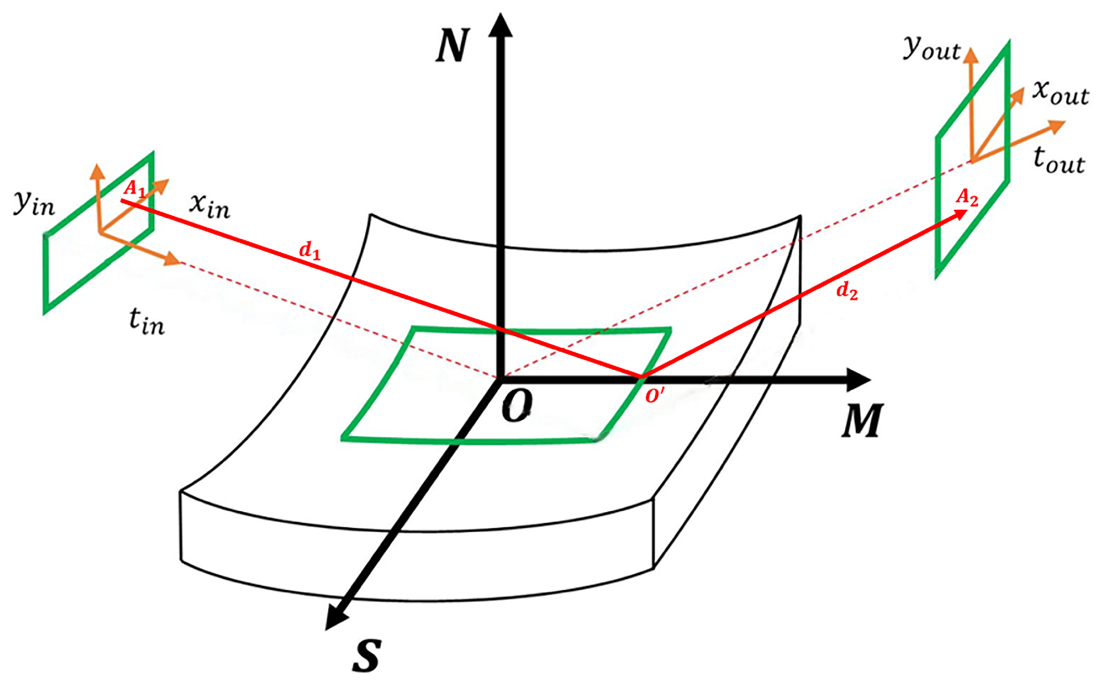
Figure 1. Schematic of 6-D phase space ray tracing through X-ray optics.
Photonics 12 01009 g001
Figure 2. The preliminary optical layout of tr-RIXS branchline of the FEL-1 beamline.
Photonics 12 01009 g002
Figure 3. The Properties of the 3-D XFEL source generated from Genesis 1.3. (a) Transverse–longitudinal ( y , t ) distribution of the pulse, (b) transverse-spectrum ( y , ε ) distribution of the pulse, and (c) transverse intensity ( x , y ) distribution of the pulse.
Photonics 12 01009 g003
Figure 4. Snapshots of a 3-D FEL pulse propagation in the beamline at different locations. (a,e) Pulse after grating. (b,f) Pulse at horizontal focus. (c,g) Pulse before exit slit. (d,h) Pulse at sample point. (ad) Transverse–longitudinal ( y , t ) distribution of the pulse. (eh) Transverse intensity ( x , y ) distribution of the pulse.
Photonics 12 01009 g004
Figure 5. (a) Resolving power with different wavelengths at the sample point. (b) Pulse length with different wavelengths at the sample point.
Photonics 12 01009 g005
Figure 6. The intensity distributions with the wavelength from 1 nm × (1 − 0.15%) to 1 nm × (1 + 0.15%). (af) Under the geometric Gaussian source. (gl) Under the geometric rectangular flat-topped source.
Photonics 12 01009 g006
Table 1. tr-RIXS FEL-1 optics specifications.
OpticsFigure θ in [mrad]R [m]
M1Flat12-
M2Bendable129981.6
M3FlatScanning-
GFlat VLSScanning-
M4Flat14-
M5cCylindrical149476.0
KB-vBendable17
KB-hBendable17264.12
Table 2. The simulation parameters of Genesis.
ParameterValueUnit
Electron energy2.5GeV
Energy spread0.4MeV
Peak current800A
Photon energy1240eV
Undulator period3.0cm
Pulse duration40fs
Average beta function10m
Normalized emittance0.375mm-mrad
Undulator parameter1.0915-
Disclaimer/Publisher’s Note: The statements, opinions and data contained in all publications are solely those of the individual author(s) and contributor(s) and not of MDPI and/or the editor(s). MDPI and/or the editor(s) disclaim responsibility for any injury to people or property resulting from any ideas, methods, instructions or products referred to in the content.