Article

Research on the Optical Receiving Performance of Underwater Wireless Optical Communication System Based on Fresnel Lens

College of Optoelectronics Engineering, Changchun University of Science and Technology, Changchun 130012, China
*
Author to whom correspondence should be addressed.
Photonics 2025, 12(10), 1010; https://doi.org/10.3390/photonics12101010 (registering DOI)
Submission received: 21 July 2025 / Revised: 22 September 2025 / Accepted: 26 September 2025 / Published: 13 October 2025

Abstract

In response to the practical demands of high rate, long distance, low cost and miniaturized equipment for underwater wireless communication, an underwater wireless optical communication experimental system with Fresnel lenses as optical receiving antennas has been established. Using 488 nm and 520 nm lasers as the test light sources, the relationship curves between the focusing performance of several Fresnel lenses with different light transmission aperisions and focal lengths after passing through the underwater channel and the lens surface, laser wavelength, and incident angle were obtained. The influence of the laser incident angle on the focusing spots of 488 nm and 520 nm lasers was measured. The experimental results indicate that the Fresnel lens exhibits excellent light concentration performance, with the overall system concentration efficiency being higher than that of conventional lenses, significantly enhancing the received optical power in underwater wireless optical communication systems. Additionally, configuring the sawtooth surface as the incident surface of the Fresnel lens can improve the concentration efficiency by approximately 1% to 5% compared to using a smooth incident surface.

1. Introduction

The monitoring and protection of Marine ecology, disaster and pollution early warning, resource exploration and development, etc., all rely on the collection of underwater information and wireless communication. Underwater wireless optical communication (UWOC) has become a research hotspot in recent years due to its characteristics such as high speed, low latency and high confidentiality. It can form medium and short-distance local area networks with high speed and strong real-time performance, or complement the advantages of underwater acoustic communication in hybrid networking. In 2022, Zhou et al. [1] constructed a mathematical model for underwater wireless optical communication (UWOC), described the design method and implementation process of the system, and quantitatively analyzed the relevant variables in the system design. The system can achieve communication at a rate of over 50 m/80 Mbps in deep sea (with an attenuation of 0.25 dB/m), and the bit error rate (BER) is less than 1 × 10⁻⁵. In 2023, Omar et al. [2] proposed an improved convolutional neural network (CNN) model to reduce the impact of attenuation on optical signals after transmission through water. The system used a 520 nm laser diode as the light source and achieved a communication rate of 60 Mbit/s and a bit error rate of 6.4 × 10⁻¹¹ in an 8 m seawater channel. In 2024, Wen et al. [3] proposed a weak signal detection method based on pulse width counting (PWC). They studied the signal output model of the analog mode PMT in weak light communication and the influence of pulse overlap. The system utilized the analog mode PMT with a larger dynamic range than the photon counting mode PMT to achieve weak light signal detection, which is beneficial for the design of long-range UWOC systems. These are all the studies on key technologies in UWOC systems conducted by researchers in recent years.
As the optical antenna at the receiving end of the UWOC system, the Fresnel lens can be designed through optical optimization to have a larger aperture, thereby reducing the free-space loss of the communication link and improving the performance parameters of the UWOC system, such as communication distance and signal-to-noise ratio. For instance, in 2021, Li et al. [4] conducted research on the practical environmental factors such as flow turbulence and temperature changes in UWOC systems through specific statistical/theoretical models, and employed a Fresnel lens as the optical receiving antenna of the UWOC system. Cai et al. [5] proposed a comprehensive multi-parameter model for UWOC channels to integrate the effects of absorption, scattering, and dynamic turbulence, and included the Fresnel diffraction lens when simulating the underwater light propagation effect. By comparing the phase structure function with theoretical values and combining the sub-harmonic method with strict sampling constraints, the simulation accuracy was further enhanced. In 2023, Liu et al. [6] proposed and experimentally verified a multi-degree-of-freedom (MDOF) UWOC system with high flexibility and improved transmission performance. At the receiving end, a Fresnel lens array was constructed to efficiently converge multiple incident light signals from different directions. In 2024, Zayed et al. [7] conducted a feasibility analysis of line-of-sight (LOS) UWOC through link budget, presenting a detailed link budget analysis that included the Fresnel lens effect of the receiver.
Previous research has failed to provide a systematic analysis of the focusing characteristics of Fresnel lenses across diverse underwater environments, particularly in quantifying the mapping relationship between environmental parameters and optical performance metrics, such as focusing efficiency. The principal innovation of this study resides in the groundbreaking application of large-aperture, short-focal-length Fresnel lenses within UWOC systems. Through the development of a multi-parameter collaborative optimization model, we have conducted a comprehensive analysis of the focusing characteristics of these lenses under various underwater environmental constraints, thereby obtaining, for the first time, the optimal performance parameter combination for lenses in UWOC systems. Experimental validation demonstrates that the optimized Fresnel lens has achieved a remarkable performance enhancement compared to traditional optical components: the large-aperture design effectively mitigates underwater light scattering effects, significantly improving signal reception stability; the short-focal-length characteristic enables high structural compactness, substantially reducing the integration complexity of underwater equipment. This innovation not only establishes a novel technical pathway for the design of optical antennas in underwater high-speed optical communication systems but also bridges the theoretical and practical gaps in the application of large-aperture, short-focal-length lenses in underwater optical communication, thereby holding significant engineering application value.

2. Materials and Methods

2.1. Principle Experimental Analysis

2.1.1. The Principle of Fresnel Lens Focusing Light

Fresnel lenses utilize multiple concentric annular refraction surfaces to simulate the optical properties of traditional spherical lenses. When viewed from the cross-section, a Fresnel lens is composed of a series of small prisms, with the central part being a vertical line [8]. Each prism has a different angle from the adjacent prism, but all focus the light in one place to form the central focal point, which is also the focal point of the lens. Because the refraction surface designed is segmented, this kind of lens is thinner and lighter than traditional lenses and can reduce optical distortion [9]. Introducing Fresnel lenses as the receiving antenna of the underwater wireless optical communication system can significantly enhance the optical power received by the detector [10].
The schematic diagram of the Fresnel lens is shown in Figure 1: Point O is the center of one side of the Fresnel lens plane, and the straight line where FF′ lies is the central optical axis of the lens [11]. The refractive index of the space before and after the lens is N1 (in this paper, the space before and after the lens is all air, and the refractive index is approximately 1), and the refractive index of the lens material is N2. The light emitted by a light source located at point F converges at F′ after being refracted by a Fresnel lens [12]. The calculation method of the Fresnel lens is analyzed using one of the light rays Pn: The light ray Pn is emitted from point F, incident on the center point A of the working surface (inclined plane) of the nth small sawtooth of the lens, refracted by the lens, and emitted from point B, intersecting at point F′ on the receiving surface [13]. The inclination angle of the nth small sawtooth (the angle between the inclined plane of the sawtooth and the bottom plane) is α n , the width of the sawtooth is Δ R , and the height of the sawtooth is K n [14].
From Snell’s law, it can be obtained that:
s i n θ n s i n θ n = s i n β n s i n β n = N 2 N 1 = N
In the above formula, N is the ratio of the refractive index of the lens to that of the air; θ n and θ n are respectively the incident angle and the refraction angle of the light P n at point A on the working surface of the lens; β n and β n are respectively the incident angle and the refraction angle at point B on the bottom plane of the lens [15].
The relationship between each angle can be obtained from the geometric relationship in the figure:
θ n = α n + u n θ n = α n β n β n = u n
In the above formula, u n and u n are respectively the angles between the incident ray and the refracted ray and the optical axis FF′. It can be obtained according to Formulas (1) and (2) that:
s i n θ n = s i n α n β n = s i n α n + u n N
According to the formula for the sum and difference of two angles in trigonometric functions, by expanding and organizing Formula (3), we can obtain:
t a n α n = N s i n β n + s i n u n N c o s β n c o s u n
It can be known from the law of refraction and Formula (2) that:
s i n β n = s i n u n N c o s β n = N 2 s i n 2 u n N
Substituting Formula (5) into Formula (4) yields:
t a n α n = s i n u n + s i n u n N 2 s i n 2 u n c o s u n
According to the geometric relationship in Figure 1, the expressions of s i n u n , c o s u n and s i n u n can be obtained:
s i n u n = R n ( f k n ) 2 + R 2 n c o s u n = f k n ( f k n ) 2 + R 2 n s i n u n = R n f 2 + R 2 n
In the above formula, k n is the distance from the center point A on the inclined surface of the small sawtooth to the straight surface of the condenser, which can be expressed as k n = tan α n · Δ R 2 ; f and f′ are respectively the distances from points F and F′ to point O; R n and R n are respectively the distances from point A and point B to the optical axis of the lens [16]. Substituting Formula (7) into Formula (6) yields:
t a n α n = R n f 2 + R 2 n + R n ( f k n ) 2 + R 2 n N 2 R 2 n f 2 + R 2 n f k n ( f k n ) 2 + R 2 n
Formula (8) is the design formula of the traditional Fresnel lens [17].

2.1.2. Performance Parameters of Fresnel Lenses

In underwater wireless optical communication (UWOC) systems, the light concentration performance of Fresnel lenses must be quantitatively evaluated through concentration efficiency [18]. This calculation needs to account for the specific characteristics of underwater light transmission, such as parameters like the beam divergence angle and attenuation coefficient. Concentration efficiency is defined as the ratio of the optical power actually focused by the lens onto the photosensitive surface of the detector to the optical power directly received by the detector without the lens [19]. It is the most critical light concentration metric in UWOC systems.
In UWOC systems, the transmitter is a blue-green laser diode (LD) that emits a Gaussian beam with an initial divergence angle of θ 0 and a transmitted optical power of P t . The optical signal propagates horizontally over a distance L. According to the Beer-Lambert law, the optical power density arriving at the receiver plane is given by [20]:
I ( L ) = P t · e α L π ( ω ( L ) ) 2
Among them, α is the underwater light attenuation coefficient, and ω ( L ) is the beam radius at the transmission distance L, which is calculated using the Gaussian beam propagation formula [21]:
ω ( L ) = ω 0 1 + ( λ L π ω 0 2 ) 2 λ L π ω 0
Among them, ω 0 is the laser beam waist radius, and λ is the laser wavelength.
Without a lens, the optical power received by the detector is P r 0 : The detector can only capture the optical energy within the area of its photosensitive surface, given by [22]:
P r 0 = I ( L ) · π d 2 4 = P t e α L π ω ( L ) 2 · π d 2 4 = P t e α L d 2 4 ω ( L ) 2
where d is the diameter of the photosensitive surface of the receiver’s detector.
When a Fresnel lens is used, the optical power P r received by the detector is calculated as follows: The lens concentrates the optical energy within its aperture onto a focal spot on the focal plane [23]. If the spot size d s p o t d , then:
P r = I ( L ) · π D 2 4 · τ
where D is the effective aperture diameter of the Fresnel lens, and τ is the transmittance of the Fresnel lens.
Therefore, based on Formulas (11) and (12), the expression for the concentration efficiency can be derived as [24]:
η = P r P r 0 = τ · π D 2 4 · 4 π d 2 = τ · ( D d ) 2

2.2. Experimental Device

The UWOC system mainly consists of three parts: the transmitter, the underwater channel and the receiver [25].
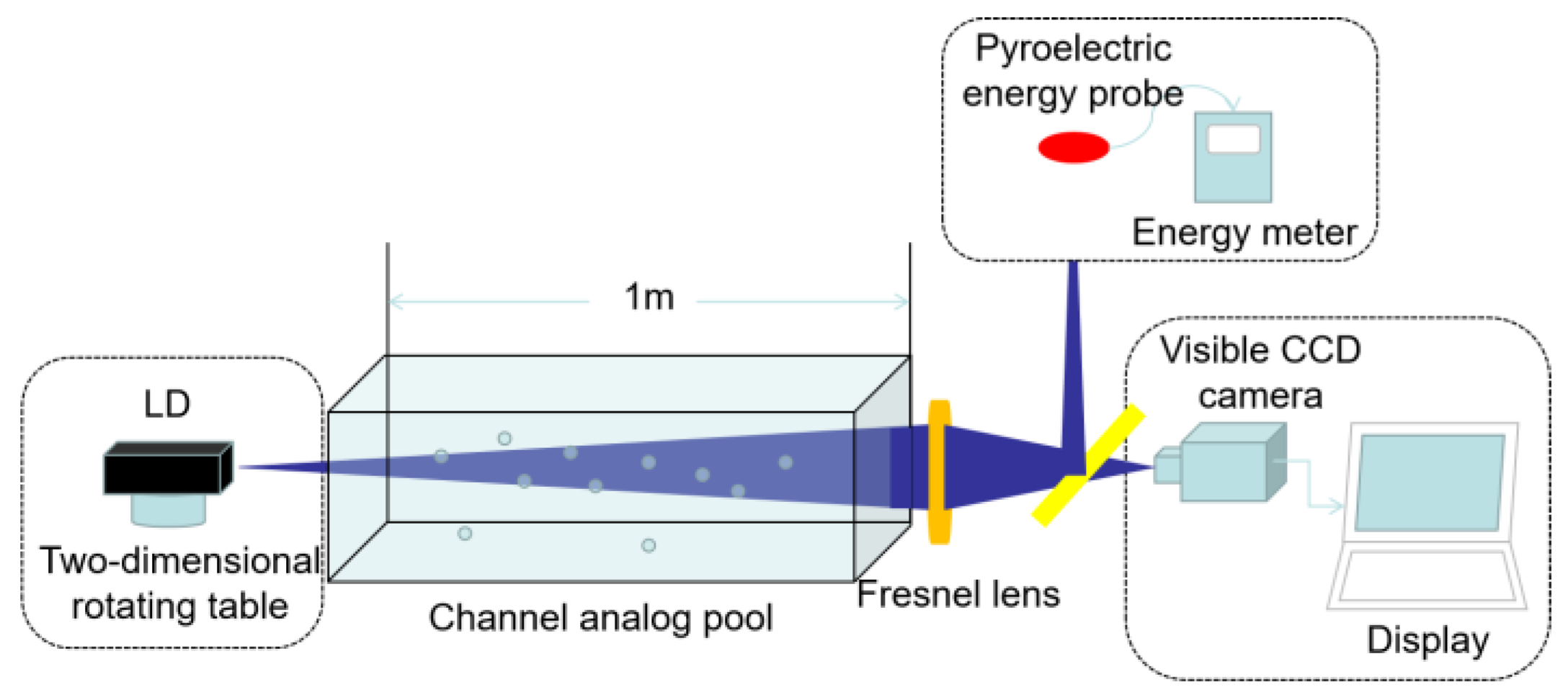
The optical transmitter is mainly composed of a signal source, a signal processing unit and an electro-optical conversion unit, as shown in Figure 2. Since the blue-green light bands (488 nm and 520 nm) are the optical Windows of the seawater channel, semiconductor lasers with wavelengths of 488 nm and 520 nm are selected as the test light sources [26]. The light source is installed on a two-dimensional turntable. By adjusting the turntable, the emission direction of the laser beam can be precisely controlled, and the emission power range is 0 to 50 mW. After passing through the signal processing and photoelectric conversion unit, the signal is transmitted in the channel in the form of light waves [27].
The optical signal passes through a 1-m-long underwater channel to reach the receiving end. After being focused by the Fresnel lens (Meiying Technology, Shenzhen, China, 80 mm diameter; 50 mm focal length), the laser spot is presented at the focal plane of the lens. The laser power was measured by a space optical power meter (Hioki, Kami, Japan, equipped with a 9742 probe, with a wavelength response range of 320–1100 nm and a maximum measurement power of 50 mW), and the focused spot was collected by a visible light charge-coupled device (CCD) camera (Hikvision, Hangzhou, China). Finally, the processed information is sent to the homestay, completing the underwater information transmission.
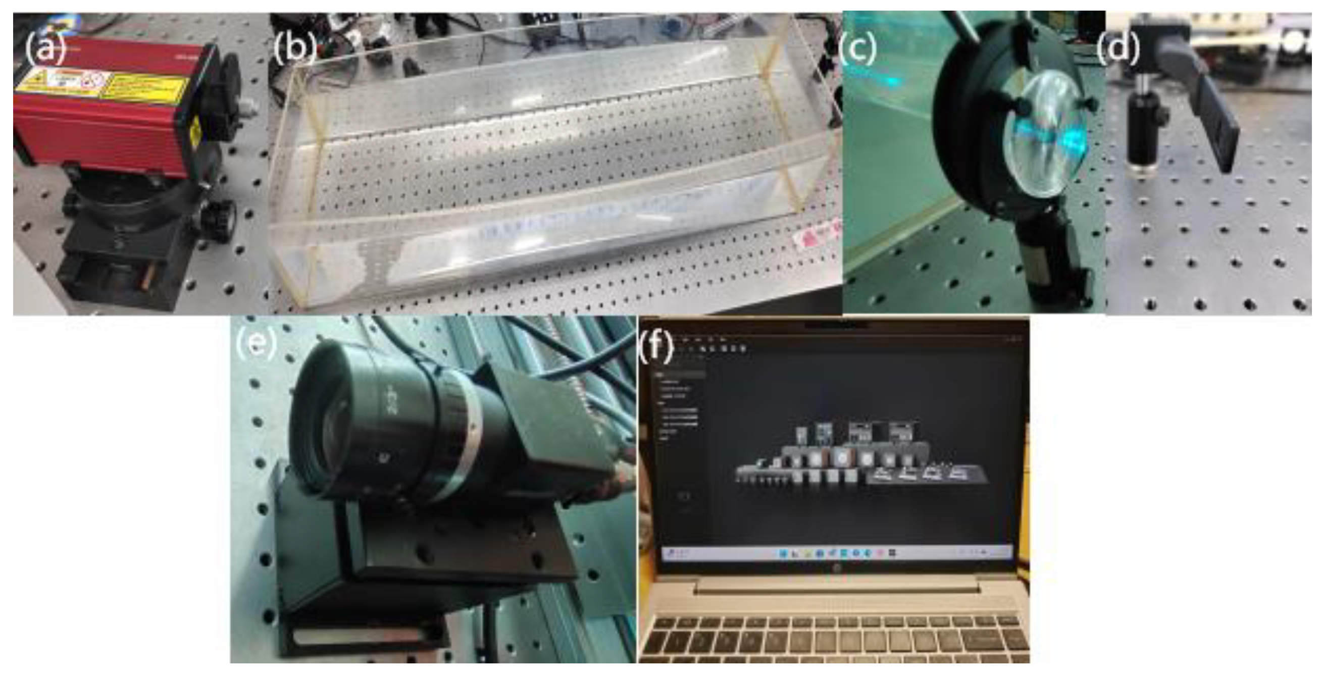
When building the experimental measurement system for the concentrating performance of the Fresnel lens, according to the actual measurement requirements and experimental conditions, the optical path between each optical device should be shortened as much as possible to reduce the loss of the laser beam during spatial transmission. Since the experiment was conducted over a short distance in the laboratory, the transmission loss of laser power in the atmospheric space can be ignored. By adjusting the optical path of the experimental system to ensure that all optical devices were on the same optical axis, an underwater wireless optical communication system based on a large-aperture and short-focal-length Fresnel lens was finally established, as shown in Figure 3 [28].

3. Results

Lasers with wavelengths of 488 nm and 520 nm were respectively incident on the smooth surface and sawtooth surface of the Fresnel lens. After the laser output stabilizes, position the target surface of the laser power meter probe at the focal plane of the Fresnel lens. Calibrate the detector position and ensure that the fixed lens focal plane is parallel to the detector surface. Use parallel blocks to verify this. By adjusting the one-dimensional rotary table, the angle between the Fresnel lens and the principal optical axis of the laser is controlled, that is, the incident angle of the laser beam is changed. Within the range of −2° to 2°, the optical power value received by the laser power meter is measured point by point at intervals of 1°.
The serrated surface of a Fresnel lens consists of a series of concentric, ring-shaped serrations, or step-like structures. The inclination angle of each serration is precisely calculated to effectively “fold” the continuous, curved surface of a traditional convex lens into the discrete serrations of a Fresnel lens. This design allows the inclined surface of each serration to refract incident light to the same focal point. The sawtooth structure reduces reflection losses by concentrating refraction; smooth surfaces, on the other hand, lose part of their light energy due to surface reflection (e.g., Fresnel reflection). Therefore, it can be concluded that the light-gathering efficiency of a Fresnel lens’s sawtooth surface differs from that of a smooth surface. Based on the experimental measurement data, the concentrating efficiency curves of 488 nm and 520 nm lasers when they were incident on the smooth surface and sawtooth surface of the Fresnel lens respectively within the incident angle range of −2° to 2° were calculated and plotted. Figure 4a and 4b respectively show the concentrating efficiency of the Fresnel lens when the laser incident surface is a smooth surface and a sawtooth surface. Figure 4c illustrates the light collection efficiency when 488-nm and 520-nm lasers are incident on an ordinary (plano-convex) lens at the same angle. The lens has an aperture of 80 mm and a focal length of 170 mm.
Due to the multi-regime scattering of the light beam after passing through the underwater channel, the spot of light reaching the Fresnel lens surface will deviate from the center of the lens. This deviation manifests the collective impact of the scattering regimes’ events on the directionality of the received photons after propagating in a water channel. Therefore, the light energy received when the light beam is incident perpendicularly is not the maximum value. As shown in Figure 4a, when a 520 nm laser is incident perpendicularly from the sawtooth surface of the Fresnel lens (with an incident angle of 0°), the concentrating efficiency is 47.17%. When the incident angle is −1°, the concentrating efficiency reaches the maximum value of 49.38%. The optical transmittance drops at −2° for the serrated lens (Figure 4a) and ordinary lens (Figure 4c). As shown in Figure 4b, when a 520 nm laser is incident perpendicularly from the smooth surface of the Fresnel lens (with an incident angle of 0°), the concentrating efficiency is 43.06%. When the incident angle is −1°, the concentrating efficiency reaches the maximum value of 46.51%. As shown in Figure 4c, when a 520 nm laser beam is incident perpendicularly (0° incidence angle) on the conventional lens, the concentration efficiency is 50.13%. When the incidence angle is −1°, the concentration efficiency reaches its maximum value of 51.22%. Comparison shows that the maximum concentration efficiency achieved with the conventional lens is higher than that with the Fresnel lens. This is because while the slanted surfaces of the Fresnel lens grooves are effective optical surfaces, the vertical surfaces of the grooves do not contribute to light concentration, leading to some optical loss. Additionally, the Fresnel lens exhibits slightly higher surface diffraction and scattering losses. However, leveraging its large aperture and short focal length characteristics, the Fresnel lens not only enhances the system’s reception field of view, thereby collecting more photons and resulting in an overall system concentration efficiency significantly higher than that of the conventional lens, but also enables a compact and lightweight optimized design for underwater wireless optical communication systems due to its very thin profile and minimal weight.
When the 488 nm laser was used as the test light source, the experimental results were basically consistent with the variation trend of the concentrating efficiency of the 520 nm laser, but the overall concentrating efficiency was lower than that of the 520 nm laser.
The experimental results indicate that the total concentration efficiency of the system using a Fresnel lens is higher than that with a conventional lens. Employing the installation method where light is incident on the sawtooth surface of the Fresnel lens improves concentration efficiency by 1% to 5% compared to incidence on the smooth surface. As the angle of incidence increases, the concentration efficiency of the Fresnel lens gradually decreases. Furthermore, while the trend of efficiency change is similar for both 488 nm and 520 nm lasers, the concentration efficiency of the former is generally lower than that of the latter.
Using a laser with a wavelength of 520 nm within the incident angle range of −2° to 2°, the underwater wireless optical communication system tests were conducted respectively on the tap water channel with an attenuation coefficient of −0.36307 m−1 and the clear lake channel with an attenuation coefficient of −0.9301 m−1. The results are shown in Figure 5. In the tap water channel, when the incident angle is −1°, the concentrating efficiency of the Fresnel lens reaches the maximum value of 46.51%. As the incident angle increases, the concentrating efficiency gradually decreases. In the clear lake channel, the variation trend of the concentrating efficiency is similar to that of the tap water channel. However, due to the large attenuation coefficient of lake water, the concentrating efficiency is reduced by approximately 10% to 40% compared to the tap water channel.
The focused spots produced by the 488 nm and 520 nm lasers passing through the Fresnel lens within the incident angle range of −2° to 2° were observed. The results are shown in Figure 6 and Figure 7. When the 488 nm laser passes through the tap water channel with an attenuation coefficient of −0.36307 m−1, due to the refraction of the light, the optical path is deflected, causing the focused spot to deviate from the center of the Fresnel lens. Meanwhile, as the incident angle changes, the position and size of the focused spot on the lens will also change accordingly. In an air-channel system, the maximum energy is received when the laser is incident perpendicularly on the surface of the condenser mirror. As the angle at which the light deviates from the optical axis of the condenser increases, the focused spot gradually deviates from the center of the lens, and the received energy also decreases accordingly.
Based on the above experimental measurement results, the optical distortion of the focused spots produced by 488 nm and 520 nm lasers passing through the Fresnel lens was further studied. The focused light spot generated by the 488 nm laser within the incident angle range of −2° to 2° was captured by a visible light CCD camera, and the results are shown in Figure 6. It can be seen from Figure 7a that when the 488 nm laser is incident on the Fresnel lens at 1°, the size of the focused spot is significantly larger than that when it is incident at 0°, and the spot power distribution is relatively uniform. However, when the incident angle increases to 2°, the size of the focused spot decreases and a certain degree of optical distortion occurs. The spot power distribution is no longer uniform: strong power points appear in the positive X direction of the optical axis, while the spot power in the negative X direction of the optical axis is slightly lower than that in the positive direction.
Therefore, when studying the optical path characteristics and the changes of the focused light spot of the underwater wireless optical communication system, the influence of the refraction effect of the underwater channel on the optical path needs to be fully considered.
It can be seen from Figure 7a that when the incident angle of the 520 nm laser is −1°, the focused spot presents a regular geometric circular shape. The power density of the central spot is the largest, and the power distribution of the first ring gradually weakens, but its optical power is higher than that of the first ring of the focused spot of the 488 nm laser in Figure 6a. This phenomenon indirectly indicates that the concentrating efficiency of the Fresnel lens on the 520 nm laser is higher than that on the 488 nm laser. As the incident angle of the 520 nm laser increases, as shown in Figure 7b–d, coma aberration begins to occur in the focused spot. In addition, due to the turbulence of water and the temperature gradient, which may cause phase distortion of the beam, the wavefront distortion is relatively severe.
The experimental results show that the constraint conditions for coma distortion of the focused spot of the 520 nm laser are more lenient than those of the 488 nm laser, indicating that using the 520 nm laser signal light source allows the deployment of a larger FOV angle on the receiver side. For a single lens, the longer the wavelength of the incident light beam, the longer its focal length. However, due to the scattering effect of water, the light beam may diverge, increasing the received optical spot size and decreasing its uniformity.

4. Discussion

Chromatic aberration occurs when the laser is incident on the Fresnel condenser. Therefore, the focus of subsequent research will be to deeply explore the problem of spot non-uniformity caused by dispersion. This research is of great significance for improving the underwater wireless optical communication system based on Fresnel lenses.

5. Conclusions

Compared with traditional lenses, Fresnel lenses have the advantages of strong converging ability, small volume and light weight. In the application of Fresnel lenses in the UWOC system, characteristic parameters such as concentrating efficiency and uniformity of the focused light spot need to be considered. These parameters directly affect the communication performance of the underwater wireless optical communication system. Through the analysis of the experimental results, the article obtained the optimal focusing performance of the Fresnel lens and improved the focusing performance of the Fresnel lens in the UWOC system, providing a valuable option for the long-distance transmission research of the UWOC system.

Author Contributions

Validation, S.H.; Formal analysis, Z.Z.; Investigation, X.Z.; Writing—original draft, Y.Z.; Writing—review & editing, P.Z. All authors have read and agreed to the published version of the manuscript.

Funding

This research was funded by the National Natural Science Foundation of China (NSFC) Regional Joint Fund Key Support Project (Grant No. U22A2008), the Natural Science Foundation of Jilin Province (Grant No. YDZJ202301ZYTS394), and the Development Fund of the Key Laboratory of Underwater Acoustic Countermeasure Technology (Grant No. CX-2022-032). And The APC was funded by the National Natural Science Foundation of China, the Department of Science and Technology of Jilin Province, and the Key Laboratory of Underwater Acoustic Countermeasure Technology.

Institutional Review Board Statement

Not applicable.

Informed Consent Statement

Not applicable.

Data Availability Statement

Data are contained within the article.

Conflicts of Interest

The authors declare no conflict of interest.

References

  1. Zhou, H.; Zhang, M.; Wang, X.; Ren, X. Design and Implementation of More Than 50m Real-Time Underwater Wireless Optical Communication System. J. Light. Technol. 2022, 40, 3654–3668. [Google Scholar] [CrossRef]
  2. Omar, N.M.S.; Salah, A.A.; Ammar, H.M. Underwater optical wireless communication system performance improvement using convolutional neural networks. AIP Adv. 2023, 13, 045302. [Google Scholar] [CrossRef]
  3. Ge, W.; Song, G.; Qin, S.; Zhang, Y.; Du, Z.; Xu, J. Weak signal detection based on pulse width counting method for underwater wireless optical communication with an analog mode PMT detector. Opt. Express 2024, 32, 23404–23415. [Google Scholar] [CrossRef]
  4. Li, D.C.; Chen, C.C.; Liaw, S.K.; Afifah, S.; Sung, J.Y.; Yeh, C.H. Performance Evaluation of Underwater Wireless Optical Communication System by Varying the Environmental Parameters. Photonics 2021, 8, 74. [Google Scholar] [CrossRef]
  5. Cai, R.; Zhang, M.; Dai, D.; Shi, Y.; Gao, S. Analysis of the Underwater Wireless Optical Communication Channel Based on a Comprehensive Multiparameter Model. Appl. Sci. 2021, 11, 6051. [Google Scholar] [CrossRef]
  6. Liu, A.; Zhang, R.; Lin, B.; Yin, H. Multi-Degree-of-Freedom for Underwater Optical Wireless Communication with Improved Transmission Performance. J. Mar. Sci. Eng. 2023, 11, 48. [Google Scholar] [CrossRef]
  7. Zayed, M.M.; Shokair, M.; Elagooz, S.; Elshenawy, H. Feasibility analysis of line of sight (LOS) underwater wireless optical communications (UWOCs) via link budget. Opt. Quant Electron 2024, 56, 1012. [Google Scholar] [CrossRef]
  8. Simpson, J.A.; Hughes, B.L.; Muth, J.F. Smart Transmitters and Receivers for Underwater Free-Space Optical Communication. Sel. Areas Commun 2012, 30, 964–974. [Google Scholar] [CrossRef]
  9. Oubei, H.M.; Duran, J.R.; Janjua, B.H.; Wang, Y.; Tsai, C.T.; Chi, Y.C.; Ng, T.K.; Kuo, H.C.; He, J.H.; Alouini, M.S.; et al. 4.8 Gbit/s 16-QAM-OFDM transmission based on compact 450-nm laser for underwater wireless optical communication. Opt. Express 2015, 23, 23302–23309. [Google Scholar] [CrossRef] [PubMed]
  10. Chen, Y.F.; Kong, M.W.; Ali, T.; Wang, J.J.; Sarwar, R.; Han, J.; Guo, C.Y.; Sun, B.; Deng, N. 26 m/5.5 Gbps air-water optical wireless communication based on an OFDM-modulated 520-nm laser diode. Opt. Express 2017, 25, 14760–14765. [Google Scholar] [PubMed]
  11. Wang, D.; Lan, T. Design of a gradient-index lens with a compound parabolic concentrator shape as a visible light communication receiving antenna. Appl. Opt. 2018, 57, 1510–1517. [Google Scholar] [CrossRef]
  12. Hu, S.Q.; Mi, L.; Zhou, T.H.; Chen, W.B. 35.88 attenuation lengths and 3.32 bits/photon underwater optical wireless communication based on photon-counting receiver with 256-PPM. Opt. Express 2018, 26, 21685–21699. [Google Scholar] [CrossRef]
  13. Sabbagh, A.G. Long-range underwater optical wireless communication systems in turbulent conditions. Opt. Express 2023, 31, 21311–21329. [Google Scholar] [CrossRef]
  14. Qi, Z.; Wang, L.; Liu, P.; Bai, M.; Yu, G.; Wang, Y. Full-duplex underwater wireless blue light communication. Opt. Express 2023, 31, 9330–9338. [Google Scholar] [CrossRef] [PubMed]
  15. Han, S.; Yue, P.; Yi, X. Study of an underwater accurate channel model considering comprehensive misalignment errors. J. Opt. Soc. Am. 2022, 39, 1014–1024. [Google Scholar] [CrossRef]
  16. Ke, X.; Yang, S.J.; Sun, Y.; Liang, J.Y.; Pan, X.Y. Underwater blue-green LED communication using a double-layered, curved compound-eye optical system. Opt. Express 2022, 30, 18599–18616. [Google Scholar]
  17. Manimegalai, C.T.; Bhatta, H.; Thakur, H.; Iliyas, A. Channel modeling for UWOC: A simulation approach. J. Opt. 2022, 51, 810–818. [Google Scholar] [CrossRef]
  18. Fei, C.; Wang, Y.; Du, J.; Chen, R.L.; Lv, N.F.; Zhang, G.W. 100-m/3-Gbps underwater wireless optical transmission using a wideband photomultiplier tube (PMT). Opt. Express 2022, 30, 2326–2337. [Google Scholar] [CrossRef] [PubMed]
  19. Zhao, M.; Miyamoto, T. Optimization for Compact and High Output LED-Based Optical Wireless Power Transmission System. Photonics 2022, 9, 14. [Google Scholar] [CrossRef]
  20. Wang, M.; Yu, J.; Zhao, X.; Bian, C.; Zhou, W.; Wang, K. K-Means Non-Uniform-Quantization Digital–Analog Radio-over-Fiber Scheme for THz-Band Photonics-Aided Wireless Fronthaul. Opt. Lett. 2024, 49, 2801–2804. [Google Scholar]
  21. Lu, W.W.; Chen, S.Y.; Xiong, Y.P.; Liu, J.F. A single ball lens-based hybrid biomimetic fish eye/compound eye imaging system. Opt. Commun. 2021, 480, 126458. [Google Scholar] [CrossRef]
  22. Kumar, V.; Shrivastava, R.; Untawale, S. Fresnel Lens: A Promising Alternative of Reflectors in Concentrated Solar Power. Renew. Sustain. Energy Rev. 2015, 44, 376–390. [Google Scholar] [CrossRef]
  23. Tan, N.Y.J.; Zhang, X.; Neo, D.W.K.; Huang, R.; Liu, K.; Kumar, A.S. A Review of Recent Advances in Fabrication of Optical Fresnel Lenses. J. Manuf. Process. 2021, 71, 113–133. [Google Scholar] [CrossRef]
  24. Dhanumalayan, E.; Joshi, G.M. Performance Properties and Applications of Polytetrafluoroethylene (PTFE)—A Review. Adv. Compos. Hybrid Mater. 2018, 1, 247–268. [Google Scholar] [CrossRef]
  25. Price, D.M.; Jarratt, M. Thermal Conductivity of PTFE and PTFE Composites. Thermochim. Acta 2002, 392, 231–236. [Google Scholar] [CrossRef]
  26. Yeh, N.; Yeh, P. Analysis of Point-Focused, Non-Imaging Fresnel Lenses’ Concentration Profile and Manufacture Parameters. Renew. Energy 2016, 85, 514–523. [Google Scholar] [CrossRef]
  27. Shaw, J.A. Radiometry and the Friis Transmission Equation. Am. J. Phys. 2013, 81, 33–37. [Google Scholar] [CrossRef]
  28. Nagatsuma, T.; Horiguchi, S.; Minamikata, Y.; Yoshimizu, Y.; Hisatake, S.; Kuwano, S.; Yoshimoto, N.; Terada, J.; Takahashi, H. Terahertz Wireless Communications Based on Photonics Technologies. Opt. Express 2013, 21, 23736–23747. [Google Scholar] [CrossRef] [PubMed]
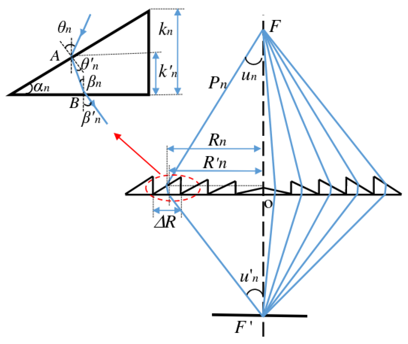
Figure 1. The concentrating principle diagram of the Fresnel lens.
Photonics 12 01010 g001
Figure 2. Model diagram of underwater wireless optical communication system based on Fresnel lens.
Photonics 12 01010 g002
Figure 3. Underwater wireless optical communication system based on Fresnel lens (a) LD; (b) Underwater channel; (c) Fresnel lens; (d) Thermoelectric probe; (e) Visible light CCD camera; (f) Monitor.
Photonics 12 01010 g003
Figure 4. The focusing efficiency of 488 nm and 520 nm lasers passing through different surfaces of a Fresnel lens and a regular lens at incident angles of −2°~2°. (a) Serrated surface; (b) Smooth surface; (c) Ordinary lens.
Photonics 12 01010 g004
Figure 5. The focusing efficiency of a 520 nm laser passing through a Fresnel lens at an incident angle of −2°~2° under two water quality conditions: tap water and lake water.
Photonics 12 01010 g005
Figure 6. The focused spot generated by a 488 nm laser passing through a Fresnel lens at an incident angle of −2° to 2°. (a) −2°; (b) −1°; (c) 0°; (d) 1°; (e) 2°.
Photonics 12 01010 g006
Figure 7. The focused spot generated by a 520 nm laser passing through a Fresnel lens at an incident angle of −2° to 2 °. (a) −2°; (b) −1°; (c) 0°; (d) 1°; (e) 2°.
Photonics 12 01010 g007
Disclaimer/Publisher’s Note: The statements, opinions and data contained in all publications are solely those of the individual author(s) and contributor(s) and not of MDPI and/or the editor(s). MDPI and/or the editor(s) disclaim responsibility for any injury to people or property resulting from any ideas, methods, instructions or products referred to in the content.