Article

A Hybrid Design for Frequency-Independent Extreme Birefringence Combining Metamaterials with the Form Birefringence Concept

by
Can Koral
1,*,† and
Fulya Bagci
2,*,†
1
Department of Health Sciences, University of Basilicata, Viale dell’Ateneo Lucano 10, 85100 Potenza, Italy
2
Department of Physics Engineering, Faculty of Engineering, Ankara University, Besevler, 06100 Ankara, Turkey
*
Authors to whom correspondence should be addressed.
These authors contributed equally to this work.
Photonics 2024, 11(9), 860; https://doi.org/10.3390/photonics11090860
Submission received: 25 July 2024 / Revised: 3 September 2024 / Accepted: 10 September 2024 / Published: 12 September 2024
(This article belongs to the Special Issue Emerging Trends in Metamaterials and Metasurfaces Research)

Abstract

:
With advances in terahertz technology, achieving high and nearly constant birefringence over a wide frequency range plays an extreme role in many advanced applications. In the past decade, significant research efforts have been devoted to creating new systems or elements with high birefringence. To our knowledge, the maximum birefringence attainable using artificial crystals, intrinsic liquid crystals or fiber-based systems has been less than unity. More importantly, the birefringence created in previous studies has exhibited a strong frequency dependence, limiting their practical applications. In this work, we propose a novel approach to achieve extraordinarily high birefringence over a broad terahertz frequency band (>100 GHz). To address the limitation of frequency dependence, we combined the principle of metamaterials with the form birefringence concept. First, we designed a metamaterial with an exceptionally high refractive index, thoroughly characterizing it using simulations and analytical analysis. Next, we systematically investigated the form birefringence concept, exploring its frequency response, geometric limitations, and complex refractive index differences between constituent elements. Finally, we designed a hybrid material system, combining the strengths of both metamaterials and form birefringence. Our results demonstrate the feasibility of achieving a birefringent medium exceeding three orders of magnitude higher than previous reports while maintaining a time-invariant frequency response in the sub-terahertz regime.

1. Introduction

The terahertz and sub-terahertz region of the electromagnetic spectrum offers tremendous potential for advanced scientific and technological applications [1,2]. This frequency band presents unique chances to investigate and regulate a wide range of complex phenomena, from molecular-scale fundamental processes to the phase changes observed in diverse solid materials and biological systems [3,4,5]. The capacity to precisely control THz waves unlocks exciting possibilities across numerous fields, such as spectroscopy, imaging, communications, and the study of nonlinear effects in advanced materials. Apart from using THz waves as a spectroscopic tool, the sensitive control over polarization states in novel devices, such as metamaterials and field–field interactions in condensed matter systems, is an emerging field of research [6]. Precise control and manipulation of electromagnetic wave polarization is crucial across a diverse range of scientific and industrial applications, including quantum information processing, ultrafast photonics, and advanced imaging techniques [7]. Recent advances have shown the potential of using tailored THz beams to achieve a higher degree of control over matter and intense field transients [8]. In this context, beam shaping and controlled manipulation of amplitude, phase, polarization, and spatial degrees of freedom, including orbital angular momentum, play a key role in optics and photonics [9]. These advancements have led to applications in polarization-sensitive spectroscopy, advanced imaging, laser technologies, optical sensing, and high-speed communications [10,11,12,13,14,15,16,17].
Even today, the available structures in the THz regime are still limited and many of the successful demonstrations have been accomplished mainly in the optical regime by using liquid crystals or intrinsically birefringent crystals [18,19]. In these systems, beam front manipulation is realized by using axially symmetric wave plates as the main building blocks. Liquid crystal-based systems may not be suitable for high-field terahertz applications due to the temperature-dependent nature of their anisotropic response. Additionally, at terahertz frequencies, these commonly used methods are difficult to implement due to the high extinction coefficient and/or the inherent limitations of the materials, such as the wavelengths being much larger than the birefringent media structures.
While advanced polarization control techniques have been demonstrated in the optical domain, their applicability in the terahertz regime is limited. The parameter Δn, which denotes the difference in refractive indices between the two orthogonal polarizations of light traveling through the birefringent material, characterizes the degree of birefringence [20]. Unfortunately, the achievable birefringence with these approaches has been limited to values less than Δn < 1 in the THz range [21]. Additionally, these approaches encounter challenges due to the high absorption and intrinsic limitations of the materials at terahertz frequencies. Furthermore, liquid crystal-based systems exhibit wavelength-dependent responses, high costs, and are sensitive to temperature variations [22,23]. Addressing these challenges, advanced plasmonic structures present a potential solution. Recent studies have shown the possibility of actively manipulating polarization states of light using graphene-based hybrid plasmonic waveguide structures [24,25]. It is important to note that, application-wise, these studies are far from achieving practical device commercialization.
In this paper, we propose a hybrid approach that combines the advantages of metamaterials and form birefringence to achieve an exceptionally high birefringence over a broad spectral range in the terahertz regime. The first key design element of the proposed system is to use periodically structured dielectric interfaces to create high-birefringence media. This approach, known as “form birefringence”, has been applied to a variety of devices such as wave plates, filters, Bragg reflectors, and phase shifters [26,27,28]. Form birefringence refers to the birefringence that arises from the anisotropy in the geometric structure of the medium, rather than the intrinsic anisotropy of the constituent materials. This concept can also be correlated with the concept of superlattices [29,30], which involve stacking layers of materials with different optical properties to create a periodic structure that can manipulate light in a controlled manner. This provides a promising approach for developing terahertz components with tailored polarization properties. Even if the achievable birefringence is limited with the highest index of refraction contrast of the constituent elements used, it makes it possible to achieve birefringence levels Δn > 1, which offers superior applicability compared to the birefringence achievable using existing conventional methods, utilizing artificial crystals, liquid crystals, or fiber-based systems where the achievable birefringence is limited to Δn < 1.
While conductive materials can also be used as the building block to enhance the refractive index contrast, the form birefringence method also allows for the use of relatively transparent materials like common dielectrics to create relatively high birefringence. This becomes a key point since the refractive indices of dielectric materials are not as high as metals, still, their geometric anisotropy can be used to create highly birefringent media without the losses associated with metals [27,31,32].
The second key element of our study is the use of metamaterial technology [33,34,35], which has enabled the development of novel materials with tailored electromagnetic properties, that were previously unattainable with conventional dielectric and/or metallic materials. By carefully designing the geometry and arrangement of the constituent elements, metamaterials can exhibit effective optical properties not found in nature, such as perfect absorption [36,37,38], negative refractive index [39,40], extremely high refractive index [41,42,43] or even near-zero index values [44,45]. This opens up new possibilities for controlling the propagation and polarization of electromagnetic waves, including in the terahertz frequency range.
We would like to underline that, generally, these extreme refractive indices achieved by using metamaterials are typically limited to around the resonance points of the designed devices, showing a strong frequency dependence, which constrains their practical utility for broadband applications. Recent advancements in metamaterial design and research have enabled the creation of materials with exceptionally high refractive indices, yet the exploration has primarily focused on their electrical response. To our knowledge, there has been little investigation into the anisotropic behavior of the designed metamaterial devices [46]. Additionally, the complex response characteristics of these metamaterials remain largely unexplored in the literature, especially concerning the anisotropic response attainable.
The main goal of this work is to not only achieve a high index contrast using metamaterials but also to explore and control the dispersion properties of the index contrast by combining it with the form birefringence concept. The proposed hybrid system design aims to provide extreme birefringence to enable advanced polarization control and manipulation capabilities. Moreover, the attainable high birefringence remains almost constant at Δn~14 at the sub-THz region in a bandwidth greater than 100 GHz.

2. Materials and Methods

2.1. Metamaterial Design and S-Parameter Results

I-shaped metamaterial structure inspired by [42] is considered as the structure of the metamaterial for its potential of high refractive index. The front and lateral schematic view of the unit cell of the metamaterial structure is shown in Figure 1a,b, respectively. Values of the geometrical parameters are given in the caption of Figure 1. The I-shaped thin metamaterial is made from gold with a conductivity of 4.56 × 10⁷ S/m and a thickness of 0.1 µm. The resonator is embedded inside the middle of the polyimide substrate material, which has a complex refractive index of n = 1.8 + 0.4j [47]. The gap between adjacent unit cells in y-direction is 1.2 µm and the length of the horizontal arms of the I-shaped metamaterial (w) is 58.8 µm. Therefore, a large amount of charge distribution can be accumulated at the edges of the arms of the I-shaped metamaterial, providing a large dipole moment that leads to a high refractive index. It can be anticipated that in order to have a high permittivity in the y-direction, the length of the vertical arm of the I-shaped metamaterial should be kept high and the gap width between adjacent unit cells should be considered small. Since the area subtended by the current loops of an I-shaped structure is small, the diamagnetic effect is weak, and a high refractive index can be obtained at resonance.
The electromagnetic response of the metamaterial is calculated by using a 3D full-wave electromagnetic solver, CST Studio Suite. Unit cell boundary conditions are assumed along the ±x and ±y directions and the structure is excited from 100 µm distance with a plane wave.

2.2. Refractive Index Retrieving Method from S-Parameters

It is well known that the metamaterial behaves as an effective homogenous medium to the incoming electromagnetic waves in the long wavelength limit [48,49]. Hence, their effective permittivity, permeability and refractive index can be determined from characterization of the scattering parameters of the homogenous slab that mimics the metamaterial. Commonly used extraction technique of effective parameters relies on the solution of the complex wave equations under sufficient number of boundary conditions [48,49,50].
Scattering parameters for a normal excitation of a plane wave on the metamaterial can be expressed by Equations (1) and (2) [47,50]:
S 11 = R 01 1 e i n k 0 d 1 R 01 2 e i n k 0 d
S 21 = ( 1 R 01 2 ) e i n k 0 d 1 R 01 2 e i n k 0 d
Here R01 is the half-space reflection coefficient, n is the effective refractive index and d is the thickness of the metamaterial slab. In addition, k0 is the wavenumber of incident wave in free space and i represents the imaginary unit. The impedance ( Z ) and the expression e i n k 0 d   can be extracted from Equations (1) and (2) as follows:
Z = 1 + S 11 2 S 21 2 1 S 11 2 S 21 2
n k 0 d = X ± i 1 X 2
The parameter, X , equals to ( 1 S 11 2 + S 21 2 ).
The effective refractive index is a complex parameter, and it is determined as follows [47,50]:
n = 1 k 0 d ln e i n k 0 d + 2 m π i   ln e i n k 0 d  
Here (•) and (•) indicate the real and imaginary part operators, respectively, and m is the branch number of the refractive index, which must be an integer number. The real part of Z and the imaginary part of n must satisfy the conditions for a passive medium, requiring both to be non-negative.

2.3. Calculation of Form Birefringence

A birefringent material can be constructed in the form of two alternating slabs with high and low refractive indices, denoted by n1 and n2, with the corresponding slab lengths (or widths), L1 and L2. The attainable “form birefringence” of a given system can be analytically determined by considering the effective quasi-static refractive index for the electric field aligned parallel and perpendicular to the alternating pattern orientation. This quasi-static approach is valid as long as the wavelength is larger than the dimension of the constituting layers. The provided equations given as Equation (1) in [51] allow a quick estimate of the magnitude of birefringence within the effective medium theory (EMT) framework. This framework is also often used to describe the optical properties of superlattices, which are treated as a homogeneous material with an effective refractive index that depends on the properties and arrangement of the constituent layers [52].
While these equations are widely used to design devices for tailoring the polarization states of light, they do not account for the anisotropic nature of the materials employed. Since the complex refractive indices of metamaterials can exhibit high anisotropic responses, the equations used for the calculation of quasi-static refractive indices for TE and TM polarizations (nTE,0 and nTM,0) can be rearranged in the forms of Equations (6) and (7) to include the transverse electric (TE) and transverse magnetic (TM) responses of the two slab materials:
n T E , 0 = f 1 n 1 , T E 2 + f 2 n 2 , T E 2    
n T M , 0 = 1 f 1 / n 1 , T M 2 + f 2 / n 2 , T M 2  
Here n 1 , T E , n 1 , T M and n 2 , T E , n 2 , T M are the refractive index of the high and low refractive index material under the TE and TM mode polarizations, respectively. f 1 and f 2 are the volumetric fractions of the high-index material and the low-index slab, respectively. The low-index slab is considered as air slab in this study.
As well studied in the literature, this assumption remains valid at wavelengths near the quasi-static limit and loses its validity as scattering and waveguiding effects become dominant at higher frequencies [27,53]. A more sophisticated approach offers second-order effective medium theory solutions. The second-order effective optical parameters are defined as:
n T E = n T E , 0 2 + 1 3 Λ λ π f 1 f 2 1 n 1 , T E 2 2 1 / 2
n T M = n T M , 0 2 + 1 3 Λ λ π f 1 f 2 1 1 n 1 , T M 2 n T E , 0 n T M , 0 3 2 1 / 2
where Λ = L M M + L a i r is the period given by the whole structure (LMM is the length of the metamaterial (MM) layer). The volume fractions of the structures are given by f M M = L 1 L 1 + L 2 and f a i r = 1 f M M .
The provided equations (Equations (8) and (9)) reveal that the periodic structures induce positive dispersion even for non-dispersive materials. This assumption remains valid at wavelengths near the quasi-static limit, as indicated by the Λ λ relation. However, when the periodicity surpasses the incident wavelength, scattering and waveguiding effects become dominant, restricting the device’s operational bandwidth.

3. Results and Discussion

3.1. S-Parameter Results

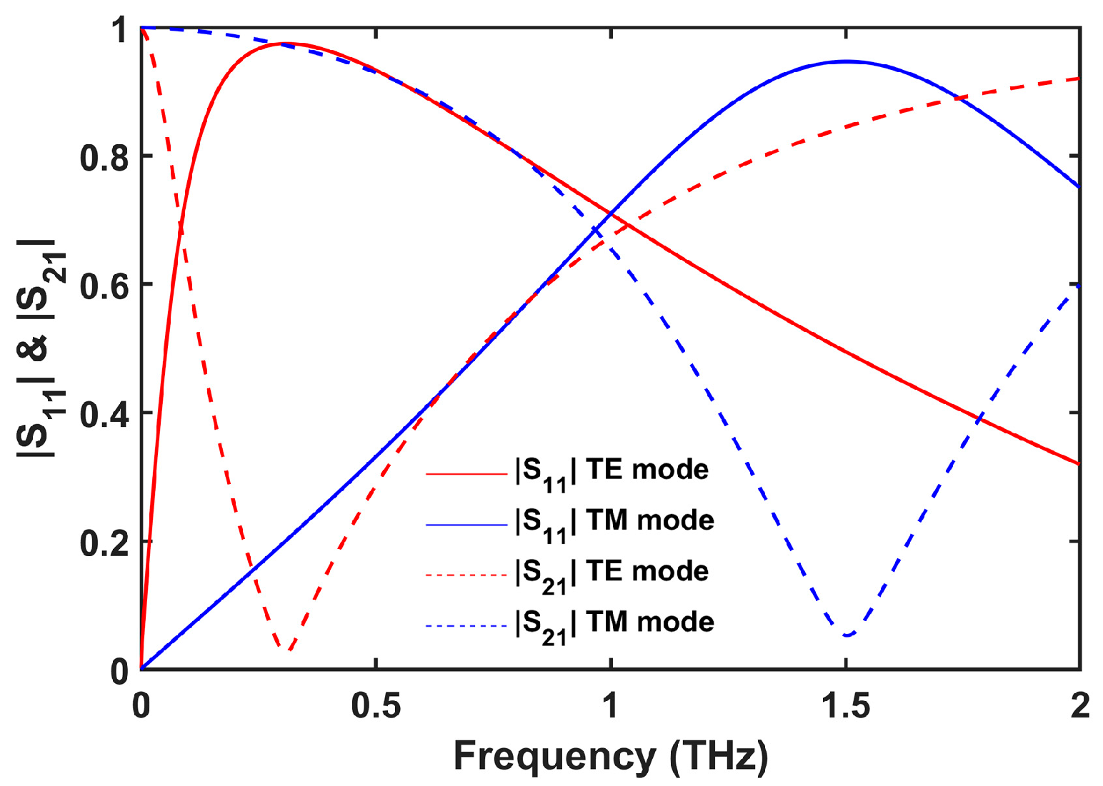
The reflection and transmission spectra of the proposed metamaterial for normally incident THz waves are illustrated in Figure 2. A transmission dip at 0.3 THz appears when the metamaterial is excited by a plane wave polarized through the y-direction (TE mode). The resonance shifts to 1.5 THz when the polarization of the impinging wave rotates 90° (TM mode). This is expected since the capacitive and inductive effects are weaker along the x-direction. Hence, for normally incident waves, around the TE mode resonance, we expect a higher effective refractive index than that for the TM mode, creating an anisotropy. The full-width at half-maximum bandwidths of transmission response for the TE and TM modes are calculated to be 0.62 and 0.75 THz, respectively.

3.2. Effective Refractive Index Properties of the Metamaterial

The effective refractive indices of the metamaterial under normally incident TE and TM mode excitations are calculated based on the S-parameter results following Equation (5). The calculated complex refractive indices are plotted in Figure 3a,b, for TE and TM mode excitations, respectively. The extracted refractive index for TE mode excitation reaches 60.5 at 0.3 THz frequency. A significant enhancement in the effective refractive index is obtained by the strong capacitive effect between the neighboring unit cells and the weak diamagnetic effect due to the thin metallic wire. On the other hand, the effective refractive index is around 5 at the quasi-static limit for the TM mode excitation and slowly increases as frequency increases. A figure-of-merit (FOM), defined as Re(n)/Im(n), is used to characterize the amount of loss of the designed metamaterial [40,47]. The FOM value is obtained to be above 10 at frequencies between 0.10 and 0.25 THz, for both parallel and perpendicular excitations. This points to the low loss feature of the metamaterial at these frequencies.

3.3. Form Birefringence in Highly Anisotropic Media

While the form birefringence concept has been extensively studied in the context of relatively low-index contrast and isotropic materials, the frequency response and resulting birefringence achievable using high-index metamaterials in the presence of extreme anisotropy were largely unexplored in the literature.
In this section, we aimed to demonstrate the limits and differences between the static case and second-order EMT solutions when using extremely high-index contrast materials. This allowed us to estimate the appropriate volume fraction of the extremely anisotropic metamaterial in the hybrid alternating metamaterial-air grooves system to achieve a high and time-invariant birefringence response.
We investigated the birefringence properties for two distinct scenarios—one for an isotropic system and another for an anisotropic system. For this reason, we employed both static state and second-order electromagnetic solutions introduced by Equations (6)–(9), respectively, and compared the analytical results. It should be kept in mind that, since the second-order electromagnetic solutions incorporate the solutions obtained from the static case [51], it is important to understand the relationship between the validity of the estimation and the periodicity of the structure at the chosen frequency band of operation.
The static solutions do not include the exact values of the periodicity of the elements but only their volume fractions. In contrast, the chosen length of periodicity directly influences the solutions of the second-order calculations. We have calculated the static solution for volume fractions of the hypothetically high index material (HIM) with respect to the hybrid system, ( f H I M = L 1 L 1 + L 2 ), ranging from 0.5 to 1. This high-index material represents a metamaterial in our final hybrid design in the form birefringence concept with air grooves. Later, we introduced these results into the second-order equations for a fixed periodicity ( Λ = L H I M + L a i r ) and a fixed frequency of choice. The effective optical material parameters are calculated for a fixed periodicity of 250 µm and the frequency of choice at 0.16 THz. The frequency chosen is the one where the imaginary part of the calculated refractive index (extinction coefficient) is close to zero, as shown in the calculated frequency response of the designed metamaterial in Figure 3, in order to achieve the lowest absorption. As can be seen in Figure 3, the designed metamaterial is characterized to give a refractive index response as nTE ≈ 25 and nTM ≈ 5 at 0.16 THz. To this concern, we have systematically increased the refractive index, starting from a moderate value of n = 2.5, which is achievable using naturally occurring materials. We then gradually raised it up to extreme refractive index values, to be specific, up to n = 25.
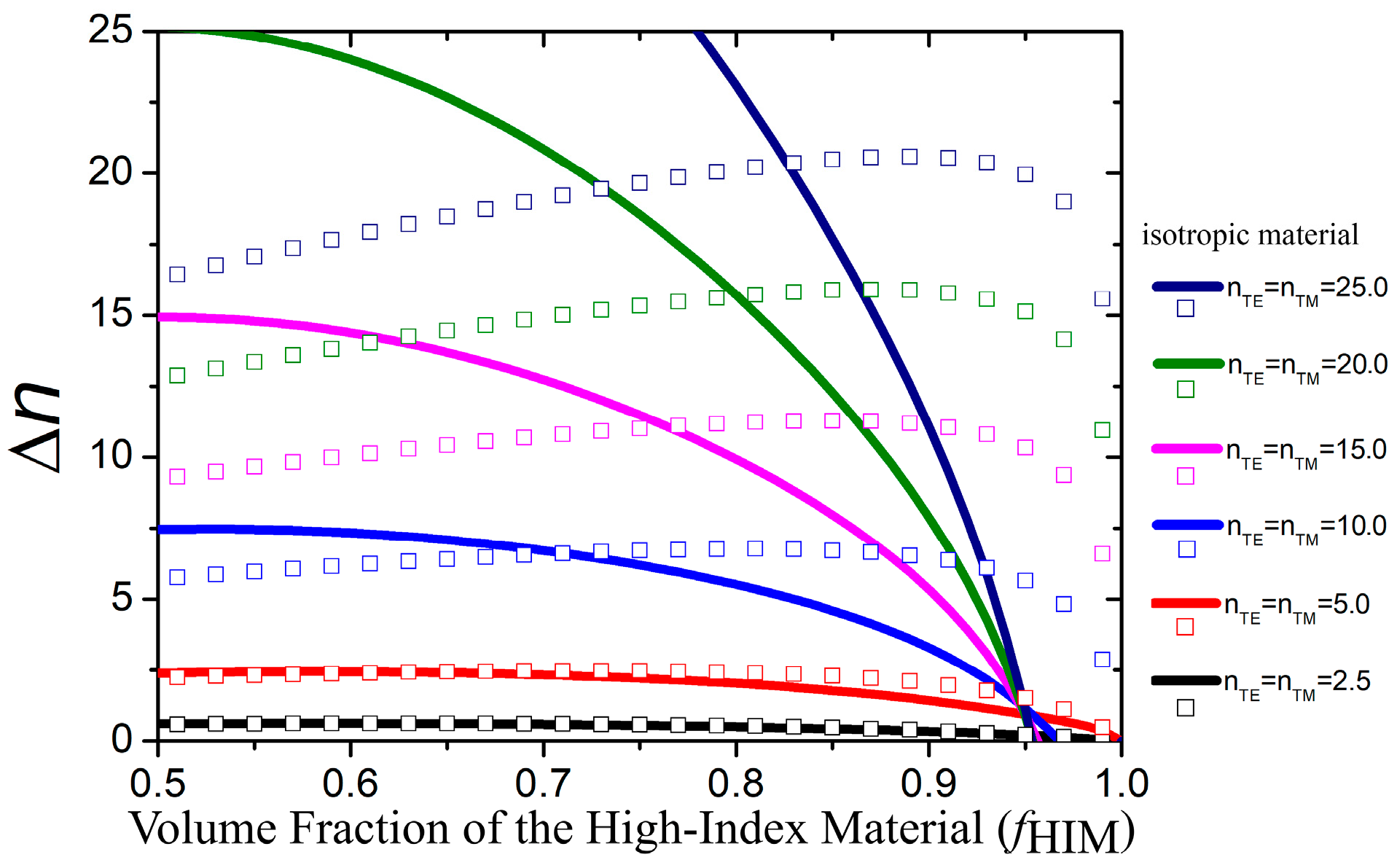
To better understand the birefringence for the two alternating high index material/air systems in the form birefringence arrangement [51], first, we dealt with the case when the material is isotropic. We note here that the electric field vector is parallel to the air grooves for the TE mode excitation whereas it is perpendicular for the TM mode (see Figure 8). A plot of the static and the 2nd order form birefringence solutions with respect to the volume fraction of the isotropic material is illustrated in Figure 4, for various effective refractive indices of the material, ranging between 2.5 and 25.0. It can be easily observed from this plot that for low effective refractive indices the 2nd order solutions show almost the same responses in comparison with the static response. As the magnitudes of the refractive indices increase, the degree of deviation between quasi-static and 2nd order solutions also increases. It is also evident from Figure 4 that birefringence decreases as the volume fraction of the high-index material increases and this decrease becomes sharper for the higher-index material.
The anisotropic material schemes under the influence of form birefringence for the chosen fixed volume ratio and frequency are also investigated in two categories. In the first/second category, the effective refractive index of the material under TM/TE mode excitation is kept constant to have a relatively low value, 5, or a high value, 25. Figure 5a shows the change in birefringence as a function of the volume fraction ratio of the high index material for different nTE values between 2.5 and 25 when nTM = 25. The most important observation from the given analysis is that for the anisotropic case when the nTM values are fixed to the maximum used in the isotropic analysis (25 in this case) and the nTE values are substantially increased, the contribution of the anisotropy does not result in a significant difference compared to the isotropic solutions as can be observed from the similarity between Figure 4 and Figure 5a. In contrast, when the nTE values are fixed to the maximum from the isotropic case and the nTM values are substantially increased, the results showed a strong dependence on the TM response. This is apparent from the difference between Figure 4 and Figure 6a.
The change in birefringence as a function of the volume fraction ratio of the high index material for different nTE values between 2.5 and 25, when nTM = 5 is illustrated in Figure 5b. However, for relatively low values of constant nTM, which is 5 here, after a decrease in birefringence with fHIM, it starts to increase again making a turning point around 0.95. At the turning point, the birefringence is expected to be flat. On the other hand, no flat region of birefringence is observable for the case of nTM = 25 as can be seen from Figure 5a.
When the nTE values are fixed and the nTM values are substantially increased, the results showed a strong dependence on the TM response of the system. Figure 6a shows the birefringence properties as a function of volume fraction of high index material when nTE = 25 and nTM varies between 2.5 and 25. For nTM = 2.5, 5, and 15, the birefringence curves follow a turning point from decreasing to increasing trend of birefringence as a function of fHIM. The bandwidth of the flat region and the value of Δn increase as the value of nTM decreases. Additionally, the birefringence properties as a function of the volume fraction of high index material when nTM varies between 2.5 and 25, at a constant nTE = 5, are illustrated in Figure 6b. For a relatively low value of nTE, the birefringence values consistently remain at relatively low levels. For all the two cases, we have observed that the static case solutions merge with the second-order solutions for moderate refractive index values.
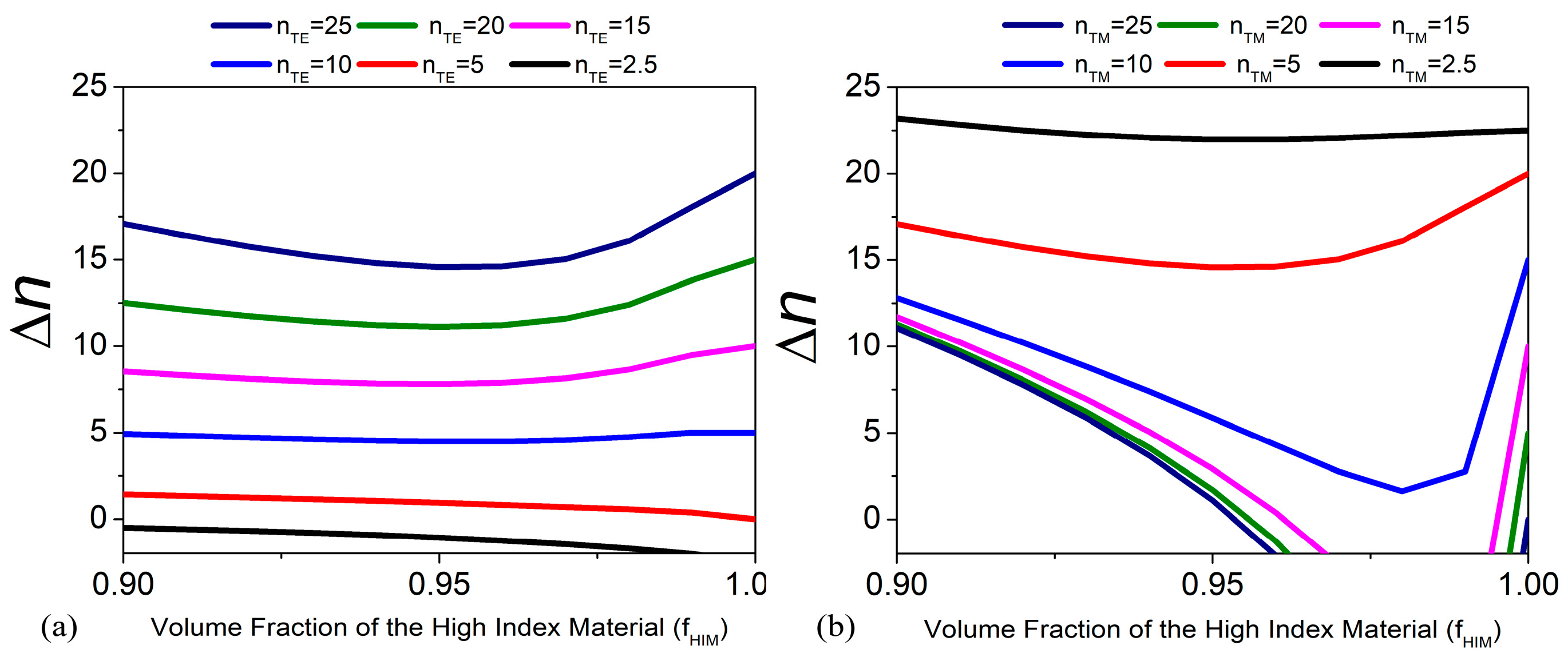
As shown in Figure 5b and Figure 6a, there is a turning point from a negative to a positive slope where a near-flat region of birefringence exists. This region between 0.9 and 1.0 of the volume ratios of the high index material is examined more thoroughly in Figure 7. It is clearly observed in Figure 7a that at a constant nTM = 5, the birefringence gradually increases as the nTE increases, which makes sense since the index contrast between the constituting materials should be high in order to obtain higher birefringence. The flat region is always around 0.95. Figure 7b shows the birefringence as a function of fHIM for constant nTE = 5 and varying nTM between 2.5 and 25. It is readily seen that for nTM = 2.5 and nTM = 5, there are flat regions of birefringence around fHIM ≈ 0.95. Therefore, the periodicity is chosen accordingly, with the metamaterial unit cell length restricted to around 240 μm, comprising 4 unit cells of 60 μm each. Additionally, the air groove length is restricted to approximately 10 μm to achieve the maximum birefringence at a volume fraction near 0.95.
It is worth noting that the form birefringence is constrained within the range defined by the refractive indices of the high and low index materials used in the structure (as an example for n1 = 5 and n2 = 25, the cut-off limits are 5 < Δn < 25). While higher form birefringence can be achieved at lower volume fractions, this approach would introduce a stronger frequency dependence.
The figures show that the birefringence can be significantly enhanced or reduced, depending on the index contrast and the polarization state of the impinging electromagnetic wave. This also has a strong effect on the frequency-dependent behavior of the birefringence achieved. This becomes a crucial adjustment not only for the periodicity length of the metamaterial but also for its orientation with respect to the air groove patterns used in the form birefringent system. The orientation of the designed unit cells would directly lead to an exchange of the refractive index values between the TE and TM modes. In other words, the nTE index values for the I-shaped configuration correspond to the nTM index values for the 90° rotated I-shaped configuration (or we can call it the H-shaped configuration), and the nTM index values for the I-shaped configuration correspond to the nTE index values for the H-shaped configuration.

3.4. Birefringence Properties of the Proposed Hybrid Material

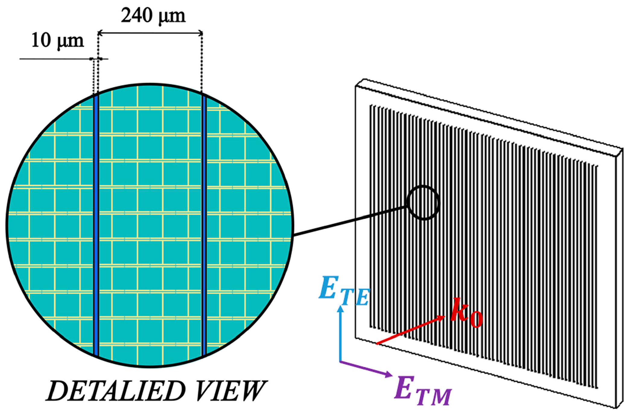
Here we investigate the form birefringence of the hybrid structure composed of alternating layers of 240 µm metamaterial and 10 µm air. A possible geometry of the designed device, which can be manufactured, is shown on the right side of Figure 8, as a square wave plate. The detailed view in Figure 8 illustrates the arrangement of the metamaterial and air groove components within the designed device.
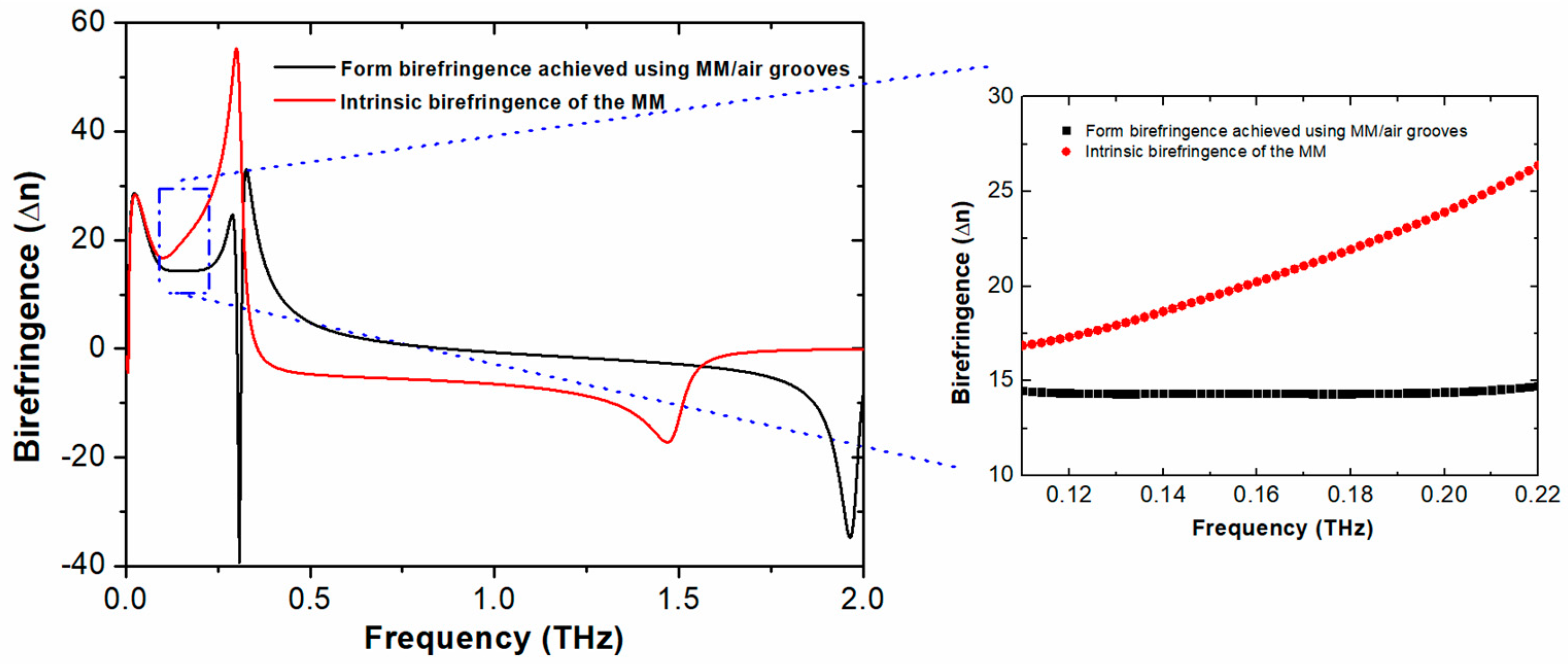
The effective refractive indices of the metamaterial under TE and TM mode excitation calculated in Section 3.2 are considered in the calculation process of the second-order effective optical material parameters of the hybrid birefringent system. The birefringence properties of the hybrid birefringent system are calculated based on the equations given in Section 2.3 and the results are provided in Figure 9 for its real part and in Figure 10 for its imaginary part. Since the investigated I-shaped metamaterial structure is anisotropic, its intrinsic birefringence is also included in Figure 9. It is apparent that the birefringence of the hybrid system shows an almost constant curve around 14 between the frequencies of 0.11 and 0.22 THz. On the other hand, the intrinsic birefringence of the MM is dominantly determined by the TE mode response of the effective refractive index of the metamaterial in this frequency range.
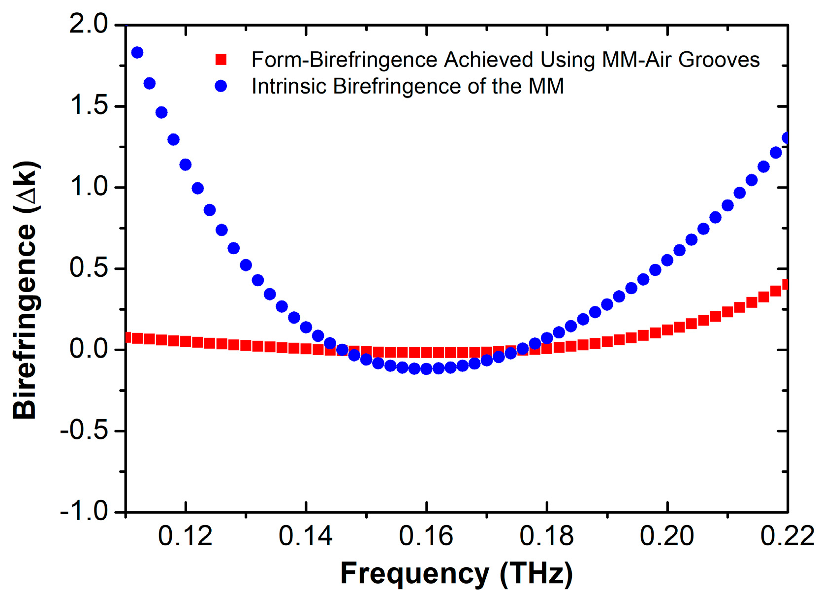
The imaginary part of the birefringence of the hybrid system as well as that of the metamaterial is depicted in Figure 10. The imaginary part of the birefringence is almost zero, varying between 0.07 and 0.45 at the interested frequency range (0.11–0.22 THz), where the real part of the birefringence is almost constant. The real part of the birefringence of the hybrid system is 14.3 at 0.16 THz, whereas the imaginary part of the birefringence is at its minimum value, almost zero. These results show that the proposed hybrid system is not only attractive for its extreme birefringence property that is not demonstrated before in the literature, but also the birefringence remains almost constant with almost zero loss in a 110 GHz frequency band range.

4. Conclusions

In this work, we have designed a hybrid material system that integrates the advantages of both metamaterials and form birefringence. Our results demonstrate the feasibility of achieving a birefringent medium that surpasses previous reports by three orders of magnitude while maintaining a time-invariant frequency response in the sub-terahertz range.
A high-refractive-index metamaterial design is adapted in the hybrid system design. This metamaterial serves as the anisotropic high-index material component of the hybrid form birefringent structure. We have thoroughly characterized it using simulations and analytical analysis. The extracted S-parameters of the metamaterial demonstrate an effective refractive index reaching 60 at 0.30 THz under parallel polarization and 17 at 1.47 THz under perpendicular polarization excitation. Later, the form birefringence concept was analytically examined under diverse conditions, taking into account both isotropic and anisotropic high-index materials, as well as the static case and the second-order EMT solutions. The results are used to provide a better understanding of the high and almost constant birefringence of around Δn~14 between 0.11 THz and 0.22 THz for the hybrid material structure.
We believe that the concept of form birefringence incorporating an anisotropic metamaterial holds significant promise and great potential for the development of numerous important, compact, versatile, and high-performance THz components and devices. This approach can enable the realization of innovative THz technologies with enhanced capabilities and improved performance characteristics, which could find widespread applications in various fields, such as telecommunications, sensing, imaging, and spectroscopy.

Author Contributions

All authors contributed equally to this work. Conceptualization, methodology, software, investigation, writing—original draft preparation, review and editing C.K. and F.B. All authors have read and agreed to the published version of the manuscript.

Funding

This research received no external funding.

Institutional Review Board Statement

Not applicable.

Informed Consent Statement

Not applicable.

Data Availability Statement

Data supporting the reported results of this study are available upon reasonable request from the authors.

Acknowledgments

The authors express profound gratitude to Prof. Dr. Ali Ulvi Yilmazer for his invaluable guidance and support during the formative physics studies of the authors in their first year of university, which sparked their lasting passion and enthusiasm for the field of applied physics.

Conflicts of Interest

The authors declare no conflicts of interest.

References

  1. Mantsch, H.H.; Naumann, D. Terahertz spectroscopy: The renaissance of far infrared spectroscopy. J. Mol. Struct. 2010, 964, 1–4. [Google Scholar] [CrossRef]
  2. Leitenstorfer, A.; Moskalenko, A.S.; Kampfrath, T.; Kono, J.; Castro-Camus, E.; Peng, K.; Qureshi, N.; Turchinovich, D.; Tanaka, K.; Markelz, A.G.; et al. The 2023 terahertz science and technology roadmap. J. Phys. D Appl. Phys. 2023, 56, 223001. [Google Scholar] [CrossRef]
  3. Yang, X.; Zhao, X.; Yang, K.; Liu, Y.; Liu, Y.; Fu, W.; Luo, Y. Biomedical Applications of Terahertz Spectroscopy and Imaging. Trends Biotechnol. 2016, 34, 810–824. [Google Scholar] [CrossRef]
  4. Jepsen, P.; Cooke, D.; Koch, M. Terahertz spectroscopy and imaging—Modern techniques and applications. Laser Photonics Rev. 2011, 5, 124–166. [Google Scholar] [CrossRef]
  5. Patil, M.R.; Ganorkar, S.B.; Patil, A.S.; Shirkhedkar, A.A. Terahertz Spectroscopy: Encoding the Discovery, Instrumentation, and Applications toward Pharmaceutical Prospectives. Crit. Rev. Anal. Chem. 2020, 52, 343–355. [Google Scholar] [CrossRef]
  6. Piccirillo, B.; Paparo, D.; Rubano, A.; Andreone, A.; Conti, M.R.; Giove, D.; Vicuña-Hernández, V.; Koral, C.; Masullo, M.R.; Mettivier, G.; et al. Liquid Crystal-Based Geometric Phase-Enhanced Platform for Polarization and Wavefront Analysis Techniques with the Short-TeraHertz FEL Oscillator TerRa@BriXSinO. Symmetry 2022, 15, 103. [Google Scholar] [CrossRef]
  7. Koral, C.; Mazaheri, Z.; Papari, G.P.; Andreone, A.; Drebot, I.; Giove, D.; Masullo, M.R.; Mettivier, G.; Opromolla, M.; Paparo, D.; et al. Multi-Pass Free Electron Laser Assisted Spectral and Imaging Applications in the Terahertz/Far-IR Range Using the Future Superconducting Electron Source BriXSinO. Front. Phys. 2022, 10, 725901. [Google Scholar] [CrossRef]
  8. Först, M.; Hoffmann, M.C.; Dienst, A.; Kaiser, S.; Rini, M.; Tobey, R.I.; Gensch, M.; Manzoni, C.; Cavalleri, A. THz Control in Correlated Electron Solids: Sources and Applications. In Terahertz Spectroscopy and Imaging; Springer: Berlin/Heidelberg, Germany, 2013; pp. 611–631. [Google Scholar] [CrossRef]
  9. Yang, H.; Zheng, S.; He, W.; Yu, X.; Zhang, X. Terahertz orbital angular momentum: Generation, detection and communication. China Commun. 2021, 18, 131–152. [Google Scholar] [CrossRef]
  10. Wang, H.; Song, Q.; Cai, Y.; Lin, Q.; Lu, X.; Shangguan, H.; Ai, Y.; Xu, S. Recent advances in generation of terahertz vortex beams and their applications. Chin. Phys. B 2020, 29, 097404. [Google Scholar] [CrossRef]
  11. Fickler, R.; Lapkiewicz, R.; Plick, W.N.; Krenn, M.; Schaeff, C.; Ramelow, S.; Zeilinger, A. Quantum entanglement of high angular momenta. Science 2012, 338, 640–643. [Google Scholar] [CrossRef] [PubMed]
  12. Gibson, G.; Courtial, J.; Padgett, M.J.; Vasnetsov, M.; Pas’ko, V.; Barnett, S.M.; Franke-Arnold, S. Free-space information transfer using light beams carrying orbital angular momentum. Opt. Express 2004, 12, 5448–5456. [Google Scholar] [CrossRef] [PubMed]
  13. Liu, K.; Li, X.; Gao, Y.; Wang, H.; Cheng, Y. Microwave imaging of spinning object using orbital angular momentum. J. Appl. Phys. 2017, 122, 124903. [Google Scholar] [CrossRef]
  14. Park, G.S.; Kim, Y.H.; Han, H.; Han, J.K.; Ahn, J.; Son, J.H.; Park, W.Y.; Jeong, Y.U. Convergence of Terahertz Sciences in Biomedical Systems; Springer: Dordrecht, The Netherlands, 2012; pp. 1–435. [Google Scholar] [CrossRef]
  15. Watanabe, S. Terahertz polarization imaging and its applications. Photonics 2018, 5, 58. [Google Scholar] [CrossRef]
  16. Nowack, T.S.; Shah, Y.D.; Escorcia, I.; Grant, J.P.; Kenney, M.; Pusino, V.; Faccio, D.; Wasige, E.; Cumming, D.R.S. Terahertz polarimetry with a monolithic metasurface. Opt. Lett. 2022, 47, 4199–4202. [Google Scholar] [CrossRef]
  17. Mazaheri, Z.; Koral, C.; Andreone, A. Accurate THz ellipsometry using calibration in time domain. Sci. Rep. 2022, 12, 7342. [Google Scholar] [CrossRef]
  18. Liu, M.; Li, M.; Jiang, C.; Yan, X.; Wan, Y. Research progress on high birefringence terahertz photonic crystal fibers. Laser Optoelectron. Prog. 2017, 54, 090006. [Google Scholar] [CrossRef]
  19. Wang, L.; Xiao, R.-W.; Ge, S.-J.; Shen, Z.-X.; Lü, P.; Hu, W.; Lu, Y.-Q. Research progress of terahertz liquid crystal materials and devices. Wuli Xuebao/Acta Phys. Sin. 2019, 68, 084205. [Google Scholar] [CrossRef]
  20. Wiesauer, K.; Jördens, C. Recent advances in birefringence studies at THz frequencies. J. Infrared Millim. Terahertz Waves 2013, 34, 663–681. [Google Scholar] [CrossRef]
  21. Ma, Y.; Shan, Y.; Cheng, Y.; Yang, R.; Kwok, H.-S.; Zhao, J. The Birefringence and Extinction Coefficient of Ferroelectric Liquid Crystals in the Terahertz Range. Photonics 2023, 10, 1368. [Google Scholar] [CrossRef]
  22. Hsieh, C.-F.; Lai, Y.-C.; Pan, R.-P.; Pan, C.-L. Polarizing terahertz waves with nematic liquid crystals. Opt. Lett. 2008, 33, 1174–1176. [Google Scholar] [CrossRef]
  23. Vieweg, N.; Shakfa, M.; Koch, M. BL037: A nematic mixture with high terahertz birefringence. Opt. Commun. 2011, 284, 1887–1889. [Google Scholar] [CrossRef]
  24. Sun, L.; Huang, L.; Wang, Y.; Lian, Y.; Huang, G.; Zhao, H.; Zheng, K. Ultra-Low Loss Graphene Plasmonic Waveguide for Chip-Scale Terahertz Communication. IEEE Photonics J. 2021, 13, 4800706. [Google Scholar] [CrossRef]
  25. Chen, M.; Sheng, P.; Sun, W.; Cai, J. A symmetric terahertz graphene-based hybrid plasmonic waveguide. Opt. Commun. 2016, 376, 41–46. [Google Scholar] [CrossRef]
  26. Massaro, A.; Cingolani, R.; De Vittorio, M.; Passaseo, A. Bragg reflector by means of the form birefringence effect in dielectric rings. Superlattices Microstruct. 2010, 47, 219–224. [Google Scholar] [CrossRef]
  27. Koral, C.; Mazaheri, Z.; Andreone, A. THz Multi-Mode Q-Plate with a Fixed Rate of Change of the Optical Axis Using Form Birefringence. Micromachines 2022, 13, 796. [Google Scholar] [CrossRef]
  28. Scherger, B.; Scheller, M.; Vieweg, N.; Cundiff, S.T.; Koch, M. Paper terahertz wave plates. Opt. Express 2011, 19, 24884–24889. [Google Scholar] [CrossRef]
  29. Wu, C.-J.; Chen, M.-S.; Yang, T.-J. Photonic band structure for a superconductor-dielectric superlattice. Phys. C Supercond. Its Appl. 2005, 432, 133–139. [Google Scholar] [CrossRef]
  30. Aly, A.H.; Ryu, S.-W.; Hsu, H.-T.; Wu, C.-J. THz transmittance in one-dimensional superconducting nanomaterial-dielectric superlattice. Mater. Chem. Phys. 2009, 113, 382–384. [Google Scholar] [CrossRef]
  31. Zhang, B.; Gong, Y. Achromatic terahertz quarter waveplate based on silicon grating. Opt. Express 2015, 23, 14897–14902. [Google Scholar] [CrossRef]
  32. Koral, C.; Mazaheri, Z.; Andreone, A. A Large Area Wide Bandwidth THz Phase Shifter Plate for High Intensity Field Applications. Photonics 2023, 10, 825. [Google Scholar] [CrossRef]
  33. Xiao, S.; Wang, T.; Liu, T.; Zhou, C.; Jiang, X.; Zhang, J. Active metamaterials and metadevices: A review. J. Phys. D Appl. Phys. 2020, 53, 503002. [Google Scholar] [CrossRef]
  34. Ali, A.; Mitra, A.; Aïssa, B. Metamaterials and Metasurfaces: A Review from the Perspectives of Materials, Mechanisms and Advanced Metadevices. Nanomaterials 2022, 12, 1027. [Google Scholar] [CrossRef] [PubMed]
  35. Kumar, N.S.; Naidu, K.C.B.; Banerjee, P.; Babu, T.A.; Reddy, B.V.S. A review on metamaterials for device applications. Crystals 2021, 11, 518. [Google Scholar] [CrossRef]
  36. Landy, N.I.; Sajuyigbe, S.; Mock, J.J.; Smith, D.R.; Padilla, W.J. Perfect metamaterial absorber. Phys. Rev. Lett. 2008, 100, 207402. [Google Scholar] [CrossRef]
  37. Bağci, F. A Terahertz Metamaterial Absorber-Based Temperature Sensor Having Nine Resonance Peaks. Gazi Univ. J. Sci. 2021, 34, 1163–1177. [Google Scholar] [CrossRef]
  38. Bagci, F.; Medina, F. Design of a wide-angle, polarization-insensitive, dual-band metamaterial-inspired absorber with the aid of equivalent circuit model. J. Comput. Electron. 2017, 16, 913–921. [Google Scholar] [CrossRef]
  39. Burokur, S.N.; Sellier, A.; Kanté, B.; de Lustrac, A. Symmetry breaking in metallic cut wire pairs metamaterials for negative refractive index. Appl. Phys. Lett. 2009, 94, 201111. [Google Scholar] [CrossRef]
  40. Valentine, J.; Zhang, S.; Zentgraf, T.; Ulin-Avila, E.; Genov, D.A.; Bartal, G.; Zhang, X. Three-dimensional optical metamaterial with a negative refractive index. Nature 2008, 455, 376–379. [Google Scholar] [CrossRef]
  41. Liu, Z.; Zhang, C.; Sun, S.; Yi, N.; Gao, Y.; Song, Q.; Xiao, S. Polarization-independent metamaterial with broad ultrahigh refractive index in terahertz region. Opt. Mater. Express 2015, 5, 1949–1953. [Google Scholar] [CrossRef]
  42. Choi, M.; Lee, S.H.; Kim, Y.; Kang, S.B.; Shin, J.; Kwak, M.H.; Kang, K.-Y.; Lee, Y.-H.; Park, N.; Min, B. A terahertz metamaterial with unnaturally high refractive index. Nature 2011, 470, 369–373. [Google Scholar] [CrossRef]
  43. Jing, X.; Gui, X.; Xia, R.; Hong, Z. Ultrabroadband Unnaturally High Effective Refractive Index Metamaterials in the Terahertz Region. IEEE Photonics J. 2017, 9, 59001077. [Google Scholar] [CrossRef]
  44. Konstantinidis, K.; Feresidis, A.P. Broadband near-zero index metamaterials. J. Opt. 2015, 17, 105104. [Google Scholar] [CrossRef]
  45. Jiang, L.; Fang, B.; Yan, Z.; Fan, J.; Qi, C.; Liu, J.; He, Y.; Li, C.; Jing, X.; Gan, H.; et al. Terahertz high and near-zero refractive index metamaterials by double layer metal ring microstructure. Opt. Laser Technol. 2020, 123, 105949. [Google Scholar] [CrossRef]
  46. Min, L.; Huang, L.-R.; Sun, R.; Xi, M.-M.; Li, Z.-W. Dual Metamaterial with Large Birefringence. IEEE Photonics J. 2015, 7, 4600608. [Google Scholar] [CrossRef]
  47. Jing, X.; Xia, R.; Gui, X.; Wang, W.; Tian, Y.; Zhu, D.; Shi, G. Design of ultrahigh refractive index metamaterials in the terahertz regime. Superlattices Microstruct. 2017, 109, 716–724. [Google Scholar] [CrossRef]
  48. Smith, D.R.; Schultz, S.; Markoš, P.; Soukoulis, C.M. Determination of effective permittivity and permeability of metamaterials from reflection and transmission coefficients. Phys. Rev. B—Condens. Matter Mater. Phys. 2002, 65, 195104. [Google Scholar] [CrossRef]
  49. Markos, P.; Soukoulis, C. Transmission properties and effective electromagnetic parameters of double negative metamaterials. Opt. Express 2003, 11, 649–661. [Google Scholar] [CrossRef]
  50. Chen, X.; Grzegorczyk, T.M.; Wu, B.-I.; Pacheco, J.J.; Kong, J.A. Robust method to retrieve the constitutive effective parameters of metamaterials. Phys. Rev. E—Stat. Phys. Plasmas Fluids Relat. Interdiscip. Top. 2004, 70, 016608. [Google Scholar] [CrossRef]
  51. Scheller, M.; Jördens, C.; Koch, M. Terahertz form birefringence. Opt. Express 2010, 18, 10137–10142. [Google Scholar] [CrossRef]
  52. Neff, C.W.; Summers, C.J. A photonic crystal superlattice based on triangular lattice. Opt. Express 2005, 13, 3166–3173. [Google Scholar] [CrossRef]
  53. Hernandez-Serrano, A.I.; Castro-Camus, E.; Lopez-Mago, D. q-plate for the Generation of Terahertz Cylindrical Vector Beams Fabricated by 3D Printing. J. Infrared Millim. Terahertz Waves 2017, 38, 938–944. [Google Scholar] [CrossRef]
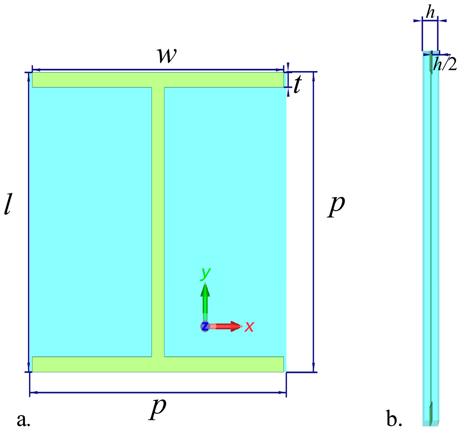
Figure 1. Schematic view of the unit cell of the metamaterial shown from (a) frontal and (b) lateral perspectives. Structural parameters of the unit cell are p = 60, w = 58.8, t = 3, l = 59.88, h = 2.45 (units in µm).
Photonics 11 00860 g001
Figure 2. Reflection and transmission spectra of the proposed metamaterial for normally incident THz waves under TE and TM mode excitation.
Photonics 11 00860 g002
Figure 3. The real and imaginary parts of the refractive index under (a) parallel and (b) perpendicular excitation of the metamaterial.
Photonics 11 00860 g003
Figure 4. Plots of the static (scatter symbol) and the 2nd order (line) form birefringence solutions with respect to the volume fraction of the isotropic metamaterial when effective refractive indices under TE and TM mode excitation range between 2.5 and 25.0. The color codes of the squares correspond to the line colors used for the respective refractive index values.
Photonics 11 00860 g004
Figure 5. Plots of the static (scatter symbol) and the 2nd order (line) form birefringence solutions with respect to the volume fraction of the material when effective refractive indices under TE mode excitation range between 2.5 and 25.0 while (a) nTM = 25 and (b) nTM = 5. The color codes of the squares correspond to the line colors used for the respective refractive index values.
Photonics 11 00860 g005
Figure 6. Plots of the static (scatter symbol) and the 2nd order (line) form birefringence solutions with respect to the volume fraction of the material when effective refractive indices under TM mode excitation range between 2.5 and 25.0 while (a) nTE = 25 and (b) nTE = 5. The color codes of the squares correspond to the line colors used for the respective refractive index values.
Photonics 11 00860 g006
Figure 7. Magnified plots highlighting the near-flat region of birefringence observed around the 0.95 volume fraction. The 2nd order form birefringence solutions with respect to the volume fraction of the material (a) with varying nTE values at a constant nTM = 5, (b) with varying nTM values at a constant nTE = 25.
Photonics 11 00860 g007
Figure 8. The scheme of the proposed hybrid birefringent system. The detailed design scheme depicts the arrangement of the metamaterial and air groove components within the device, featuring 4 unit cells spanning a length of 240 μm and a 10 μm gap between them.
Photonics 11 00860 g008
Figure 9. The real part of the birefringence calculated for the proposed MM/air grooves hybrid birefringence system and for the proposed metamaterial structure.
Photonics 11 00860 g009
Figure 10. The imaginary part of the birefringence calculated for the proposed MM/air grooves hybrid birefringence system and for the proposed metamaterial structure.
Photonics 11 00860 g010
Disclaimer/Publisher’s Note: The statements, opinions and data contained in all publications are solely those of the individual author(s) and contributor(s) and not of MDPI and/or the editor(s). MDPI and/or the editor(s) disclaim responsibility for any injury to people or property resulting from any ideas, methods, instructions or products referred to in the content.