1. Introduction
The rise of Internet of Things (IoT) technology has led to a notable increase in the deployment of automated robots and transporters within indoor settings such as factory warehouses and enclosed public spaces [
1,
2]. Achieving precise location awareness is crucial for these devices. Current Indoor Positioning Systems (IPSs) mostly rely on Radio Frequency (RF) technologies such as Ultra-Wideband (UWB) [
3], Wi-Fi [
4], or Bluetooth. However, these technologies have drawbacks, including significant energy consumption and limited precision up to meters or decimeters. Simultaneous Localization and Mapping (SLAM)-based systems offer an alternative but are expensive and require re-calibration if the scenario changes [
5].
Meanwhile, visible light technologies emerge as a cost-effective and accurate option with additional benefits like low susceptibility to multi-path effects and immunity to electromagnetic interference [
6], making it a potential candidate for various applications ranging from asset tracking in smart buildings to indoor navigation and data transmission in IoT networks. It enables simultaneous functionality for indoor navigation, data transmission, and illumination in indoor environments by leveraging the capability of LED lighting. By modulating light intensity at imperceptible speeds, these systems encode data or location information, which is then received by a Photodiode (PD) or Image Sensor (IS) at the receiving end, enabling precise localization and efficient communication. The PD-based techniques for indoor positioning include various algorithms such as received signal strength [
7], time of arrival, angle of arrival [
8], and fingerprinting [
9].
In camera-based IPSs, the position is determined by the coordinates of LEDs from captured images. Some of the techniques in the literature require a single camera to capture multiple LEDs on an image. Rêgo, M. et al. [
10] utilize four light sources as beacons and a smartphone as a receiver for indoor positioning. The system results in an average 2D error of 7.4 cm for a distance between the camera and the LEDs of 2.7 m. In [
11], the authors present positioning systems for both 2D and 3D scenarios utilizing different cameras. A mobile phone camera is employed for 2D positioning, whereas stereo vision cameras are used for 3D location. The system achieves accuracies of 1.97 cm and 2.6 cm for 2D and 3D respectively. Furthermore, in [
12], the authors analyze the impact of camera resolution on positioning accuracy. Experimental results demonstrate a positioning error of 6.3 cm with a resolution of 320 × 480 and of 2.1 cm with a resolution of 1280 × 2000.
To reduce the requirement of capturing multiple LEDs in the image, some approaches utilize an inertial measurement unit (IMU) along with the camera. In work [
13], the smartphone camera captures the images, and the required angle information is calculated through IMU, and utilized to estimate the receiver’s position, resulting in an average 3D positioning error of 5.44 cm at a height of 1.75 m. In [
14], a Visible Light Positioning (VLP) system with a camera, a LIDAR, and an IMU sensor is proposed for 3D positioning, resulting in an average 3D positioning error of 6.5 cm. Though these approaches reduce the infrastructure needs, they lose precision. The use of extended Kalman filters (EKFs) can improve the location accuracy as demonstrated in [
15,
16]. In [
15], a loosely coupled VLP–inertial fusion method based on the extended Kalman filter is proposed, demonstrating a mean 3D positioning error of 2.7 cm at a height of 2.5 m. In [
16], the authors employ the sensor fusion approach using the EKF, the Particle Filter (PF), and combined filters (EKF and PF). The combined method achieves a mean 2D positioning accuracy of 2 cm at a height of 1.5 m. In conclusion, integrating additional hardware with image sensors enhances the positioning accuracy but also increases the system’s cost and complexity.
The utilization of multiple cameras for visible light transmissions offers significant advantages for indoor IoT applications, particularly in terms of enhanced data transfer rates. Our work, as detailed in [
17], focuses on harnessing these benefits through the design and implementation of a cost-effective multi-camera system (MCS). The system achieves improved bit-rate transmission capabilities by employing multiple cameras compared to traditional single-camera setups. Furthermore, leveraging several cameras can enable the provision of location capabilities without the need for additional hardware. Thus, this work capitalizes on the existing communication infrastructure to provide accurate location services without incurring additional deployment costs. This dual functionality is a key aspect that maximizes the utility of the infrastructure investment. In this paper, we will go into the details of this approach, showing its feasibility and effectiveness.
Moreover, to the author’s knowledge, only two related works explore the utilization of MCS for Visible Light Positioning as presented by Jiaqi et al. [
18,
19]. In their initial work [
18], the authors present a VLP system based on dual cameras. In the most recent work [
19], the arrangement is expanded to three cameras. While attaining an exceptional accuracy of 0.17 cm, this achievement depends on the use of costly cameras with a resolution of 4000 × 3036 pixels. The experimental setup covers an area of 1 × 1 m, and the cameras tilted towards the center of the target enhance the accuracy but limit coverage area, which does not reflect practical applications. Finally, the authors have explored 3D positioning but have not included accuracy tests at various heights, which could be valuable for comprehensive evaluation.
To this end, the positioning accuracy of most systems does not exceed 2 cm, with some still limited to 2D positioning. Moreover, the above systems either depend on multiple LEDs, additional hardware, or high-resolution images for precise results. An image resolution directly defines the level of detail captured: a higher resolution yields more pixels and finer details. However, adopting hardware capable of capturing such detail comes with higher costs and longer processing time.
Table 1 summarizes the results of these studies, including details on the type and the cost of the receiver, image size, average accuracy, and coverage area.
In this work, we leverage the low-cost multi-camera setup developed for indoor data transmission, as outlined in [
17], to facilitate 3D positioning. The system design incorporates a single LED for transmitting a VLP signal. Multiple image sensors, mounted on the ceiling at the receiver end, capture the transmitted signal. The advantage of employing a ceiling-mounted camera lies in its reduced intrusiveness, effectively mitigating privacy concerns by capturing fewer detailed facial features and personal identifiers compared to horizontally tilted cameras. It also benefits from a clearer line of sight, minimizing the chances of obstructed views that could disrupt data capture and analysis. Furthermore, this type of system generally demands less calibration and adjustments, ensuring consistent and dependable performance. With this aim, it is important to note that this research solely focuses on 3D indoor positioning, leaving the potential for the implementation and exploration of joint illumination, communication, and localization for future publications. The main contributions of this research are as follows:
Firstly, a non-integer pixel algorithm is proposed to improve precision in front of using higher resolution images. This enables the system to capture precise light coordinate details without relying on resolution enhancement, thereby facilitating more accurate positioning.
Secondly, we present an algorithm that utilizes the precise coordinate details obtained from the first algorithm to determine the 3D position of an object. With high accuracy, reduced system cost, and low complexity, the proposed system can be efficiently implemented on low-end hardware platforms, providing good precision even in front of errors in the object’s projection on the images, consequently increasing the adaptability and feasibility of VLP technologies across various scenarios.
To this end, besides this introduction and background, the paper contains four sections as follows.
Section 2 gives an overview of the system design, covering the detailed non-integer pixel and 3D positioning algorithms.
Section 3 analyzes the experimental results covering the system setup and the results from the validation of the proposed algorithms.
Section 4 discusses the main findings and the results.
Section 5 concludes the paper and outlines potential future directions for further research and improvements.
2. System Design
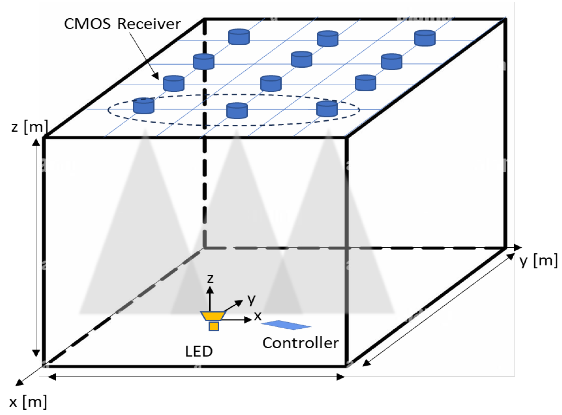
Figure 1 shows the design of the proposed system consisting of a single LED at the transmitter (Tx) end sending the VLP signal using a modulation technique. At the receiving end (Rx), multiple image sensors with onboard processors fixed on the ceiling capture the transmitted signal. Initially, the image is captured in JPG format and then decompressed to obtain raw RGB values. The intensity value of pixels is derived from their RGB values by combining the three components. This intensity is often referred to as luminance or brightness and is typically measured on a scale from 0 to 255 in 8-bit images. After decompression, the image data, initially in a 1D array, are restructured into a 2D format according to the image’s dimensions. A threshold value is then applied to differentiate regions of interest, such as light spots, from the rest of the image. If the intensity exceeds the threshold, the coordinates of those pixels are identified on the image plane.
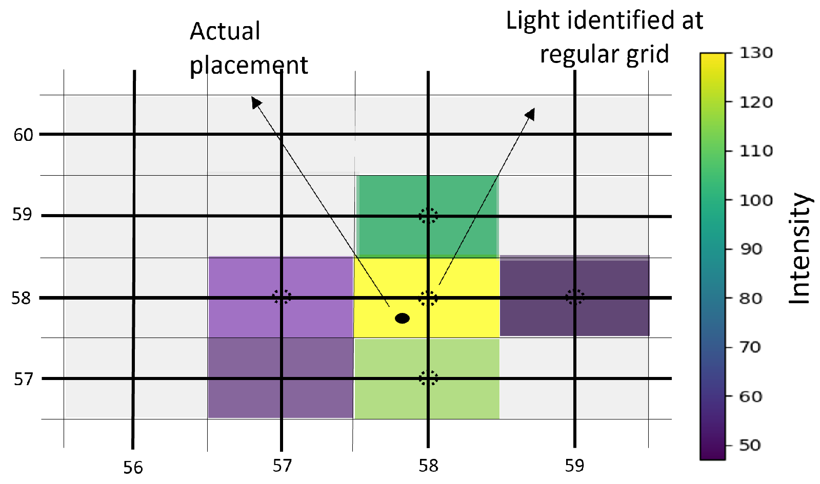
Achieving precise positioning of the light spot on an image plane is important to ensure optimal measurement accuracy. For instance, in a system with lower resolution and increased separation between the Tx and Rx end, the inter-pixel distance on an image plane may exceed a centimeter. In such scenarios, the actual placement of light at an integer number of pixels is not always the case as shown in
Figure 2. A new non-integer coordinate must be derived to determine the light position accurately. Therefore, a simple algorithm is adopted to achieve a better light spot position on an image plane. This algorithm can be implemented on embedded devices without requiring high CPU resources.
2.1. Non-Integer Pixel Algorithm
This section outlines an approach to approximate non-integer coordinates by utilizing the pixel with maximum intensity and its surrounding pixels.
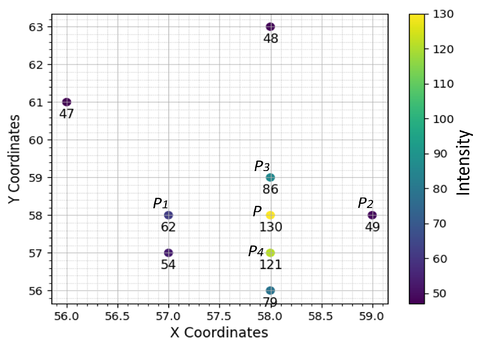
Figure 3 illustrates the plotting of pixel coordinates on the image grid. The technique involves detecting the highest intensity point
using a threshold method. Once identified, the algorithm focuses on the surrounding pixel points within a defined region of interest around
P.
The neighboring pixels
and
are considered on the x-axis, as depicted in
Figure 3, and
and
on the y-axis. The average intensities of three consecutive points are calculated, and values are linearly distributed along each point to obtain equal distances between pixels. For instance, the average intensity between
,
P, and
is calculated as:
Let
be the coordinate of
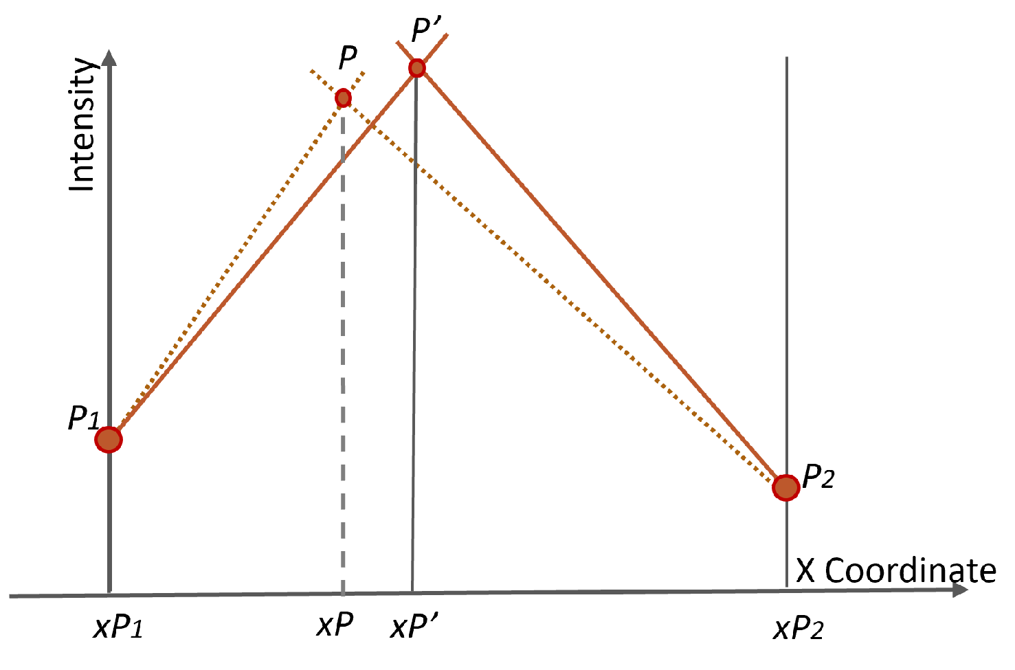
P on a regular grid. Assuming the actual point placed at
as shown in
Figure 4, the lines connecting the points
to
and
to
are given as:
Solving Equations (2) and (3) simultaneously, we obtain the
as
The calculation procedure of the vertical direction is the same as that of the horizontal direction as shown in
Figure 5.
To this end, the above decimal coordinates are then used for the next algorithm to ascertain the 3D position of the light source.
2.2. 3D Positioning Algorithm
This section outlines the positioning method for calculating the LED world coordinates.
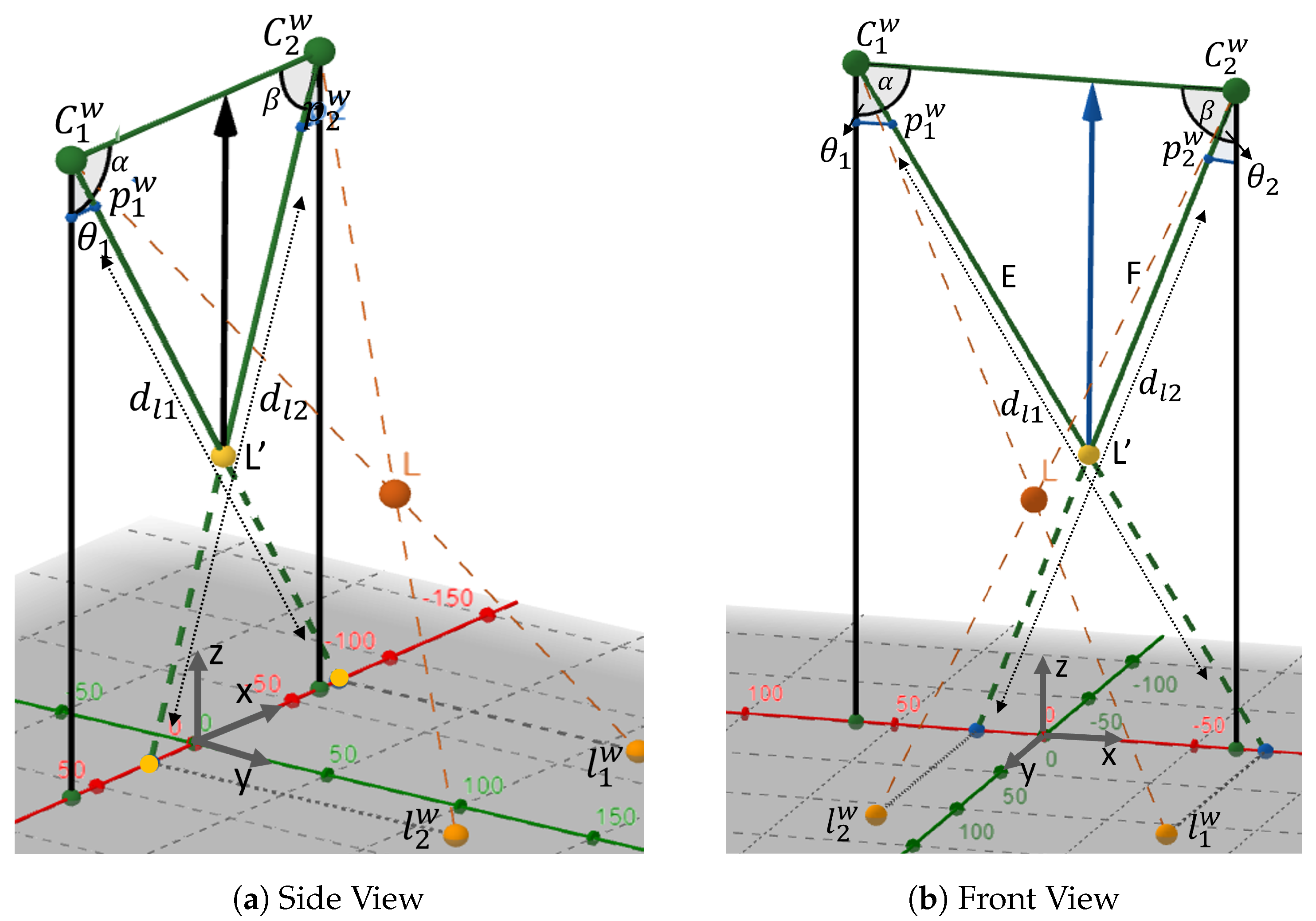
Figure 6 shows the positioning plane with a single light source and two image sensors. We set up a Camera Coordinate System (CCS) for Camera 1 and Camera 2 as
and
, respectively, to determine the 3D coordinates of the LED. In the CCS, the origins
and
serve as the optical centers, while
Z corresponds to the optical axes of Cam1 and Cam2.
For ease of representation, the World Coordinate System (WCS) coordinates of , , and L are expressed as , , and , respectively. The projection points of the LED onto the reference plane are denoted as points and , and their coordinates are represented as and , respectively. Similarly, the projection points of the LED onto the image plane are denoted as points and , with coordinates and , where and correspond to the focal lengths of Camera 1 and Camera 2, respectively.
In CCS, the points
and
are represented as:
To standardize across different coordinate systems,
and
are transformed into the WCS using scaling coefficients
and
:
Now, the points
and
in WCS are represented as:
The lines passing through
to
and
to
are expressed as:
To determine the
coordinates of point
L, we identify the intersection point of
and
. Hence, the LED coordinates
and
are calculated as:
To determine the depth of the LED, we assume points
and
along the y-axis; hence, the new point can be expressed as
. Given the projection points
and
onto the image planes and considering the analogous triangles between the image plane and the WCS plane, the values of
and
are determined as:
where
and
are the distance from optical center to
and
, respectively,
With this, the angles between the optical centers and projection points are calculated as:
Subsequently,
is given by
, and
is given by
. Considering the triangle
, the distance between
and
is denoted as
B, and the distances between
and
, as well as
and
, are denoted as
E and
F, respectively, as shown in
Figure 7.
Given the angles
and
, along with the baseline distance
B between the cameras, the two sides of the triangle are determined by the following expressions:
Similarly, the distance between baseline
B and point
represents the depth
of the LED point in WCS, calculated as:
or
3. Experimental Result and Analysis
3.1. Experimental Setup
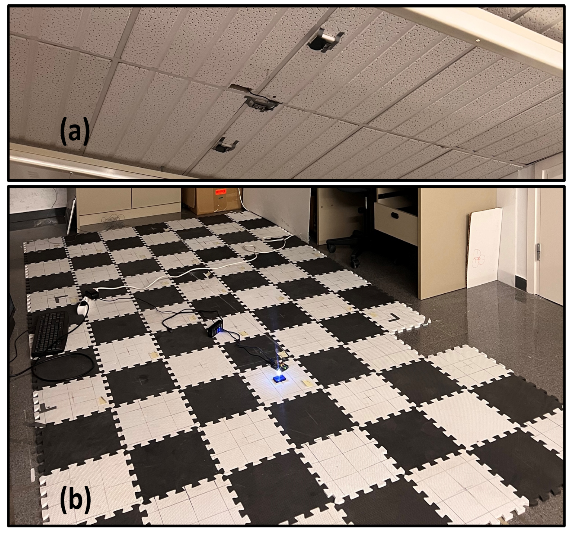
In this study, we present a real experimental setup, depicted in
Figure 8. To validate the system’s performance, we conduct various experiments, employing one to three cameras mounted on the ceiling with a view parallel to the floor. The experimental area spans 360 × 180 cm
2, with a single camera having a view of 240 × 180 cm
2 and a pair of cameras covering a shared field of view of 120 × 180 cm
2. Multiple test points are selected on a regular grid for each experiment. Further details of the experimental configurations are outlined in
Table 2.
Following the 2D calculation of LED coordinates using the proposed non-integer algorithm, these values are utilized to compute the third dimension employing the 3D algorithm. We evaluate the positioning accuracy by quantifying the 3D positioning error.
3.2. Non-Integer Positioning Accuracy
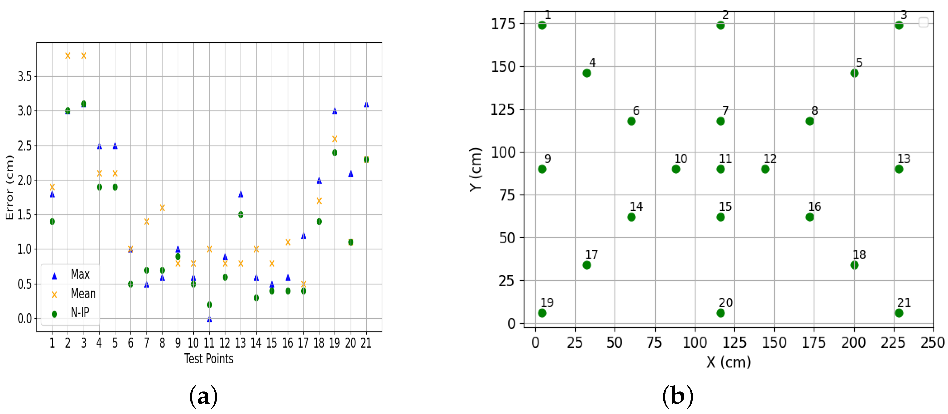
To assess the performance of the proposed non-integer pixel algorithm, we conducted tests by placing an LED at 21 different points on the floor, maintaining a vertical distance of 230 cm between the camera and the light source. A single camera was utilized for this experiment, with its placement indicated by a small circle at the center in
Figure 9. The objective of these tests was to evaluate the algorithm’s accuracy in determining 2D positions by precisely locating the LED on the image plane. Multiple tests were performed for each case to validate the algorithm’s performance.
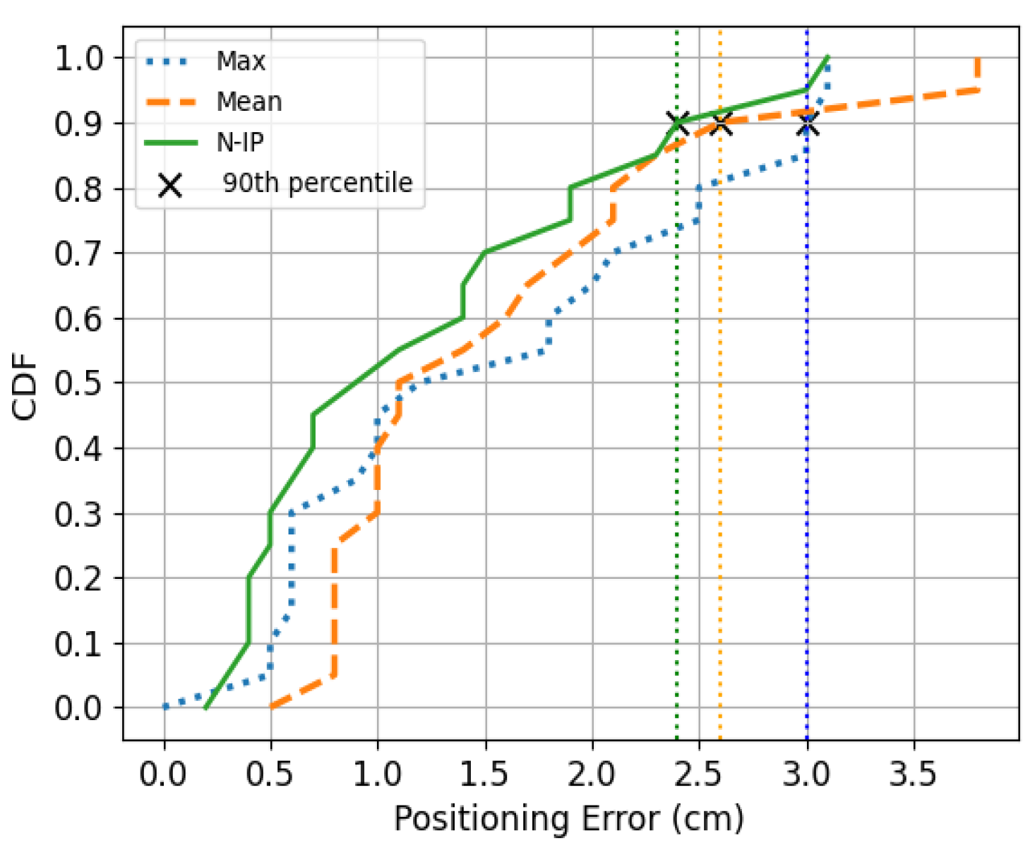
Three different approaches are considered to obtain the position of the LED: (a) the highest, where the LED position is determined based on the pixel with the highest intensity value in the image; (b) the mean, where the LED position is calculated by averaging the positions of the two pixels with the highest intensity values; and (c) the non-integer, which employs the proposed algorithm.
Figure 9 illustrates the positioning errors (PEs) obtained from these approaches. For a clearer analysis,
Figure 10 and
Figure 11 show comparative analysis and cumulative distribution (CDF) for each method.
The errors associated with the highest integer range from 0 to 3.1 cm, with an average of 1.5 cm. For mean integer errors, the range expands from 0.5 to 3.8 cm, also with an average of 1.5 cm. Meanwhile, the PE obtained through the non-integer pixel algorithm ranges from 0.2 to 3.1 cm, with an average of 1.2 cm. Additionally, we compute the 90th percentile as detailed in
Table 3. Comparatively, the non-integer technique provides better average accuracy when compared to the highest and mean methods. Moreover, when employing the non-integer algorithm, 90% of errors remain below 2.5 cm.
3.3. Three-Dimensional Positioning Accuracy
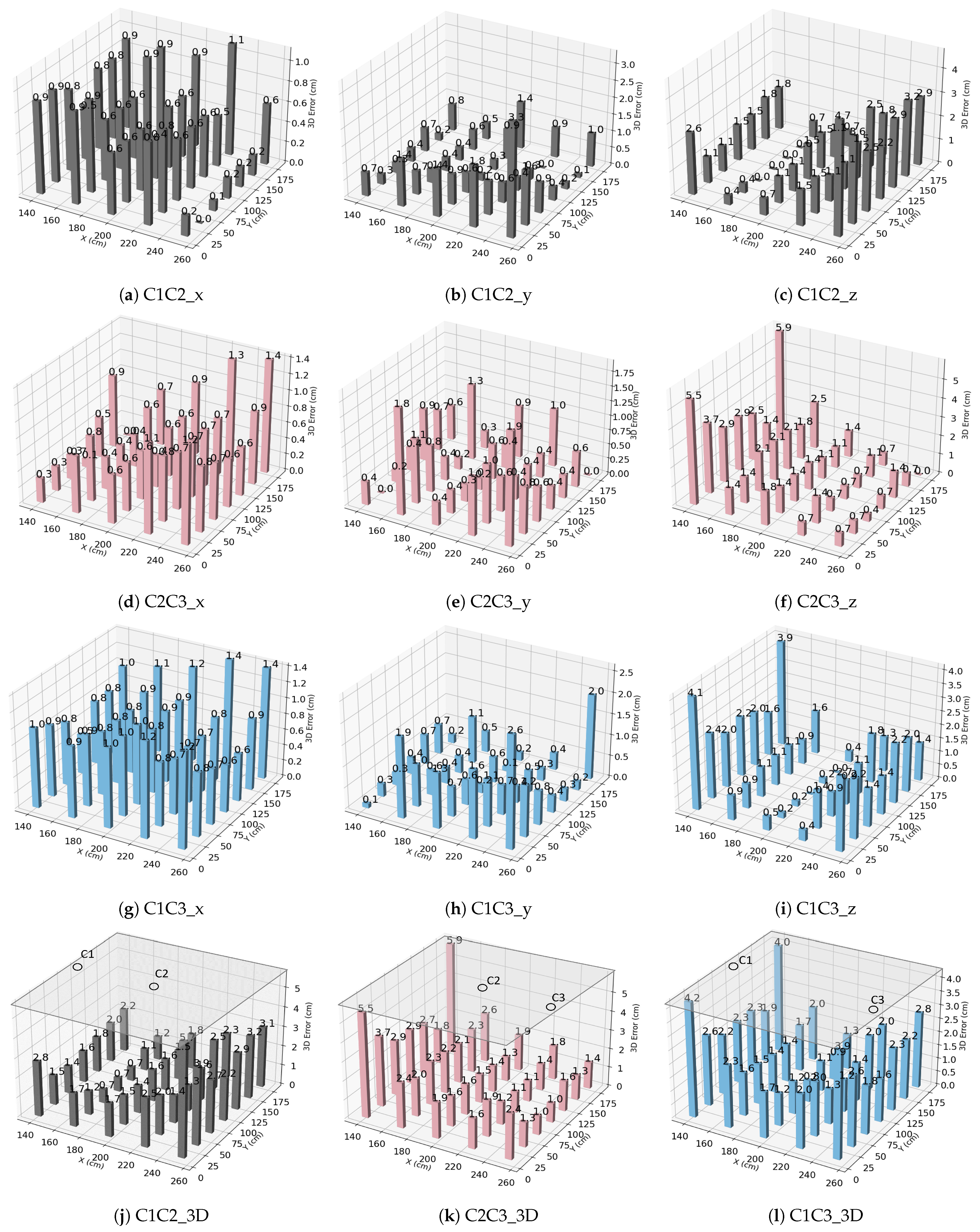
To validate the accuracy of the proposed 3D positioning algorithm, we first set up a configuration with two cameras, C1 and C3, working as a pair. Subsequently, a third camera C2 is placed in the middle to form a straight-line arrangement. Following this setup, camera pairs are established—C1C2, C2C3, and C1C3—representing side-to-center and side-to-side configurations. Due to the symmetry of the scenario, the results obtained from the C1C2 combination should align with those from C2C3. This secondary measurement serves to validate the system’s performance.
Figure 12 illustrates the error distribution across the X, Y, and Z coordinates and the 3D positioning errors derived from each camera pair. The errors in X and Y exhibit rough symmetry, while there exist some outliers associated to various factors such as imperfections of the low-cost camera optics, imprecise camera placement, or slight inclination of the camera lens. Although correcting these errors is theoretically possible, this can be costly on a real deployment. Rectifying camera distortion involves measuring the camera matrix to remove distortions from the image, a complex operation to implement on the used camera processor; thus it is omitted. Additionally, leveling the camera is also challenging due to its small size. Thus, the provided results serve to illustrate the performance of a realistic system that could be deployed, taking into account the challenges of the real scenario.
To compute the final 3D error, the following approaches are considered. (a) Taking the average of all camera pairs: This method offers a comprehensive assessment of the system’s performance across various points. It helps compensate for errors resulting from different camera positions or perspectives in a simple manner, without requiring specialized knowledge of the scenario. However, this approach may not accurately capture all positions and could potentially obscure outlier errors from specific camera pairs. (b) Selecting the nearest camera pair to points: Each pixel on a camera’s image sensor represents a portion of the scene. However, the geometry of camera lenses introduces distortion at the image edges, which can affect accuracy. This method involves choosing the pair of cameras physically closest to the point being localized. By prioritizing measurements from viewpoints closest to the target points, we would expect more accurate results for those specific points. Additionally, it may help to mitigate errors caused by occlusion and perspective distortion, which tend to increase with distance. However, it is important to note that points directly beneath the camera projection may still display larger errors due to perspective distortion. (c) Selecting the camera pair based on a predefined region: After deploying the system and taking measurements, it is evident that not all camera pairs perform equally well in every region of the space. Some pairs may provide more accurate results within certain predefined areas. So, instead of using any arbitrary camera pair, we select the pair known to perform better within the specific regions. This selection is based on prior knowledge and experimental data indicating which camera pairs are more suitable for particular areas. This approach optimizes the selection of camera pairs to enhance accuracy or performance within predefined areas, potentially leading to more precise 3D measurements.
The results from the above approaches are shown in
Figure 13, and a summary is provided in
Table 4. The average errors in both the x and y directions for each camera pair do not surpass 1 cm, and the average error in the z dimension is under 2 cm. The mean 3D error for approaches (a), (b), and (c) are 2 cm, 1.5 cm, and 1.4 cm, respectively.
3.4. Effect of System Parameters
Multi-camera systems are integral to various applications requiring precise spatial localization, such as robotics, and virtual reality. Understanding how the number and arrangement of cameras influence positioning accuracy is essential for optimizing the system design and performance. In this experiment, we investigate the effect of system parameters on positioning error, particularly focusing on camera spacing, the number of cameras, and their distribution.
3.4.1. Effect of the Number of Cameras
With the three cameras C1, C2, and C3, there exist three pairs: C1C2, C2C3, and C1C3. We conducted experiments by combining these various camera pairs to assess their impact on positioning accuracy.
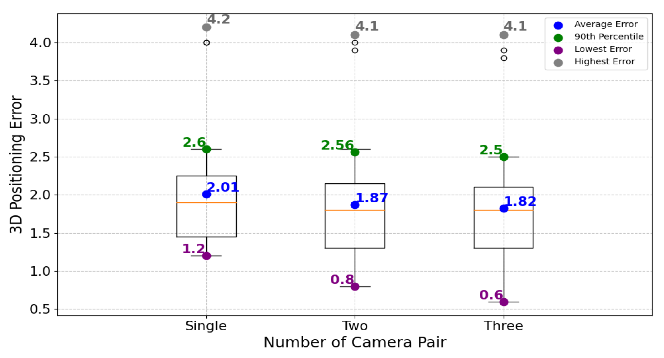
Figure 14 illustrates the positioning errors for single camera pair, two camera pair, and three camera pair configurations. When utilizing a single pair of cameras, the average error is 2 cm. This error slightly decreases to approximately 1.9 cm when employing two camera pairs and diminishes to roughly 1.8 cm with three cameras. Increasing the number of camera pairs from one to three leads to a slight reduction in positioning error, demonstrating the incremental improvement in accuracy achieved through multi-camera configurations.
3.4.2. Effect of Camera Spacing
We have analyzed the camera location to derive implications on 2D and 3D location accuracy.
Figure 9a–c give results on the different algorithms estimate 2D location from the image captured by the cameras. These figures also show how accuracy depends on the angle of view from the camera to the device. We can observe that as the angle of view increases, accuracy degrades. This is expected considering the poor quality of the optics.
Figure 12 introduces the usage of two cameras needed to determine the 3D location. In this case, we use cameras close to each other (at the edge of the area and in the middle) or separated (one camera at each side). We can observe that areas close to the center of the two cameras show better accuracy.
Combining the 3D locations seen by a pair of cameras helps to improve the accuracy in relation to the usage of only two cameras. Also, accuracy degrades in areas close to the borders or parallel to the central axis where cameras are located. In the final study, we compare the straight-line organization of the three cameras with a circular organization (
Figure 15a,b). We observe a more regular accuracy among the different location points with the circular deployment. However, a general conclusion about this will require a larger coverage area for deploying cameras in groups of three.
3.4.3. Effect of the Camera Arrangement
Figure 15 depicts the distribution of 3D positioning errors with various camera arrangements. The small circle in each figure represents the camera placement. In
Figure 15a, three cameras are arranged linearly along the x-axis, covering an area of 120 × 180 cm, resulting in an average error of 1.83 cm. The analysis shows that points closer to the center (at 90 × 45 cm) exhibit lower errors, maintaining an average error of 1.4 cm.
Figure 15b shows the distribution of errors with the cameras placed equidistantly in a triangular configuration covering an area of 150 × 90 cm. The errors within a radius of 45 cm reach 1.2 cm. Hence, with the current arrangement, the triangular configuration offers slightly better average accuracy than the linear arrangement. In a real deployment, these camera layouts could be extended to cover the entire surface. This would provide redundancy between the deployed areas and help to improve the errors observed at the edges, as these points would be in the vicinity of other cameras. In this respect, the results obtained in the central part (e.g., the inner part of the circle in the triangle arrangement) can be extrapolated to larger deployments.
In a broad comparison between the two arrangements where the cameras are placed at equal distances, the linear (square) arrangement outperforms the triangular one. On a larger surface, the triangular setup requires fewer cameras, resulting in a lower coverage density compared to the square setup. However, the worst-case precision (at the furthest distance) is still better with the square arrangement than with the triangle. This implies that while the triangular configuration may offer efficiency in terms of camera utilization, especially for larger surfaces, the square arrangement provides more consistent and accurate results across various scenarios. Ultimately, the choice between arrangements depends on specific application needs regarding accuracy, coverage area, and resource efficiency.
3.4.4. Effect of Height
As the height (h) of the object increases, it moves closer to the cameras, and the distance between the object and the cameras decreases. For this experiment, three cameras placed in a linear configuration were utilized, and 35 different test points from previous tests were selected.
Figure 16 illustrates the 3D error distribution at various object heights. With increasing h, there is a degradation in the accuracy obtained characterized by an increase in positioning errors. This degradation can be attributed to the movement of the object inside the image towards the edges of the camera lenses.
4. Discussion
This work presents a cost-effective multi-camera-based VLP system for 3D indoor positioning. Leveraging the existing communication infrastructure, this system offers location services without incurring additional deployment costs. A non-integer pixel algorithm is implemented to achieve the improved 2D positioning of objects without the need for high-resolution cameras and costly processing. The adoption of low-resolution cameras not only reduces costs but allows fast processing on cameras with embedded processors. The processing speed is sufficient to offer 50 locations per second, meeting the demands for tracking autonomous guided vehicles. A 3D algorithm utilizes the precise coordinate data acquired to determine the 3D positioning of objects. The algorithm derives x, y, and z coordinates from images captured by two cameras. It provides a solution even compensating for errors in the x and y coordinates of the object projection. The system achieves, with cameras with less than 20k pixels, a level of precision similar to solutions with 3M pixels and worse than others that employ 12M pixels cameras. Experimental results demonstrate an average 3D positioning error of 1.4 cm with cameras located at the ceiling and separated 2.3 meters from the floor. The positioning accuracy achieved by our solution is significantly better than other similar solutions such as those reported in [
10,
11,
12,
13,
14,
15,
16], which range from 7.4 to 2.6 cm. The devices can be placed on the floor or at a height of 15, 35 and 70 cm. As expected, increasing the height degrades precision, ranging from 1.02 cm in the best-case scenario (object on the floor) to 3.4 cm for 70 cm.
As the original system was conceived for Visible Light Communication (VLC) with several cameras to enhance the communication bit rate, the system benefits from the multiplicity of cameras to determine the 3D location. The cameras and their combination provide better precision. However, the camera’s setup and even the camera’s optics result in additional errors in the 3D location that are challenging to suppress. To minimize these errors, one of the combination methods developed uses a simple calibration, consisting of selecting a camera pair depending on a draft estimation of the x and y coordinates. Additionally, by combining more than two cameras, a study about the optimal camera placement has been conducted. It is observed that for the covered area, a triangular camera placement provides better results compared to a linear deployment (three cameras positioned along a line). The generalization of the results for larger areas with more cameras shows that a square grid of cameras offers better precision than a triangular one. Finally, it is observed that averaging the locations provided by different pairs of cameras reduces errors, but the advantages become almost negligible when using more than four cameras as indicated by the results obtained from 1, 2, and 3 pairs of cameras. In summary, the work presented in this paper introduces a VLP method that is cost effective, easy to deploy, reliable, and offers competitive performance. The solution is not merely a laboratory testbed but rather closely resembles real-world deployment.
5. Conclusions and Future Work
Visible light technology significantly advances indoor IoT applications by enabling lower power consumption, utilizing simple transceivers, and providing better location services. However, many systems still struggle with accuracy, often limited to a few centimeters despite using costly high-resolution cameras. This work presents a low-cost visible light system for 3D positioning that improves accuracy with low-resolution images. We propose a NI-P algorithm, allowing the system to accurately locate the light spot coordinates. A second algorithm then uses these precise coordinates to determine 3D positions, even with measurement errors. Our system offers high accuracy, reduced cost, and low complexity, making it suitable for low-end hardware platforms. Experimental results show an average 2D positioning error of 1.08 cm and a 3D error within 1.4 cm at a 2.3 m distance between the object and camera, with a 20 ms average positioning time on a low-end device. This system provides a good solution for building battery-powered or energy-harvesting devices and offers fast location tracking to cover moving devices that require guidance.
Several directions have been identified as future work. Firstly, characterizing precision based on camera resolution. While an increase in resolution is anticipated to enhance precision, it may still be constrained by intrinsic errors as previously discussed. Secondly, we intend to explore the influence of the camera’s field of view, which ranges from 60 to 160 degrees. A wider field of view, such as 160 degrees could potentially reduce the required number of cameras. However, it can also introduce errors due to pixel size and optical distortion, potentially resulting in a higher location error. Thirdly, we aim to investigate the use of retroreflectors as an alternative to LEDs. Retroreflectors are passive elements that reflect light back to its source. However, they are limited by a narrower angle of reflection, typically below 80 degrees, and require a lighting device close to the camera for optimal performance. Lastly, we will investigate the system’s capabilities for joint illumination, data transmission, and positioning services. This holistic approach aims to leverage the system for simultaneous functionalities, potentially enhancing its utility and versatility.
