Article

Coalitional Game Theory-Based Resource Allocation Strategy for Robust IRS-VLC System

by
Changling Liu
1,†,
Jianping Wang
1,†,
Lifang Feng
1,*,†,
Huimin Lu
1,†,
Haijian Sun
2,† and
Rose Qingyang Hu
3,†
1
School of Computer and Communication Engineering, University of Science and Technology Beijing, Beijing 100083, China
2
School of Electrical and Computer Engineering, University of Georgia, Athens, GA 30602, USA
3
Electrical and Computer Engineering Department, Utah State University, Logan, UT 84322, USA
*
Author to whom correspondence should be addressed.
These authors contributed equally to this work.
Photonics 2024, 11(6), 582; https://doi.org/10.3390/photonics11060582
Submission received: 28 May 2024 / Revised: 14 June 2024 / Accepted: 17 June 2024 / Published: 20 June 2024

Abstract

:
This study investigates the optimization of energy efficiency in robust visible light communication (VLC)—intelligent reflecting surface (IRS) systems through a novel resource allocation strategy based on coalitional game theory. By employing coalitional game theory, the proposed strategy optimizes LED power and IRS energy consumption within practical constraints. IRS elements form coalitions centered around a central unit or units, enhancing the system performance through coordinated element management. Simulation results demonstrate significant improvements in energy efficiency and signal quality compared to conventional methods, validating the effectiveness of the proposed strategy.

1. Introduction

Visible light communication (VLC) technology is considered a highly promising technology for future wireless communication networks. It has several distinct advantages, including non-electromagnetic interference, high safety, and cost-effectiveness [1]. However, it can be obstructed, leading to a significant decrease in the reliability of the line-of-sight (LOS) link. Furthermore, the power limits of cellular user devices also affect the performance of VLC systems. Researchers have studied controllable fields of view (FOVs), angle diversity receivers, orientation-adjustable receivers (OARs), and other visible light system robustness improvements. Recent innovations include intelligent reflecting surfaces (IRSs), which are both cost-effective and energy-efficient. IRSs are an emerging technology that leverages non-line-of-sight (NLoS) paths to boost system performance, and specular reflection is considered the primary NLOS component, while diffuse reflection is generally ignored [2]. An IRS has plenty of passive elements that can independently reflect incident signals to receivers [3]. The integration of IRSs into RF communication systems has been extensively studied to enhance wireless propagation and quality [4]. IRS arrays are well recognized for their effectiveness in compensating for line-of-sight (LOS) links [5,6]. In addition, an IRS consumes less energy compared to an amplify-and-forward relay for signal transmission. Utilizing IRSs to enhance both the reliability and energy efficiency (EE) of communication systems is promising. The authors of [7] optimized both the beamformer at the base station and the controllable phases of impinging signals at the RISs to maximize the minimum harvested energy among all devices. In [8], the authors optimized the beamforming at the access point (AP) and the phase vector of the RIS elements to maximize the weighted sum-rate of all users. The deployment of RISs for a network that consists of multiple users and a multi-antenna BS was investigated in [9], where the authors maximized the EE of mobile users by jointly optimizing the transmit power allocation and the phase shifts of the surface reflecting elements. IRS-RF approaches are not applicable in a downlink VLC system due to its unique properties. Transmitted signals must be non-negative and also be limited by a peak optical intensity. Mirror arrays or meta-surfaces can be used to implement IRS-VLC. AM Abdelhady et al. [10] proved that the performance of the mirror array is better than a metasurface in VLC system. It can reconfigure its signal reflection characteristics through micro-electronic mechanical systems (MEMSs) [11]. Several recent studies have focused on IRS deployment in VLC. The LOS obstruction problem with the assumption of a single AP in an IRS-assisted VLC system has been addressed by optimizing the orientation of the IRS mirror array [12]. Similarly, in VLC systems employing non-orthogonal multiple access (NOMA), the potential role of IRS in enhancing link reliability, especially when links are affected by blockage and random device orientations, was presented [13]. Integrating LEDs and IRSs to enhance the EE offers a superior solution for the IRS-VLC system, overcoming obstacles effectively. An algorithm was proposed to maximize the EE of a downlink IRS-assisted ultra-reliable low-latency communication system in [14]. Mi and Song explored IRS-assisted communication networks and proposed an alternating optimization algorithm to maximize system EE in [15].
This paper addresses the intricate challenge of enhancing EE in a robust multi-AP IRS-VLC system. Our objective was to achieve an optimal balance between LED power distribution and IRS energy consumption, whilst meeting the constraints of realistic power consumption and an achievable data rate (ADR). The complex nature of the problem presents non-convex optimization challenges. Therefore, we propose a novel coalitional game theory-based resource allocation strategy for a robust LED-IRS system, breaking down the optimization process into three phases. Firstly, we employ a genetic algorithm (GA) to finetune and transmit power allocation among LEDs. Next, we optimize IRS rotation angles using particle swarm optimization (PSO). Finally, we strategically deploy an IRS array coalition to maintain the ADR and minimize the mean square error (MSE) of received power. To the best of our knowledge, this study is the first to focus on maximizing EE in a multi-AP IRS-VLC System. The simulation results show that the proposed algorithm offers a 19.3% improvement in EE compared to the single-AP IRS optimization method. The main contributions of this study are summarized as follows:
  • We propose a novel resource allocation strategy using coalitional game theory to optimize the LED power distribution and IRS energy consumption in multi-AP IRS-VLC systems with multiple obstacles. The EE is enhanced significantly under practical energy constraints.
  • We apply coalitional game theory to facilitate the formation of coalitions among IRS elements, centered around a pivotal reference unit. This coordinates the IRS elements to improve the system performance.
  • We address the challenge of non-convex optimization in robust IRS-VLC systems by breaking down the problem into manageable phases. This ensures that the effective deployment of IRS arrays maintains the achievable data rate and minimizes the mean square error of the received power.
The remainder of this paper is organized as follows. Section 2 presents the system model. Section 3 elaborates on the problem formulation and the innovative coalitional game theory-based resource allocation strategy. Section 4 analyzes simulation results. Finally, Section 5 concludes this paper.

2. System Model

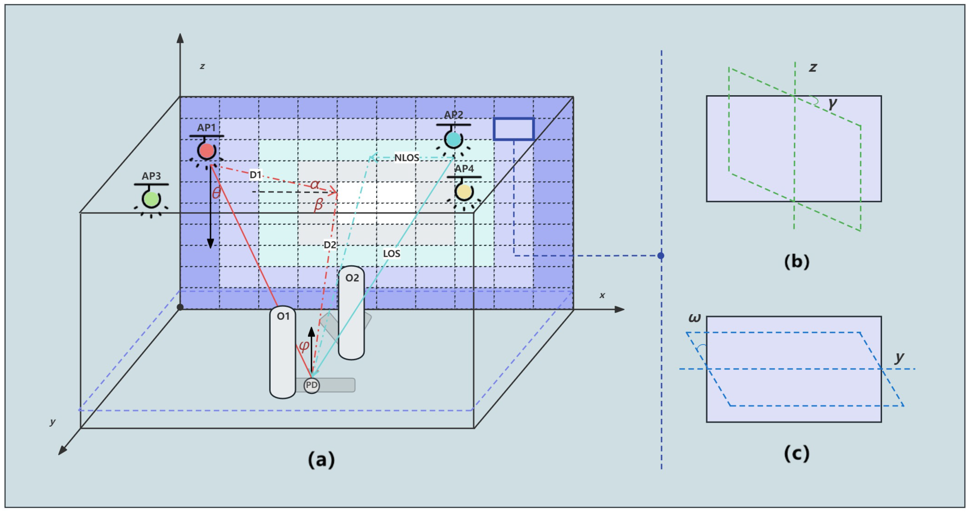
An indoor multi-AP IRS-VLC system is shown in Figure 1, where the APs are positioned on the ceiling, and the receivers are located at the detector plane. Multiple blockers at the detector plane are distributed randomly. An IRS array consisting of passive reflecting elements is deployed on a wall.
In the proposed IRS-aided VLC system, multiple APs and random blockers are considered as the transmitted signal sources and obstacles, represented as A P i and O j , respectively, where i = 1 , 2 , , N and j = 1 , 2 , , M . A comprehensive occlusion indication matrix C A P i represents the occlusion status of A P i , indicating whether the direct LOS path from A P i to the receiver is blocked by any obstacle or not. The total channel gain H total can be calculated as follows (1):
H total = i = 1 N ( C A P i H Los , i + H NLos , i ) .
where H Los , i and H NLos , i represent the i-th AP’s LOS and NLOS channel gains, respectively. The LOS channel gain from the i-th AP to the receiver is given as follows [16]:
H Los , i = ( m + 1 ) A P D 2 π d 2 cos m ( θ ) T ( ψ ) G ( ψ ) cos ( ψ ) , 0 ψ ψ FOV ; 0 , ψ > ψ FOV .
where m is the Lambertian index calculated by m = 1 / log 2 ( cos ( θ 1 / 2 ) ) , θ 1 / 2 denotes the half-intensity radiation angle, A PD is the physical area of the PD, d denotes the distance between the AP and the user, θ is the angle of irradiance, ψ is the angle of incidence, T ( ψ ) and G ( ψ ) are the gains of the optical filter and the non-imaging concentrator, respectively, and ψ FOV is the FOV of the PD. The gain of the concentrator can be expressed as G ( ξ ) = f 2 / sin 2 ψ FOV , 0 ψ ψ FOV , where f is the refractive index.
Each IRS element has two rotational angles denoted as angle γ at axis Z and ω at axis X, as shown in Figure 2. The NLOS channel gain from the i-th AP to the receiver is given as follows [16]:
H NLos , i = ρ wall / IRS ( m + 1 ) A P D 2 π 2 D 1 2 D 2 2 cos m ( θ ) cos ( ψ ) × 0 ψ ψ FOV ; cos ( α ) cos ( β ) T ( ψ ) G ( ψ ) d A k , 0 , ψ > ψ FOV .
where ρ wall / IRS denotes the reflection coefficient of the wall/IRS, D 1 is the distance from the AP to the reflecting point on the wall/IRS, D 2 is the distance from the reflecting point to the receiver, α symbolizes the incident angle to the reflecting point, and β is the irradiant angle from the reflecting point. The reflective surface is divided into K squared surfaces, and d A k represents the reflective area. Notice that only the first-order reflections are considered. When the IRS is configured, the parameters α and β are influenced by γ and ω , according to [17,18]:   
cos ( α ) = x IRS x AP d IRS AP cos ( ω ) sin ( γ ) + y IRS y AP d IRS AP cos ( ω ) cos ( γ ) + z IRS z AP d IRS A P sin ( ω ) ,
cos ( β ) = x PD x IRS d PD RS cos ( ω ) sin ( γ ) + y PD y IRS d PD R S cos ( ω ) cos ( γ ) + z PD z IRS d PD IRS sin ( ω ) .
where x PD , y PD , z PD , x IRS , y IRS , z IRS , and x AP , y AP , z AP are the coordinates of the receiver PD, IRS, and AP, respectively. d IRS AP and d AP IRS denote the distance from the AP to the IRS and the distance from the IRS to the PD, respectively. The EE of wireless communications is defined as the ratio of transferred bits to energy usage [19,20]. In the IRS-VLC system, the transmitters and IRS consume the most power. Each IRS element consumes an amount of energy when it rotates, with negligible differences in rotation angles. Assume that the IRS array is organized as a two-dimensional structure with R rows and C columns, creating an R × C matrix. Each IRS element e r c is uniquely determined by its row and column indices, where r = 1 , 2 , , R and c = 1 , 2 , , C . Therefore, the total power consumption of the IRS-VLC system can be expressed as follows (6):
P t o t a l = P total _ AP + P total _ IRS = i = 1 N P AP , i + N IRS · P IRS , r c ,
where P AP , i is the power consumption of the i-th AP, and P AP i = P t , i + ε + I D C 2 + P hsp . P t , i represents the transmit power of the i-th AP. ε , I D C , and P h s p are the variance of the signal values, the DC-offset, and the hardware static power consumed in each AP, respectively. N IRS is the total number of active IRS elements. The received optical power is expressed asas follows (7):
P r = i = 1 N H total , i P t , i .

3. Problem Formulation and Coalitional Game Theory-Based Resource Allocation

Obstacles can block light, causing interruptions in VLC signals. Modeling occlusion and shadow areas is essential for evaluating the communication performance of the VLC system, particularly when aiming for an optimal system design that includes APs and IRSs. In this section, we begin by formulating the optimization problem and then employ coalitional game theory-based resource allocation to solve it.

3.1. Problem Formulation

We employ a modeling scheme that combines spatial geometry methods with simplified ray tracing, which is suitable for multi-AP and multi-obstacle VLC systems. This approach strikes a balance between accuracy and computational efficiency [21].
The spatial area is split into grids with N rows and M columns. The obstruction status of a single AP is determined by the matrix L A P i , O j , which represents the LOS obstruction status between the ( A P i ) and ( O j ).
L A P i , O j = l 1 , 1 i , j l 1 , M i , j l N , 1 i , j l N , M i , j ,
Here, if l n , m i , j = 1 , this indicates that the path from A P i to O j is obstructed at a specific location ( n , m ) ; if l n , m i , j = 0 , this indicates no obstruction. Then, a comprehensive obstacle indication matrix C A P i for each AP is acquired. C A P i is constructed by performing a logical OR operation on all obstacle indication matrices L A P i , O j , which takes into account the occlusion effects of all obstacles on a specific AP, i.e.,
C A P i = L A P i , O 1 L A P i , O 2 L A P i , O n .
The lower bound of the achievable data rate of the IRS-VLC system can be characterized as follows [22]:
R VLC IRS = B log 2 1 + exp ( 1 ) 2 π × p q R P D i = 1 N C A P i H Los , i + r = 1 R c = 1 C H NLos , i , r c 2 N B
Here, B, p, q, R P D , and N, respectively, denote the system bandwidth, optical transmit power, ratio of transmitted optical power to electrical power, PD’s responsivity, and power spectral density of noise at the PD. Typically, q = 3. H NLos , i , r c represents the channel gain of the NLOS path from the i-th AP through the IRS element located at row r and column c. EE is then defined as follows (11):
E E = R VLC IRS P t o t a l .
The uniformity of the received power can be evaluated using the mean square error (MSE) of the received power:
MSE = E P r E ( P r ) 2 .
Two weighting coefficients, w 1 and w 2 , are introduced to assist in adapting EE to different scenarios. This non-convex problem can be expressed as follows:
max N , P t , i , N IRS , γ r c , ω r c F = w 1 · EE max ( EE ) + w 2 · MSE max ( MSE )
s . t . C 1 : π 2 γ r c π 2 , π 2 ω r c π 2 ,
C 2 : N IRS N IRS MAX ,
C 3 : R VLC IRS R VLC IRS max ,
C 4 : P t o t a l P max ,
C 5 : P t min P t , i P t max , P t , i Z .
Here, C1 and C2 are responsible for maintaining the viability of the IRS array in the IRS-VLC system. C1 adjusts orientation angles, while C2 controls the number of elements, represented by N IRS MAX = R × C , which denotes the maximum operational capacity of the IRS. C3 ensures that the system’s ADR R min maintains quality of service. C4 limits the total power consumption to P max , and C5 restricts each AP’s transmit power to a range between P t min and P t max .
The EE optimization problem in the related IRS-VLC system is non-convex and combinatorial, posing challenges for tractability within polynomial time. To tackle this complexity efficiently, we address LED allocation, IRS rotation, and IRS element selection in succession. The active IRSs can be viewed as a way of partitioning the set of IRS elements. However, verifying all the possible combinations is an arduous task and demands high computational cost, especially as the number of IRS elements increases.

3.2. Coalitional Game Strategy

In the context of a robust IRS-VLC system, we define a coalitional game. In the coalitional game G = ( I , U , S ) with non-transferable utility, the player set I encompasses all IRS elements within the system. The structure of coalitions, S , is denoted by { S 1 , S 2 , , S x , , S X } , with each S x representing a coalition of IRS elements. Distinctiveness among coalitions is maintained, i.e., we need to ensure S a S b = for any a b , and x = 1 X + 1 S x = I . The utility function U ( S x ) is formally defined as follows (14):
U ( S x ) = 0 , if k S x : ( E E i < E E min ) ( P t , i < P t min ) ( P t , i > P t max ) ( R VLC IRS < R min ) ; k S x Φ k , otherwise .
Here, Φ k quantifies the performance contribution of element k, incorporating an EE tailored to the system’s optimization criteria. When considering two coalitions, S x and S y , an IRS element favors moving to a new coalition if it improves the overall system performance, denoted by S y S x . The utility of the system before the transfer is the sum of the utilities of the two coalitions U ( S x ) + U ( S y ) , and the utility of the system after the transfer is the sum of the utilities of the modified coalitions U ( S x { k } ) + U ( S y { k } ) . Thus, the transfer rule is encapsulated as follows (15):
S y S x U ( S x { k } ) + U ( S y { k } ) > U ( S x ) + U ( S y ) C S ( S ) > C S ( S ) ,
where C S ( S ) = x = 1 X + 1 U ( S x ) denotes the sum utility of the current coalition structure S , and
S = ( S { S x , S y } ) { ( S x { k } ) , ( S y { k } ) }
represents the new structure post transfer. According to Equation (15), the system achieves optimal performance when no further beneficial reallocations are possible, resulting in a final structure S final , which represents the solution to the resource allocation challenge.

3.3. Coalition Formation Algorithm

Unit(s): Define the center unit(s), which might be a single element or a collection of neighboring items in an array with odd or even rows and columns. Let ( r 0 , c 0 ) represent the core unit.
Coalition Levels: The k-th coalition S k includes all elements that are at a row–column distance of k from the central unit. This can be defined as follows (17):  
S k = { e r c | max ( | r r 0 | , | c c 0 | ) = k } x = 0 k 1 S x .
For example, the 0-th coalition S 0 only includes the central unit, S 1 includes the ring of elements around the central unit, and subsequently, the k-th coalition S k includes all elements that are at a row–column distance of k from the central unit, excluding those in S 0 , S 1 , , S k 1 . Thus, each coalition is a disjoint set, meaning that there are no shared elements between coalitions. For instance, in a 5 × 5 array, if ( 3 , 3 ) is the center, then S 0 = { e 33 } , S 1 would include the 8 elements surrounding e 33 , S 2 would be the second ring of 16 elements, and so on. In a 4 × 4 array, a single central unit might not exist. In such cases, a group of central units can be selected, such as ( 2 ,   2 ) ,   ( 2 ,   3 ) ,   ( 3 ,   2 ) , and ( 3 ,   3 ) , and then coalitions can be defined at each level based on this selection.
Algorithm 1 Integrated Game-Theoretical Approach for IRS-Assisted VLC Optimization
1:
Input: Parameters θ , m , P total , ρ wall , ρ irs , B , N , R pd .
2:
Initialization and Central Unit Identification:
3:
Define spatial grid N × M and initialize AP i , O j .
4:
Identify central unit ( r 0 , c 0 ) and initialize coalitions S based on geometric proximity.
5:
Channel Modeling with Shadow Assessment:
6:
for each AP i  do
7:
   Calculate H LOS and H NLOS , considering O j .
8:
end for
9:
Sub-problem P 1 : Optimize { P t , i , N } Adjust AP power levels to optimize system coverage and connectivity.
10:
Sub-problem  P 2 : Optimize { γ r c , ω r c } Optimize IRS configurations for minimal shadow impact and maximal H NLOS .
11:
Coalitional Game Strategy: Form game G = ( I , U , S ) using outcomes from P 1 and P 2 .
12:
for each possible coalition transfer do
13:
   Evaluate U ( S x ) for potential improvements.
14:
   if transfer yields higher system utility then
15:
      Execute transfer, updating S .
16:
   end if
17:
end for
18:
Final Configuration and Output:
19:
Determine S final ensuring no further beneficial reallocations.
20:
Output optimized γ , ω , AP i configurations.
During the initial phase of coalition creation in the IRS-VLC system, we establish an efficient method for grouping IRS elements into distinct coalitions based on their geometric positions relative to a central reference point. To begin, we identify the center unit(s) of the IRS array, which serve as the anchors for subsequent coalition levels. Two terms are defined to explain how IRS sections form coalitions.
Coordination among IRS elements is crucial to improve the performance of the VLC system, leveraging the coalition structure and transfer rule. When combined with the channel characteristics of VLC, the process of coalition initialization unfolds as follows. The overall process is illustrated in Algorithm 1.
Step 1. Initialize coalitions
Leveraging this systematic approach, we initialize the coalition structure S for the IRS-VLC system. Each coalition S k is formed to include IRS elements at the same geometric level, ensuring that the initial coalition formation strictly adheres to the spatial layout of the IRS array.
Step 2. Communication channel assessment
To initiate the coalitional game, an LED configuration must be determined first. Thus, we split the optimization problem into two sub-problems, namely P 1 and P 2 . The first sub-problem P 1 focuses on optimizing a set of variables, specifically N , P t , i , while the second sub-problem P 2 deals with optimizing γ r c , ω r c , with the remaining set held constant. The first sub-problem can be expressed as follows (18a):
( P 1 ) : max N , P t , i F
subject to
P t o t a l P m a x ,
P t min P t , i P t max , P t , i Z .
The second sub-problem can be expressed as follows (19a):
( P 2 ) : max γ r c , ω r c F
subject to
π 2 γ r c π 2 , π 2 ω r c π 2 ,
N IRS N IRS MAX .
Step 3. Satisfy the system requirements
In this step, the coalitional game is initiated to identify the configuration that maximizes the EE sum. For each iteration, P 1 and P 2 are found with Algorithm GA and PSO, and it is verified if a user should stay in the previously assigned coalition or if it moves to another one in case (15) is satisfied. Finally, the configuration that maximizes the EE prioritizes IRS elements according to their capacity to meet or exceed the ADR thresholds. This involves reallocating resources to guarantee an optimal system performance.

3.4. Theoretical Analysis

Convergence: The effectiveness of the coalition formation algorithm is highlighted by its inherent convergence properties. These properties guarantee a transition from an initial arbitrary coalition structure, denoted by F i n , to a final optimal coalition structure, F f i n , regardless of the initial configuration.
Proof: The convergence of the proposed algorithm is guaranteed by the finite nature of possible coalition structures within the IRS components. Considering the limited number of IRS components, the total number of feasible coalition structures is bounded. The algorithm is designed to incrementally improve the system’s long-term utility, even permitting temporary detriments to immediate benefits. This is encapsulated by the diminishing probability of suboptimal switch operations, formally expressed as lim t + P c ( L t ) = 0 , when the utility of a new coalition C S ( F ) is less than that of the current coalition C S ( F ) . Such a mechanism ensures that each transition within the coalition structure space inherently contributes to a net improvement in the overall system utility, culminating in the stabilization of the algorithm at an optimal coalition structure.
Stability: We define the final coalition structure achieved by the algorithm as F f i n = { F 1 , F 2 , , F m , , F M + 1 } , which is demonstrated to be Nash-stable. This implies that for any IRS component D n within a coalition F m of the final structure, D n F m F f i n , it holds true that F m F m for all possible F m F f i n and F m F m , indicating that no component has an incentive to move to a different coalition.
Proof: In assuming a position contrary to the claim, if there exists an IRS component D n F m for which a preferable coalition F m exists such that F m F m , leading to a new structure F f i n F f i n , this contradicts the stability of F f i n . Therefore, by contradiction, F f i n must be Nash-stable.
Optimality: The Nash-stable coalition structure, F f i n , is also optimal, aligning with the highest system utility or performance metric under consideration.
Proof: Drawing from the methodology in [23], the evolution of coalition structures toward F f i n is akin to the progression of a Markov chain toward a stationary state. As the number of iterations increases, the Markov chain stabilizes, ensuring that the final, Nash-stable structure F f i n represents the system’s optimal configuration. This convergence to a stationary state, as detailed in [23], shows the optimality of F f i n .

4. Simulation Results

The simulation used a 5 m × 5 m × 3 m room configuration with multiple APs and blockers. The blockers were assumed to be distributed randomly and uniformly, and they were modeled as cylinders with a diameter of 0.30 m and a height of 1.65 m . The receiver plane was held 0.75 m above the ground. The IRS consisted of 20 × 20 elements and the dimension of each mirror was 0.15 m × 0.25 m . The total LED power consumption was limited to 20 watts, and each LED was permitted to use no more than 5 watts. The power value must be an integer. The other simulation parameters are summarized in Table 1.
We set a 0.5 m spacing between the obstacle distribution area and the four walls to account for shadow casting. Each resource allocation strategy was evaluated using three sets of optimization objective weights. The first set of weights (Case 1: EE 0.9 /MSE 0.1 ) maximizes data transmission efficiency, the second set (Case 2: EE 0.1 /MSE 0.9 ) emphasizes signal uniformity, and the third set (Case 3: EE 0.5 /MSE 0.5 ) strikes a balance between the two.
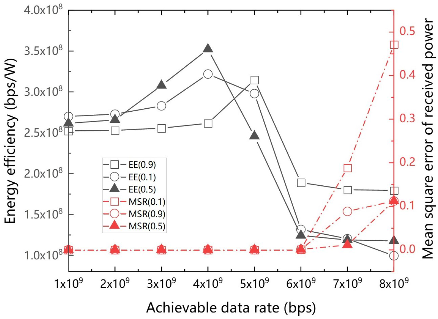
Figure 3 illustrates how the proposed resource allocation strategy impacts the IRS-VLC EE and power MSE under ADR limitations. The results show that EE generally increases with the ADR up to a specific threshold. This increase occurs because the allocated resources are sufficient to meet the corresponding ADR requirements. Therefore, with the same resource consumption, the higher the ADR, the higher the EE. Beyond this threshold, the EE starts to decline, indicating that the system cannot sustain the EE under increased data demands. Case 1 peaks at 5 × 10 9 bps, while Case 2 and Case 3 reach their EE peak at 4 × 10 9 bps. The observed lower EE for Case 3 at higher ADRs is due to the inherent challenges and trade-offs in balancing both the EE and MSR. At higher achievable data rates, this balancing act becomes more challenging, as the system must compensate by driving more IRS components and dynamically adjusting LED power allocations. These results indicate that the proposed strategy can meet diverse data transmission rate requirements, particularly considering the total energy consumption limits of the VLC system. The distinct peaks for each case illustrate the strategy’s adaptability, with Case 3 demonstrating a moderated approach that balances efficiency and signal quality due to its equitable weighting.
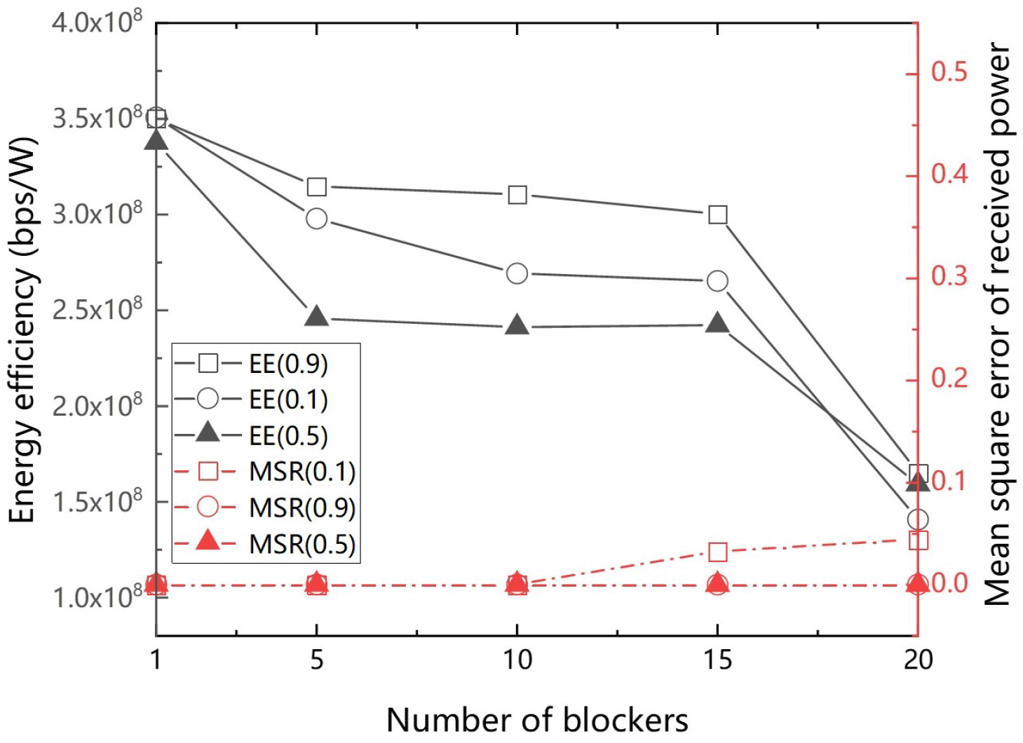
Figure 4 illustrates the impact of the numbers of blockers on the IRS-VLC system’s EE and power MSE. All cases demonstrate that having fewer blockers leads to a higher EE and similar signal quality, whereas having more blockers results in a lower EE. This evidence suggests that solutions can mitigate the impact of blockers, but their effectiveness diminishes as environmental complexity increases.
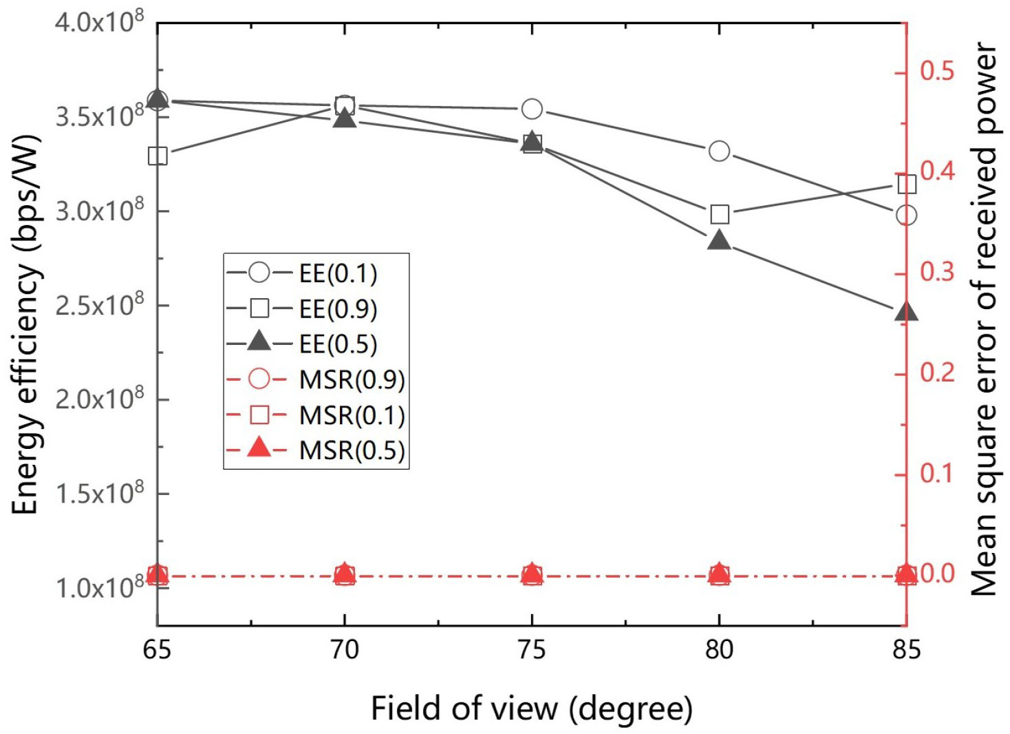
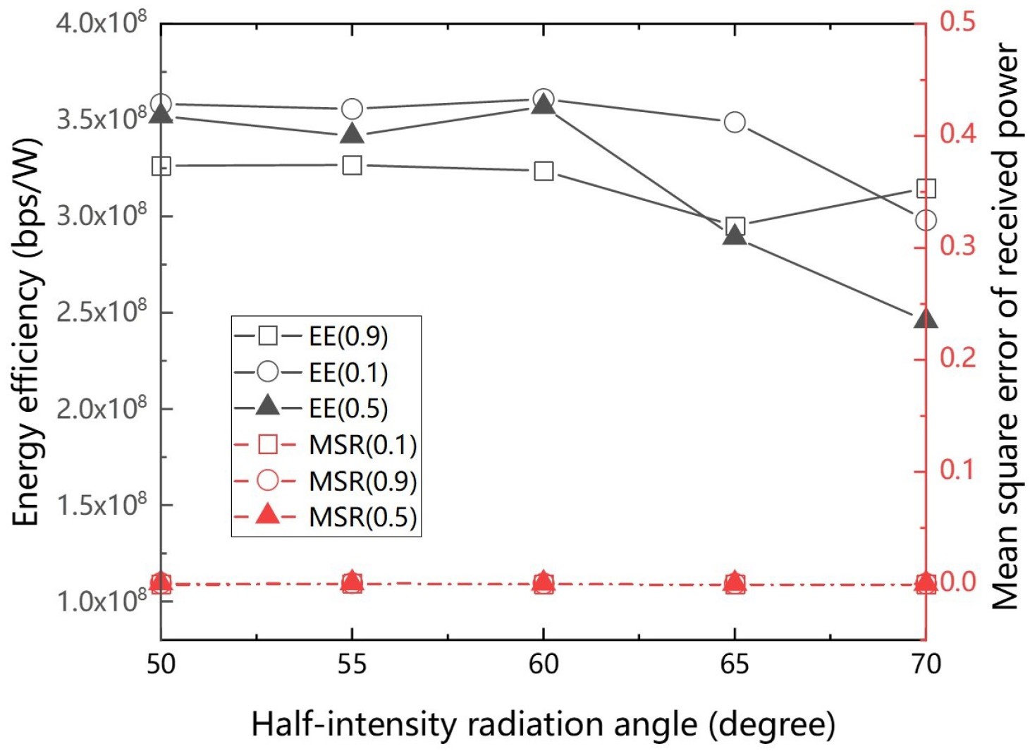
Figure 5 and Figure 6 show the IRS-VLC system performance with varying FOVs and half-intensity radiation angles. The FOV and half-intensity radiation angle synergistically determine the receiver’s light detection and spread. In the half-intensity radiation angle scenario, the important turning point between 60° and 65° matches the 75° FOV turnaround point, where the EE declines. When the angle ranges of the half-intensity radiation angle and the FOV are not optimally matched, the alignment efficiency of the transceiver diminishes, leading to a reduced system performance. Analysis indicates that a system configuration where the FOV and the half-intensity radiation angle complement each other may be optimal. Specifically, a wider FOV can compensate for a narrower radiation angle, and vice versa. This integrated design strategy enables precise performance adjustments for various scenarios, catering to the diverse requirements of different users.
The proposed strategy was evaluated against a baseline optimization method that optimizes IRS elements without configuring LEDs. Figure 7 shows that the proposed strategy enhances the EE by 12.8% in Case 1, 8.3% in Case 2, and 19.3% in Case 3. Since the baseline scheme only optimizes the configuration of IRS elements, it has limited control over the overall system EE and shows a lower performance compared to the game theory-based strategy before reaching the peak. Both the proposed strategy and baseline scheme have similar power MSE values. When the ADR reaches a high value, the proposed strategy outperforms the baseline method in Case 1, demonstrating the robustness of the proposed strategy in signal quality. While the baseline method and the proposed strategy perform equally well in Case 3 for specific low-demand scenarios, this does not detract from the overall superior performance of the proposed strategy. The proposed strategy consistently delivers better results in optimizing the trade-offs between EE and signal quality. This shows that the game-theory-based resource allocation technique is more flexible and efficient than the baseline method, especially when considering trade-offs between EE and received power estimation.

5. Conclusions

This study investigated a coalitional game theory-based resource allocation strategy for IRS-VLC systems to improve the EE and communication performance. Simulation analyses were performed to evaluate the strategy to optimize the EE under various operational scenarios. Three scenarios were analyzed with different weightings, and the proposed strategy shows significant improvements in EE. The scenario prioritizing EE achieved a 12.8% enhancement, while the scenario focusing on power MSE achieved an 8.3% increase. The scenario balancing the EE and power MSE showed an impressive 19.3% gain. The proposed strategy demonstrates strong robustness and flexibility within a certain range of obstacles.

Author Contributions

C.L. and L.F. wrote the main manuscript text, and all authors reviewed the manuscript. All authors have read and agreed to the published version of the manuscript.

Funding

This research was funded by the Interdisciplinary Research Project for Young Teachers of USTB (Fundamental Research Funds for the Central Universities), grant number FRF-IDRY-21-019.

Institutional Review Board Statement

Not applicable.

Informed Consent Statement

Not applicable.

Data Availability Statement

No new data were created.

Conflicts of Interest

The authors declare no conflicts of interest.

References

  1. Saad, W.; Bennis, M.; Chen, M. A vision of 6G wireless systems: Applications, trends, technologies, and open research problems. IEEE Netw. 2019, 34, 134–142. [Google Scholar] [CrossRef]
  2. Sun, S.; Yang, F.; Song, J.; Han, Z. Joint resource management for intelligent reflecting surface–aided visible light communications. IEEE Trans. Wirel. Commun. 2022, 21, 6508–6522. [Google Scholar] [CrossRef]
  3. Yang, Z.; Chen, M.; Saad, W.; Xu, W.; Shikh-Bahaei, M.; Poor, H.V.; Cui, S. Energy-efficient wireless communications with distributed reconfigurable intelligent surfaces. IEEE Trans. Wirel. Commun. 2021, 21, 665–679. [Google Scholar] [CrossRef]
  4. Pan, C.; Zhou, G.; Zhi, K.; Hong, S.; Wu, T.; Pan, Y.; Ren, H.; Di Renzo, M.; Swindlehurst, A.L.; Zhang, R.; et al. An overview of signal processing techniques for RIS/IRS-aided wireless systems. IEEE J. Sel. Top. Signal Process. 2022, 16, 883–917. [Google Scholar] [CrossRef]
  5. Hail, C.U.; Michel, A.K.U.; Poulikakos, D.; Eghlidi, H. Optical metasurfaces: Evolving from passive to adaptive. Adv. Opt. Mater. 2019, 7, 1801786. [Google Scholar] [CrossRef]
  6. Zhang, X.G.; Sun, Y.L.; Zhu, B.; Jiang, W.X.; Yu, Q.; Tian, H.W.; Qiu, C.W.; Zhang, Z.; Cui, T.J. A metasurface-based light-to-microwave transmitter for hybrid wireless communications. Light Sci. Appl. 2022, 11, 126. [Google Scholar] [CrossRef] [PubMed]
  7. Zhao, L.; Wang, Z.; Wang, X. Wireless power transfer empowered by reconfigurable intelligent surfaces. IEEE Syst. J. 2020, 15, 2121–2124. [Google Scholar] [CrossRef]
  8. Guo, H.; Liang, Y.C.; Chen, J.; Larsson, E.G. Weighted sum-rate maximization for reconfigurable intelligent surface aided wireless networks. IEEE Trans. Wirel. Commun. 2020, 19, 3064–3076. [Google Scholar] [CrossRef]
  9. Huang, C.; Zappone, A.; Alexandropoulos, G.C.; Debbah, M.; Yuen, C. Reconfigurable intelligent surfaces for energy efficiency in wireless communication. IEEE Trans. Wirel. Commun. 2019, 18, 4157–4170. [Google Scholar] [CrossRef]
  10. Abdelhady, A.M.; Salem, A.K.S.; Amin, O.; Shihada, B.; Alouini, M.S. Visible light communications via intelligent reflecting surfaces: Metasurfaces vs mirror arrays. IEEE Open J. Commun. Soc. 2020, 2, 1–20. [Google Scholar] [CrossRef]
  11. Tan, X.; Sun, Z.; Jornet, J.M.; Pados, D. Increasing indoor spectrum sharing capacity using smart reflect-array. In Proceedings of the 2016 IEEE International Conference on Communications (ICC), Kuala Lumpur, Malaysia, 22–27 May 2016; pp. 1–6. [Google Scholar]
  12. Ndjiongue, A.R.; Ngatched, T.M.; Dobre, O.A.; Haas, H. Toward the use of re-configurable intelligent surfaces in VLC systems: Beam steering. IEEE Wirel. Commun. 2021, 28, 156–162. [Google Scholar] [CrossRef]
  13. Abumarshoud, H.; Selim, B.; Tatipamula, M.; Haas, H. Intelligent reflecting surfaces for enhanced NOMA-based visible light communications. In Proceedings of the ICC 2022-IEEE International Conference on Communications, Seoul, Republic of Korea, 16–20 May 2022; pp. 571–576. [Google Scholar]
  14. Xu, B.; Huang, H.; Wang, J.B.; Qiu, L.; Zhang, H.; Zhang, Y. Energy-Efficient Precoding Design for Downlink IRS-Assisted URLLC System. In Proceedings of the 2022 IEEE 2nd International Conference on Information Communication and Software Engineering (ICICSE), Chongqing, China, 18–20 March 2022; pp. 141–145. [Google Scholar]
  15. Li, Y.; Jin, D.; Yuan, J.; Han, Z. Coalitional games for resource allocation in the device-to-device uplink underlaying cellular networks. IEEE Trans. Wirel. Commun. 2014, 13, 3965–3977. [Google Scholar] [CrossRef]
  16. Komine, T.; Nakagawa, M. Fundamental analysis for visible-light communication system using LED lights. IEEE Trans. Consum. Electron. 2004, 50, 100–107. [Google Scholar] [CrossRef]
  17. Aboagye, S.; Ngatched, T.M.; Dobre, O.A.; Ndjiongue, A.R. Intelligent reflecting surface-aided indoor visible light communication systems. IEEE Commun. Lett. 2021, 25, 3913–3917. [Google Scholar] [CrossRef]
  18. Yang, T.; Wang, P.; Li, G.; Wang, H.; Li, S.; Shi, H.; He, H.; Shi, F.; Chi, S. Average signal-to-noise ratio maximization for an intelligent reflecting surface and angle diversity receiver jointly assisted indoor visible light communication system. Appl. Opt. 2022, 61, 10390–10399. [Google Scholar] [CrossRef] [PubMed]
  19. Basar, E. Reconfigurable intelligent surface-based index modulation: A new beyond MIMO paradigm for 6G. IEEE Trans. Commun. 2020, 68, 3187–3196. [Google Scholar] [CrossRef]
  20. Björnson, E.; Özdogan, Ö.; Larsson, E.G. Intelligent reflecting surface versus decode-and-forward: How large surfaces are needed to beat relaying? IEEE Wirel. Commun. Lett. 2019, 9, 244–248. [Google Scholar] [CrossRef]
  21. Liu, C.; Wang, J.; Feng, L.; Chen, H.; Xue, Z. Robust layout optimization for intelligent reflecting surfaces-based visible light communication systems. Appl. Opt. 2024, 63, 2020–2029. [Google Scholar] [CrossRef] [PubMed]
  22. Wang, J.B.; Hu, Q.S.; Wang, J.; Chen, M.; Wang, J.Y. Tight bounds on channel capacity for dimmable visible light communications. J. Light. Technol. 2013, 31, 3771–3779. [Google Scholar] [CrossRef]
  23. Mi, Y.; Song, Q. Energy efficiency maximization for IRS-aided WPCNs. IEEE Wirel. Commun. Lett. 2021, 10, 2304–2308. [Google Scholar] [CrossRef]
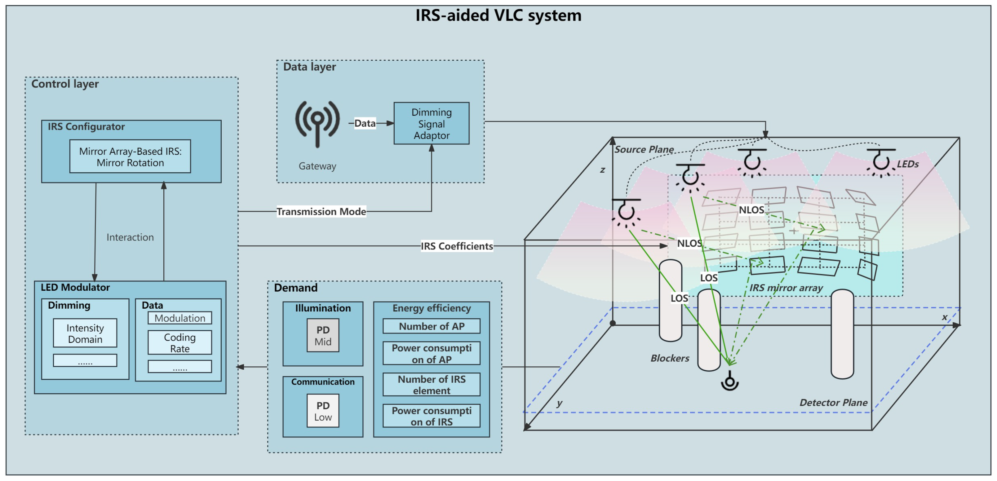
Figure 1. Multiple-AP IRS-VLC system model with random blockers.
Photonics 11 00582 g001
Figure 2. IRS configuration in VLC system. (a) System environment. (b) Yaw angle γ in axis Z of IRS element. (c) Roll angle ω in axis X of IRS element.
Photonics 11 00582 g002
Figure 3. System EE and power MSE under different ADR constraints.
Photonics 11 00582 g003
Figure 4. System EE and power MSE under varying numbers of blockers.
Photonics 11 00582 g004
Figure 5. System EE and power MSE under different FOVs.
Photonics 11 00582 g005
Figure 6. System EE and power MSE under different half-intensity radiation angles.
Photonics 11 00582 g006
Figure 7. Comparison of EE and power MSE between proposed game theory-based resource allocation strategy and baseline algorithm under different weights. (a) EE0.9/MSE0.1 (b) EE0.1/MSE0.9 (c) EE0.5/MSE0.5.
Photonics 11 00582 g007
Table 1. Main parameters.
ParameterValue
Scene size (length × width × height)5 × 5 × 3 m 3
IRS element size (length × height) 0.15  ×  0.25   m 2
FOV 85
θ 1 / 2 70
PD responsivity0.53 A/W
Power spectral density of noise 10 21 A 2 /Hz
Optical filter gain1
Lens index of refraction1.5
ρ wall 0.8
ρ IRS 0.95
System bandwidth200 MHz
Disclaimer/Publisher’s Note: The statements, opinions and data contained in all publications are solely those of the individual author(s) and contributor(s) and not of MDPI and/or the editor(s). MDPI and/or the editor(s) disclaim responsibility for any injury to people or property resulting from any ideas, methods, instructions or products referred to in the content.