Abstract
Atmospheric turbulence causes transmitted light to fade randomly, which results in irradiance scintillation fluctuations in the received signal and significantly affects the quality of wireless optical communication systems. In this paper, we investigate the propagation characteristics of a monochromatic light-emitting diode (LED) light beam through weak-to-strong turbulence. Considering the spatial incoherence of a monochromatic LED light source, the emitted light field of a monochromatic LED light source is represented by a random field multiplied by a deterministic field that follows a Gaussian distribution. Then, based on the extended-Rytov theory, a closed expression for the irradiance scintillation index under weak-to-strong turbulence is derived. In addition, the expression for the fading probability governed by the Gamma–Gamma model is given. Finally, the effects of near-earth atmospheric refractive index structural parameters, signal propagation distances, and working light wavelengths on propagation characteristics of the LED-based VLC system are simulated and compared with those of the laser-based one. The results theoretically confirm that laser light sources are more susceptible to atmospheric turbulence along the propagation path than monochromatic LED light sources. The investigation in this paper can provide theoretical support for the design of visible light communication systems in practical applications.
1. Introduction
Visible light communication (VLC) systems can be generally classified into laser-based VLCs and light-emitting diode (LED)-based VLCs. Compared with a laser source, an LED light source has the advantages of low power consumption, low cost, and combines both lighting and communication characteristics [1,2,3]. Moreover, LED light sources emit incoherent, random-phase beams. This property results in a more diffused energy distribution compared to a laser beam, which is highly coherent and focused, so there is no need to solve the precise tracking and aiming issues in an LED-based VLC system. However, signal attenuation over the distance of an LED-based VLC system is more serious than that of a laser-based VLC system due to the characteristics of a large radiation angle, poor directionality, and insufficient concentration of the LED source. Owing to the relatively low brightness and high signal attenuation, LED-based VLC systems are more suitable for short-range communication scenarios [2,3,4].
Over the recent decade, a series of studies have been conducted on LED-based VLC systems. In 2004, researchers published a paper in IEEE Transactions on Consumer Electronics, which theoretically confirmed the feasibility of using LEDs for indoor visible light communication [5]. In 2014, researcher Yamazato T [6] introduced an outdoor VLC system using LED arrays and image sensors (IS) as optical transceivers. In 2019, Fudan University and Huawei conducted a joint study in which a free-space LED-based VLC system achieved a transmission rate of up to 5 Gb/s over a distance of 1.7 m [7]. In 2019, Tsinghua University carried out a theoretical study on the modeling of the ultraviolet (UV) LED optical communication channel and performed experimental verifications [8]. In 2021, Eso E and his colleagues compared the link performance of a camera and a photodiode as optical receivers in a vehicular LED-based VLC system under atmospheric turbulence conditions [9]. More recently, in 2024, researcher Nguyen QD and his colleagues implemented a system to decode the data transmitted from LEDs in a VLC system, which supports indoor positioning applications [10]. In addition, a series of studies have been carried out in the fields of underwater LED communication, monochrome LED traffic light networking communication, LED-based visible light positioning, and key components and modulation methods of LED optical communications [11,12,13,14,15].
However, VLC has the problem of being greatly affected by objective environments. Absorption and scattering of the transmitted light beam caused by atmospheric aerosols can lead to signal attenuation. Besides signal attenuation, random fluctuations in the optical refractive index caused by atmospheric turbulence disturbances can also lead to channel fading such as beam expansion, beam drift, and irradiance scintillation at the receiver. Among them, irradiance scintillation has the most serious impact on signal reception. Although there have been many studies on the propagation characteristics of LED-based VLC systems affected by atmospheric turbulence, few studies have considered the effects of the random phase of incoherent light sources, and the channel propagation characteristics of LED-based VLC affected by atmospheric turbulence are mainly approximated by the propagation theory of coherent light [16,17,18,19,20]. Since coherent light has a single frequency and a fixed phase difference, while incoherent light has a random phase, studying the propagation characteristics of incoherent light in weak-to-strong turbulence in VLC systems is challenging.
In this work, we investigate the propagation characteristics of monochromatic LED-based VLC systems in weak-to-strong turbulence and compare the irradiance scintillation index and fading probability of monochromatic LED-based and laser-based VLC systems. Considering the spatial incoherence of the monochromatic LED light source, the emitted light field of a monochromatic LED light source is denoted by a random field multiplied by a deterministic field which obeys a Gaussian distribution. Based on the Rytov theory, the irradiance scintillation index of a monochromatic LED-based VLC system under weak turbulence is derived. Then, considering the loss of spatial coherence caused by the increase in transmission distances, the extended Rytov theory proposed by Andrews is used. Based on the extended Rytov theory, the expression for the irradiance scintillation index of a spatially incoherent monochromatic LED light source under weak-to-strong turbulence conditions is derived. In weak-to-strong turbulence, the intensity statistics of light waves are governed by the Gamma–Gamma model. Based on the Gamma–Gamma model, the expression for the fading probability is given. Finally, a series of numerical simulations under various conditions are carried out and discussed based on these expressions. The results theoretically confirm that laser light sources are more susceptible to atmospheric turbulence along the propagation path than monochromatic LED light sources in weak-to-strong turbulence. The research in this paper is of great significance to optical communications and provides theoretical support for the design of VLC systems in practical applications.
2. Propagation of Monochromatic LED Beams with Spatially Incoherent Property in Weak-to-Strong Turbulence
This section describes the behavior of a monochromatic LED-based VLC system in the horizontal direction under weak-to-strong turbulence. As shown in Figure 1, at the transmitter, an electrical signal that is encoded and modulated is loaded onto the LED. The monochromatic LED light source emits a spatially incoherent but monochromatic light beam into the atmospheric channel. The propagating beam experiences a turbulent atmosphere before it reaches the receiving end. At the receiver, the photodetector converts the detected light signal into an electrical signal and then outputs it.
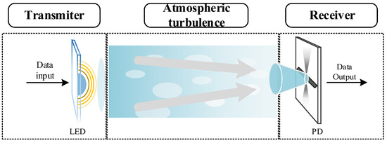
Figure 1.
Monochromatic LED-based VLC system through turbulent atmosphere.
2.1. Irradiance Scintillation Index in Weak Turbulence
Monochromatic LED light sources emit single-frequency but spatially incoherent, random phase beams. Taking into account the spatial incoherence of monochromatic LED light sources, the emitted light field of the LED source is represented by a random field multiplied by a deterministic field , which can be written as , and is the transverse source coordinate. Parameter presents the random phase of the random field . The deterministic field can be expressed in Gaussian form with unit amplitude [4], where is the Gaussian beam width. According to the extended Huygens–Fresnel principle, the form of the incident light field of the propagation beam through atmospheric turbulence at the receiver is as follows [4]:
where and are the propagation link distance and wave number, respectively. is the wavelength. denotes the random complex phase, where is the log amplitude and represents phase fluctuations.
The average light intensity is known as , where and denote the complex conjugate and the ensemble average over the medium statistics, respectively. Using Equation (1), the average light intensity can be written in the following form:
The second-order source mutual coherence function at the receiver can be expressed as follows [21]:
where and are two position vectors in the receiving plane. Under atmospheric turbulence, the second-order statistics of the complex phase perturbation is given by [4], and is the coherence length of the transmission beam. Substituting these into Equation (2), the average intensity is reduced to
By the same token, the ensemble average of the square of the instantaneous light intensity is
The Kolmogorov spectrum model is used to describe the power spectrum for homogeneous and isotropic atmospheric turbulence, where and are the atmospheric refractive index structural parameter and spatial frequency, respectively. By inserting and Equation (3) and integrating over and , Equation (5) can be reduced as follows:
For the log amplitude obeying the Gaussian distribution, the approximation [22] can be employed, where is the variance of the log amplitude fluctuations for the optical wave. After integrating over and , Equation (6) is reduced to
The irradiance scintillation index is defined as . Substitute Equations (4) and (7) into this definition. The irradiance scintillation index for the monochromatic LED-based VLC under weak turbulence becomes
For such an aggregated beam with a Gaussian distribution, as the beam propagation distance increases, the beam exhibits the characteristics of a spherical wave due to fluctuation spreading. Therefore, under weak turbulence conditions, the equation is employed, where is the Rytov variance for a spherical wave [4]. Therefore, the irradiance scintillation index of a LED source for a spherical wave in weak turbulence can be expressed as follows:
2.2. Irradiance Scintillation Index in Weak-to-Strong Turbulence
The conventional Rytov theory is used to solve the Helmholtz equation in order to obtain the expression for the light field under weak turbulence. It is limited to weak fluctuation conditions because it does not consider the effects of the decrease in the transverse spatial coherence radius of the propagating wave. The conventional Rytov theory is not suitable for studying the propagation characteristics of light beams under strong turbulence. Considering the loss of spatial coherence of the optical wave in strong fluctuations caused by the increase in transmission distance, a modification of the Rytov method called the extended Rytov theory was proposed [4]. The extended Rytov theory is a relatively simple model for scintillation fluctuations, which is suitable for moderate to strong fluctuation states. The extended Rytov theory assumes that the received light irradiance is an indicator of the modulation process in which the small-scale field fluctuations are multiplicatively modulated by the large-scale field fluctuations.
Assuming that atmospheric turbulence is homogeneous and isotropic, where inner- and outer-scale effects can be neglected, large-scale and small-scale log-irradiance scintillations are defined by [4]
where and are the large-scale and small-scale filter functions, respectively [4]. Cutoff spatial frequencies and are used to filter out turbulent eddies with scales between and . For calculating large-scale and small-scale log-irradiance scintillations, the following geometrical optics approximation can be used:
By substituting filter functions, the Kolmogorov spectrum, and Equation (11), Equation (10) becomes [4]
where is the Rytov variance in weak turbulence. and are the dimensionless large-scale and dimensionless small-scale cutoff spatial frequencies, respectively [4]:
Inserting Rytov variance for spherical wave , Equation (12) becomes
According to Equation (14), the total scintillation index of a laser light for a spherical wave in weak-to-strong turbulence takes the following form [4]:
For the case in which inner-scale and outer-scale effects can be ignored, by substituting Equation (9), the irradiance scintillation index of a LED source for a spherical wave in weak-to-strong turbulence can be expressed as follows:
The coherence length of the transmission beam for a spherical wave is [4], where is the atmospheric refractive index structural parameter. The Hufnagel–Valley model [23,24,25] is often used to describe the trends in the atmospheric refractive index:
where is velocity and is the near-ground atmospheric refractive index structural parameter.
Figure 2 shows the trends of atmospheric refractive index structural parameters with altitude at different . The values of the atmospheric refractive index structure parameters reflect the intensity of the atmospheric turbulence disturbance to a certain extent. We notice that the atmospheric refractive index structural parameter decreases with increasing altitude. This is because as the altitude increases, the air becomes thinner. As a result, the values of atmospheric refractive index structural parameter show a decreasing trend and gradually stabilize with the increasing altitude.
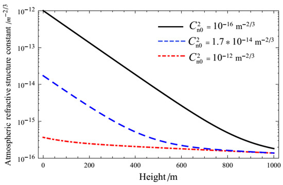
Figure 2.
Trends of atmospheric refractive index structural parameters with altitude.
2.3. Fading Probability
In weak turbulence, the normalized irradiance is governed by a log-normal distribution [4]. However, under strong turbulence conditions, a K-distribution [26] is used instead. In order to characterize the irradiance distribution from weak-to-strong turbulence in terms of a probability distribution function, a Gamma–Gamma distribution is applied [27,28]:
where and are the modified Bessel function of the second kind and the gamma function, respectively. Gamma–Gamma distribution parameters and are related to large-scale and small-scale log-irradiance scintillations:
Define the probability of falling below the fading threshold as the signal fading probability . The probability of fade obeying the Gamma–Gamma distribution can be written in a closed form, as follows:
where is the fading threshold in dB .
3. Numerical Results and Discussions
In this section, the irradiance scintillation index and the signal fading probability of the monochromatic LED light beam propagation through weak-to-strong turbulence are numerically simulated and analyzed. The effects of near-earth atmospheric refractive index structural parameters, signal propagation distances, and working light wavelengths on the irradiance scintillation index and fading probability of the monochromatic LED-based VLC system are compared with those of the laser-based one. Table 1 summarizes the parameters used in the following analysis. The black circles in the figures bellow distinguish the curves between monochromatic LED-based VLC systems and laser-based VLC systems.

Table 1.
System parameters.
Figure 3 illustrates the trends of the irradiance scintillation index with respect to the near-ground atmospheric refractive index structural parameters for different wavelengths and propagation distances. Figure 3a shows the irradiance scintillation index of the monochromatic LED-based VLC system with the propagation distance L = 500 m, while the black, blue, and red colors indicate the wavelengths of 380, 580, and 780 nm, respectively. Figure 3b shows the irradiance scintillation index for the monochromatic LED-based VLC system with the wavelength nm, while the black, blue, and red colors depict the propagation distances of 500, 300, and 200 m, respectively.
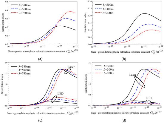
Figure 3.
Trends of scintillation index with near-ground atmospheric refractive index structural parameters. (a,c) L = 500 m; (b,d) nm.
As can be seen from Figure 3a,b, with the increase in the intensity of atmospheric turbulent disturbances, the scintillations index of monochromatic LED light beam increases rapidly, reaches the peak, and then decreases gradually. Figure 3a shows that at a propagation distance of 500 m, as the atmospheric turbulence intensity increases, the scintillation index of a monochromatic LED light source operating at 380 nm is the first to reach the peak, followed by 580 nm, with 780 nm being the slowest. Under weak turbulence (), the scintillation index of the monochromatic LED signal with a working wavelength of 380 nm is the largest among three working wavelengths of 380, 580, and 780 nm. Although increasing wavelength still helps to reduce irradiance scintillation fluctuations, the effect of turbulence on the transmitted beam becomes more significant as the intensity of turbulence increases. Therefore, when atmospheric turbulence intensity increases to moderate-to-strong turbulence, the scintillation fluctuations of the light source at 780 nm are more intense. As shown in Figure 3b, the scintillation index with a propagation distance of 500 m reaches the peak first at a wavelength of 380 nm, and at the same atmospheric turbulence intensity, the farther the signal travels, the greater the scintillation index.
Figure 3c,d compares the scintillation index of laser-based VLC and monochromatic LED-based VLC systems under the same conditions as Figure 3a,b, respectively. As shown in Figure 3c, for a laser-based VLC system, the scintillation index of the optical signal with the shortest operating wavelength nm reaches the peak first, the same as the monochromatic LED-based VLC. Figure 3d indicates that, for different propagation distances (200 m, 300 m, 500 m), the scintillation index of a laser source peaks first at a propagation distance of 500 m. In addition, at the same atmospheric turbulence intensity, the scintillation index of the monochromatic LED light source is lower than that of the laser light source. This suggests that monochromatic LED light beams are less affected by atmospheric turbulence than laser light beams under the same conditions. When the turbulence fluctuations change from weak turbulence to strong turbulence, the scintillation index of the laser-based VLC is significantly higher than that of the monochromatic LED-based VLC. This is because laser light sources have a higher degree of coherence and emit light in a narrower beam with a smaller divergence angle, making them more susceptible to atmospheric turbulence. A turbulent atmosphere makes the scattering and refractive effects of the transmitted laser beam stronger, resulting in significant distortions and spreading of the beam, which in turn leads to a loss in signal quality or intensity. In contrast, monochromatic LED light sources are less coherent and generally have a wider divergence angle than lasers, which means that their light is less concentrated and spread over a larger area. This makes monochromatic LED less susceptible to atmospheric turbulence, resulting in smaller fluctuations in the light signal intensity and a lower irradiance scintillation index. Therefore, in some specific real-time short-range communication scenarios, LED-based VLC systems can provide high-quality communications at a low cost, such as V2V and V2I communications. LED-based VLC systems have the potential to revolutionize the way that vehicles communicate with each other and with infrastructures. LED-based VLC systems can be integrated into vehicle headlights and taillights to transmit information about traffic conditions, road hazards, and other relevant information to nearby vehicles and infrastructure. This information can be used to improve safety and prevent accidents by providing drivers with real-time alerts about potential hazards on the road.
As shown in Figure 3, in weak to moderate turbulence, the scintillation index rises with increasing turbulence intensity. Next, as it increases to strong turbulence, the scintillation index continues to rise and then a peak appears. This is because in this region, the random focusing effect caused by large-scale eddies reaches its maximum. With the increase in the atmospheric turbulence intensity, the focusing effect is weakened by multiple scattering, and thus the scintillation index decreases.
Figure 4 denotes the trends of the irradiance scintillation index with propagation distances for different wavelengths and near-ground atmospheric refractive index structural parameters . Figure 4a,b show the irradiance scintillation index of a monochromatic LED-based VLC system under strong turbulence () and weak turbulence (), respectively. The black, blue, and red colors represent wavelengths of 380, 580, and 780 nm, respectively.
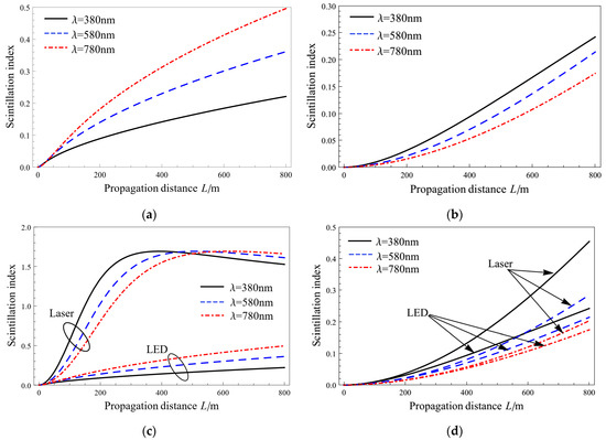
Figure 4.
Trends of scintillation index with propagation distance. (a,c) ; (b,d) .
As shown in Figure 4a,b, the scintillation index of the monochromatic LED light increases gradually as the propagation distance increases. Figure 4a reveals that for a certain signal propagation distance in strong turbulence, the shorter the working light wavelength is, the smaller the scintillation fluctuations of the monochromatic LED-based VLC are. However, under weak turbulence, the situation is totally reversed. It can be seen in Figure 4b that the shorter the working light wavelength, the greater the scintillation index of monochromatic LED-based VLC systems.
Figure 4c,d compares the scintillation index of laser-based VLC and monochromatic LED-based VLC systems under the same conditions as Figure 4a,b, respectively. As can be seen from Figure 4c, the scintillation index of the laser-based VLC system is much higher than that of the monochromatic LED-based one under strong turbulence conditions (). When the beam experiences weak turbulence (), as shown in Figure 4d, the differences between the two VLC systems are not that large. It is worth noting from Figure 3c and Figure 4c that, compared with the monochromatic LED-based VLC system, there is a sharp increase in the scintillation index of the laser-based one in strong turbulence. This indicates that the increase in the atmospheric turbulence intensity has a greater effect on the laser source than the monochromatic LED light source.
Figure 5 denotes the changing trends of fading probability with a fade threshold of , while the black, blue, and red colors represent wavelengths of 380, 580, and 780 nm, respectively, and the propagation distance is 500 m. Figure 5a,b present strong turbulence () and moderate turbulence (), respectively. Since the larger the scintillation fluctuations, the greater the signal fading probability caused by scintillation, for a certain fade threshold in moderate and strong turbulence, the signal fading probability of the laser-based VLC is greater than that of the monochromatic LED-based VLC, as shown in Figure 5.
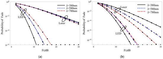
Figure 5.
Trends of fading probability with fade threshold. (a) ; (b) .
The results shown in Figure 3c indicate that the peaks of the scintillation index of the monochromatic LED light source are smaller than that of a laser light source, the monochromatic LED light source peaks under moderate turbulence conditions, and the laser light source peaks in strong turbulence, which means that the monochromatic LED-based VLC system experiences a weaker turbulence intensity at the scintillation peak than the laser-type VLC.
Consequentially, as shown in Figure 5a, under strong turbulence conditions (), the fading probability of the monochromatic LED light source is much lower than that of the laser light source. However, when it experiences moderate turbulence (), as shown in Figure 5b, there is a slight increase in fading probability of the monochromatic LED-based VLC, while that of the laser-based one decreases significantly.
4. Conclusions
In this paper, the expressions of the irradiance scintillation index and fading probability of the monochromatic LED-based VLC system through weak-to-strong turbulence are derived. Then, the effects of near-earth atmospheric refractive index structural parameters, signal propagation distances, and working light wavelengths on irradiance scintillation characteristics of the monochromatic LED source are simulated and compared with those of the laser source. The results show that in contrast to the monochromatic LED light beam, the increase in the intensity of turbulence fluctuations has a greater impact on the laser beam. In particular, the differences of both irradiance scintillation and the probability of fading between the LED and laser beam are especially obvious when the turbulence fluctuations rise from weak turbulence to strong turbulence. This is because the laser beam is more focused and concentrated than the LED light beam, which makes the scattering and refracting effects caused by atmospheric turbulence on the laser beam much stronger. In contrast, monochromatic LED light sources are less coherent and generally have a wider divergence angle than lasers, which means that their light is not as concentrated, resulting in smaller fluctuations in the light signal intensity and a lower irradiance scintillation index. The research in this paper is of great significance to optical communications and provides theoretical support for the design of LED-based VLC systems in practical applications, such as the integration of LED-based VLC systems into vehicle headlights and taillights for V2V and V2I communications or the engineering of smart lighting and communication networks on the Internet of Things.
Author Contributions
Conceptualization, Y.J., W.C. and D.W.; methodology, Y.J., W.C. and D.W.; software, Y.J. and C.C.; validation, C.C. and D.W.; formal analysis, Y.J. and D.W.; resources, Y.J. and C.C.; data curation, Y.J.; writing—original draft preparation, Y.J.; writing—review and editing, W.C. and D.W.; supervision, W.C. and D.W. All authors have read and agreed to the published version of the manuscript.
Funding
This research was funded by the National Key Research and Development Program of China, grant number 2017YFC1500503.
Institutional Review Board Statement
Not applicable.
Informed Consent Statement
Not applicable.
Data Availability Statement
Data are contained within this article.
Conflicts of Interest
The authors declare no conflicts of interest.
References
- Tanaka, Y.; Komine, T.; Haruyama, S.; Nakagawa, M. Indoor visible light data transmission system utilizing white LED lights. IEICE Trans. Commun. 2003, 86, 2440–2454. [Google Scholar]
- Chi, N. LED-Based Visible Light Communications; Springer: Berlin, Germany, 2018. [Google Scholar]
- Shen, C.; Ma, C.; Li, D.; Hu, J.; Li, G.; Zou, P.; Chi, N. High-speed visible laser light communication: Devices, systems and applications. In Broadband Access Communication Technologies XV; SPIE: San Diego, CA, USA, 2021; Volume 11711, pp. 18–27. [Google Scholar]
- Andrews, L.C.; Phillips, R.L. Laser Beam Propagation through Random Media; SPIE Press: Bellingham, WA, USA, 2005. [Google Scholar]
- Komine, T.; Nakagawa, M. Fundamental analysis for visible-light communication system using LED lights. IEEE Trans. Consum. Electron. 2004, 50, 100–107. [Google Scholar] [CrossRef]
- Yamazato, T.; Takai, I.; Okada, H.; Fujii, T.; Yendo, T.; Arai, S.; Kawahito, S. Image-sensor-based visible light communication for automotive applications. IEEE Commun. Mag. 2014, 52, 88–97. [Google Scholar] [CrossRef]
- Shi, M.; Wang, C.; Li, G.; Liu, Y.; Wang, K.; Chi, N. A 5Gb/s 2*2 MIMO Real-Time Visible Light Communication System Based on Silicon Substrate LEDs. In Proceedings of the 2019 Global LIFI Congress (GLC), Paris, France, 12–13 June 2019; pp. 1–5. [Google Scholar]
- Wu, T.; Ma, J.; Yuan, R.; Su, P.; Cheng, J. Single-scatter model for short-range ultraviolet communication in a narrow beam case. IEEE Photonics Technol. Lett. 2019, 31, 265–268. [Google Scholar] [CrossRef]
- Eso, E.; Ghassemlooy, Z.; Zvanovec, S.; Sathian, J.; Abadi, M.M.; Younus, O.I. Performance of vehicular visible light communications under the effects of atmospheric turbulence with aperture averaging. Sensors 2021, 21, 2751. [Google Scholar] [CrossRef] [PubMed]
- Nguyen, Q.D.; Nguyen, N.H. Mobile Application for Visible Light Communication Systems: An Approach for Indoor Positioning. Photonics 2024, 11, 293. [Google Scholar] [CrossRef]
- Shen, T.; Guo, J.; Liang, H.; Li, Y.; Li, K.; Dai, Y.; Ai, Y. Research on a Blue–Green LED Communication System Based on an Underwater Mobile Robot. Photonics 2023, 10, 1238. [Google Scholar] [CrossRef]
- Apolo, J.A.; Ortega, B.; Almenar, V. Hybrid POF/VLC Links Based on a Single LED for Indoor Communications. Photonics 2021, 8, 254. [Google Scholar] [CrossRef]
- Geng, Z.; Khan, F.N.; Guan, X.; Dong, Y. Advances in Visible Light Communication Technologies and Applications. Photonics 2022, 9, 893. [Google Scholar] [CrossRef]
- Yahia, S.; Meraihi, Y.; Ramdane-Cherif, A.; Gabis, A.B.; Acheli, D.; Guan, H. A survey of channel modeling techniques for visible light communications. J. Netw. Comput. Appl. 2021, 194, 103206. [Google Scholar] [CrossRef]
- Álvarez-Roa, C.; Álvarez-Roa, M.; Raddo, T.R.; Jurado-Navas, A.; Castillo-Vázquez, M. Cooperative Terrestrial–Underwater FSO System: Design and Performance Analysis. Photonics 2024, 11, 58. [Google Scholar] [CrossRef]
- Korotkova, O.; Toselli, I. Non-classic atmospheric optical turbulence. Appl. Sci. 2021, 11, 8487. [Google Scholar] [CrossRef]
- Manzoor, H.U.; Manzoor, S.; Manzoor, T.; Khan, T.; Hussain, A. Improved transmission length in the presences of ambient noise and scintillation effect using duobinary modulation in 40 Gbps free space optical channel. Microw. Opt. Technol. Lett. 2020, 62, 3163–3169. [Google Scholar] [CrossRef]
- Ding, H.; Chen, G.; Majumdar, A.K.; Sadler, B.M.; Xu, Z. Turbulence modeling for non-line-of-sight ultraviolet scattering channels. In Atmospheric Propagation VIII; SPIE: Orlando, FL, USA, 2011; Volume 8038. [Google Scholar]
- Jurado-Navas, A.; Raddo, T.R.; Garrido-Balsells, J.M.; Borges, B.H.V.; Olmos, J.J.V.; Monroy, I.T. Hybrid optical CDMA-FSO communications network under spatially correlated gamma-gamma scintillation. Opt. Express 2024, 15, 16799–16814. [Google Scholar] [CrossRef] [PubMed]
- Liao, L.; Li, Z.; Lang, T.; Chen, G. UV LED array based NLOS UV turbulence channel modeling and experimental verification. Opt. Express 2023, 17, 21825–21835. [Google Scholar] [CrossRef] [PubMed]
- Ishimaru, A. Wave Propagation and Scattering in Random Media; Academic Press: New York, NY, USA, 1978. [Google Scholar]
- Fante, R.L. Intensity fluctuations of an optical wave in a turbulent medium effect of source coherence. Opt. Acta Int. J. Opt. 1981, 28, 1203–1207. [Google Scholar] [CrossRef]
- Wu, S.; Hu, X.; Han, Y.; Wu, X.; Su, C.; Luo, T.; Li, X. Measurement and analysis of atmospheric optical turbulence in Lhasa based on thermosonde. J. Atmos. Sol.-Terr. Phys. 2020, 201, 105241. [Google Scholar] [CrossRef]
- Tyson, R.K. Adaptive optics and ground-to-space laser communications. Appl. Opt. 1996, 35, 3640–3646. [Google Scholar] [CrossRef]
- Dirkx, D.; Noomen, R.; Prochazka, I.; Bauer, S.; Vermeersen, L.L.A. Influence of atmospheric turbulence on planetary transceiver laser ranging. Adv. Space Res. 2014, 54, 2349–2370. [Google Scholar] [CrossRef]
- Jakeman, E.; Pusey, P.N. Significance of K distributions in scattering experiments. Phys. Rev. Lett. 1978, 40, 546. [Google Scholar] [CrossRef]
- Yi, X.; Liu, Z.; Yue, P. Optical scintillations and fade statistics for FSO communications through moderate-to-strong non-Kolmogorov turbulence. Opt. Laser Technol. 2013, 47, 199–207. [Google Scholar] [CrossRef]
- Al-Habashm, A.; Andrewsl, C.; Phillipsr, L. Mathematical model for the irradiance probability density function of a laser beam propagating through turbulent media. Opt. Eng. 2001, 40, 1554–1562. [Google Scholar] [CrossRef]
Disclaimer/Publisher’s Note: The statements, opinions and data contained in all publications are solely those of the individual author(s) and contributor(s) and not of MDPI and/or the editor(s). MDPI and/or the editor(s) disclaim responsibility for any injury to people or property resulting from any ideas, methods, instructions or products referred to in the content. |
© 2024 by the authors. Licensee MDPI, Basel, Switzerland. This article is an open access article distributed under the terms and conditions of the Creative Commons Attribution (CC BY) license (https://creativecommons.org/licenses/by/4.0/).