Article

A Terahertz Programmable Digital Metasurface Based on Vanadium Dioxide

1
State Key Laboratory of Millimeter Waves, Nanjing 210096, China
2
School of Integrated Circuits, Southeast University, Nanjing 210096, China
3
School of Information Science and Engineering, Southeast University, Nanjing 210096, China
*
Author to whom correspondence should be addressed.
These authors contributed equally to this work.
Photonics 2024, 11(6), 527; https://doi.org/10.3390/photonics11060527
Submission received: 9 May 2024 / Revised: 28 May 2024 / Accepted: 30 May 2024 / Published: 1 June 2024
(This article belongs to the Special Issue Emerging Trends in Metamaterials and Metasurfaces Research)

Abstract

:
Metasurfaces can realize the flexible manipulation of electromagnetic waves, which have the advantages of a low profile and low loss. In particular, the coding metasurface can flexibly manipulate electromagnetic waves through controllable sequence encoding of the coding units to achieve different functions. In this paper, a three-layer active coding metasurface is designed based on vanadium dioxide ( V O 2 ), which has an excellent phase transition. For the designed unit cell, the top patterned layer is composed of two split square resonant rings (SSRRs), whose gaps are in opposite directions, and each SSRR is composed of gold and V O 2 . When V O 2 changes from the dielectric state to the metal state, the resonant mode changes from microstrip resonance to LC resonance, correspondingly. According to the Pancharatnam-Berry (P-B) phase, the designed metasurface can actively control terahertz circularly polarized waves in the near field. The metasurface can manipulate the order of the generated orbital angular momentum (OAM) beams: when the dielectric V O 2 changes to metal V O 2 , the order l of the OAM beams generated by the metasurface changes from −1 to −2, and the purity of the generated OAM beams is relatively high. It is expected to have important application values in terahertz wireless communication, radar, and other fields.

1. Introduction

Vanadium dioxide ( V O 2 ) is an active kind of metamaterial with excellent phase transition characteristics, which can be switched between the dielectric state and the metal state by temperature control [1,2,3,4,5]. As a special two-dimensional form of metamaterial [6,7,8], a metasurface can realize flexible manipulations of electromagnetic waves [9,10], which has the advantages of a low profile and low loss. Metasurfaces have been extensively studied for quite a long time, and the concept of programmable digital metasurfaces was first put forward in 2014 [11], which are characterized by digitally encoding methods instead of effective media theory (EMT), which subtly links metamaterial physics with digital information [12].
The excellent phase transition characteristics of V O 2 make it suitable for designing active coding metasurfaces. In recent years, various digital coding metasurfaces based on V O 2 have been widely considered, which can realize the functions of orbital angular momentum (OAM) manipulation [13,14,15], beam scanning [16,17], holographic imaging [18], and so on. An active metasurface based on V O 2 was proposed to manipulate the generated OAM beams [19], which works in the Ku band, controlling the linearly polarized waves. The applications of digitally coding metasurfaces in vortex wave communication deserve studying; nevertheless, relevant research works in the terahertz-frequency band are relatively few. For programmable digital metasurface research, the terahertz-frequency band (0.1–10 THz) is one of the areas with great potential [20], representing both microwave and light wave characteristics. On the other hand, the manipulation of circularly polarized waves, which represent significant value in the field of wireless communication, is worth exploring, as well.
In this paper, an active coding metasurface in the terahertz-frequency band is designed based on V O 2 . The top patterned layer of the unit cell consists of two split square resonant rings (SSRRs), whose gaps are in opposite directions, and each SSRR is composed of gold and V O 2 . On account of the excellent phase transition characteristics of V O 2 , the designed metasurface can generate OAM beams and manipulate the order of the OAM beams in the near field, which probably has certain values in terahertz vortex wave communication, photonic integrated circuits [21,22], and other fields.
Compared to other relevant research on active metasurfaces based on V O 2 , the main contributions of this paper can be summarized in three aspects: Firstly, from the perspective of the physical mechanism of the designed metasurface, two different states of V O 2 corresponding to two kinds of resonant modes for the unit cell, this is of great significance for the design of active metasurfaces. Secondly, the design of the active metasurface in this paper is relatively flexible in OAM manipulation for circularly polarized waves, which lacks specific studies in recent years. Lastly, on account of the great potential for vortex wave communication in the terahertz-frequency band, our designed metasurface has potential application values, as well.

2. Design of VO 2 -Based Unit Cell

2.1. Structure of the Designed Unit Cell

The designed unit cell shown in Figure 1 is tunable and consists of three layers; its top and lateral schematic diagrams are represented in Figure 1a and Figure 1b, respectively. The polyimide (the dielectric constant is 3.5) layer is t in thickness and is placed as the middle layer, and the thicknesses of the substrate layer and the top patterned layer are h 1 and h 2 .
The SSRR demonstrates a classical kind of resonance [23]. The top patterned layer is composed of two SSRRs with two gaps, whose widths are d 1 ; the two SSRRs are of the same size, and the gaps are in opposite directions. Each SSRR consists of V O 2 (colored in blue) and gold (colored in yellow). The length of V O 2 in the y-axis direction is m, and the arm of the SSRR is s in width. For the whole patterned layer, the distance is d 2 in the y-axis direction between the bottom of the upper SSRR and the top of the lower SSRR; these two SSRRs occupy a rectangular area, whose width and length are l 1 and l 2 . After careful optimization, the specific values of the above geometric parameters are as follows: P = 90 μ m, t = 20 μ m, h 1 = 0.2 μ m, h 2 = 0.2 μ m, m = 13 μ m, s = 6 μ m, d 1 = 2 μ m, d 2 = 2 μ m, l 1 = 38 μ m, and l 2 = 78 μ m. As shown in Figure 1a, the two SSRRs rotate counterclockwise together around the center of the patterned layer at an angle α .
By controlling the temperature, V O 2 can be switched between the dielectric state and the metal state. The conductivity of the dielectric V O 2 is 200 S/m, where V O 2 represents the metal state. The relative permittivity can be characterized by the Drude model [24,25,26]:
ε ( ω ) = ε + ω p 2 ( σ ) i γ ω ω 2
where σ is the conductivity of V O 2 , ω is the angular frequency of the incident terahertz wave, and ω p ( σ ) is the plasma frequency related to σ . The high-frequency dielectric constant ε = 12 F/m, and the collision frequency γ = 5.75 × 10 13 rad/s, where σ and ω p ( σ ) are both proportional to the density of free carriers. ω p ( σ ) can be approximately expressed as ω p 2 ( σ ) = σ σ 0 ω p 2 ( σ 0 ), σ 0 = 3 × 10 5 S/m, ω p ( σ 0 ) = 1.4 × 10 15 rad/s. The conductivity of V O 2 , which is in the metal state, is set to 2 × 10 5 S/m in this paper [27].
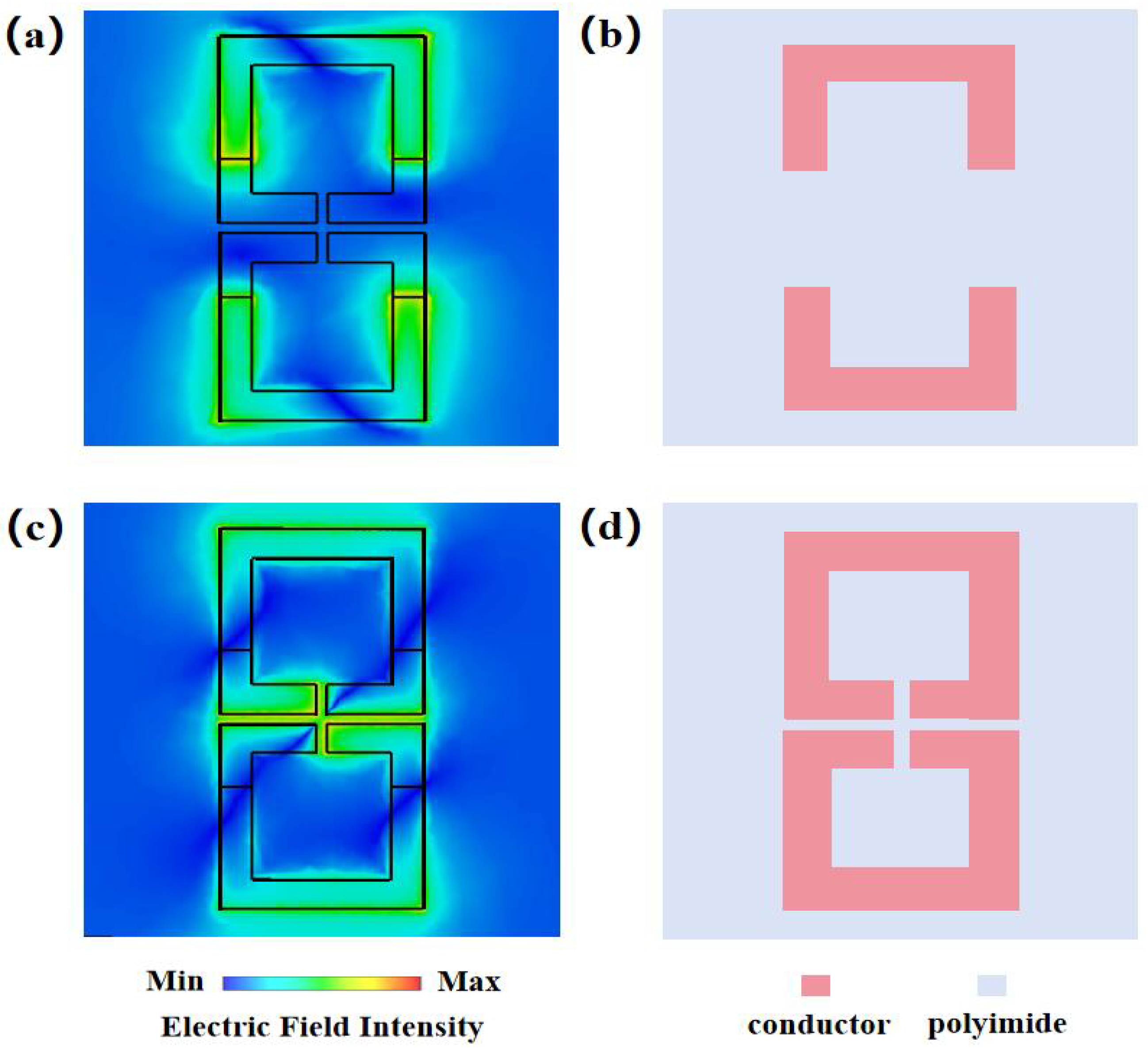
For V O 2 in the dielectric and metal states, the distributions of the electric field intensity in the top patterned layer are represented in Figure 2a,c. V O 2 represents the dielectric state; the electromagnetic properties of the dielectric V O 2 are almost no different from those of general media; in this case, the equivalent structural diagram of the top patterned layer is shown in Figure 2b, which represents the microstrip resonance. When the dielectric V O 2 changes to the metal V O 2 , the resonant mode of the unit cell changes from microstrip resonance to LC resonance [28,29], correspondingly.
Analyzing the condition in which V O 2 is in the metal state, on account of its metal-like electromagnetic properties, the metal V O 2 can be regarded as a conductor. In other words, the top patterned layer can be regarded as two metal SSRRs with two gaps, which are in opposite directions, and the corresponding equivalent structure diagram in this case is shown in Figure 2d. For one of the metal SSRRs, the metal arm (microstrip line) is equivalent to an inductance L; the gap of each SSRR corresponds to a capacitor C 1 , respectively; the part between two SSRRs corresponds to the other capacitor C 2 . When the magnetic field component of the incident terahertz wave passes through one SSRR (or the electric field component stretches over both ends of the gap), the external field energy will be coupled to the SSRR, forming an LC resonant loop [30]. Additionally, the gaps of two SSRRs are relatively small, so that the electromagnetic energy stored in the SSRRs can be exchanged through the local electric field, which is generated by the adjacent metal V O 2 ; thus, the electrically coupled resonance is realized.

2.2. Analyses of Reflection Electromagnetic Response for Unit Cells

In this paper, the Finite-Difference Time-Domain (FDTD) method is used for the periodic simulation of the designed unit cell; the simulation is implemented by using the commercial software CST Microwave Studio. For the convenience of analysis, the subsequently mentioned incident terahertz waves are right-handed circularly polarized (RCP) waves, and the RCP wave is incident on the metasurface in the −z direction. Figure 3a,b show the reflection electromagnetic responses of the unit cell when α takes different values and V O 2 is in the two different states.
According to the theory of the Pancharatnam-Berry (P-B) phase [31,32], by changing the rotation angle α of the whole patterned layer from 0° to 135° at 45-degree steps, four unit cells can be obtained, whose phase covers 0° to 270°, and the phase difference is 45°. The coding units corresponding to the aforementioned adjacent rotation angles can be named as “00”, “01”, “10”, and “11”, respectively. When V O 2 is in the two states and the rotation angle α = 0°, the obtained reflection amplitude and phase diagrams are as shown in Figure 3a,b. The simulation results indicate that, at a frequency f = 1.2 THz, the four unit cells all have high reflectance above 0.8, and the phase difference is approximately 90°, which conforms to the characteristics of the 2-bit coding units. In a similar way, for any two subunits of the aforementioned four units, whose rotation angle α differs by 90°, the phase difference ought to be 180° in theory, thus, the 1-bit coding units can be obtained. In this paper, units with α of 135° and 45° are selected as the 1-bit coding units, and they are called units “0” and “1”, respectively. Generally, for a 1-bit digitally coding metasurface, through controllable sequence encoding of 1-bit coding units, electromagnetic waves can be manipulated and different functions can be realized.
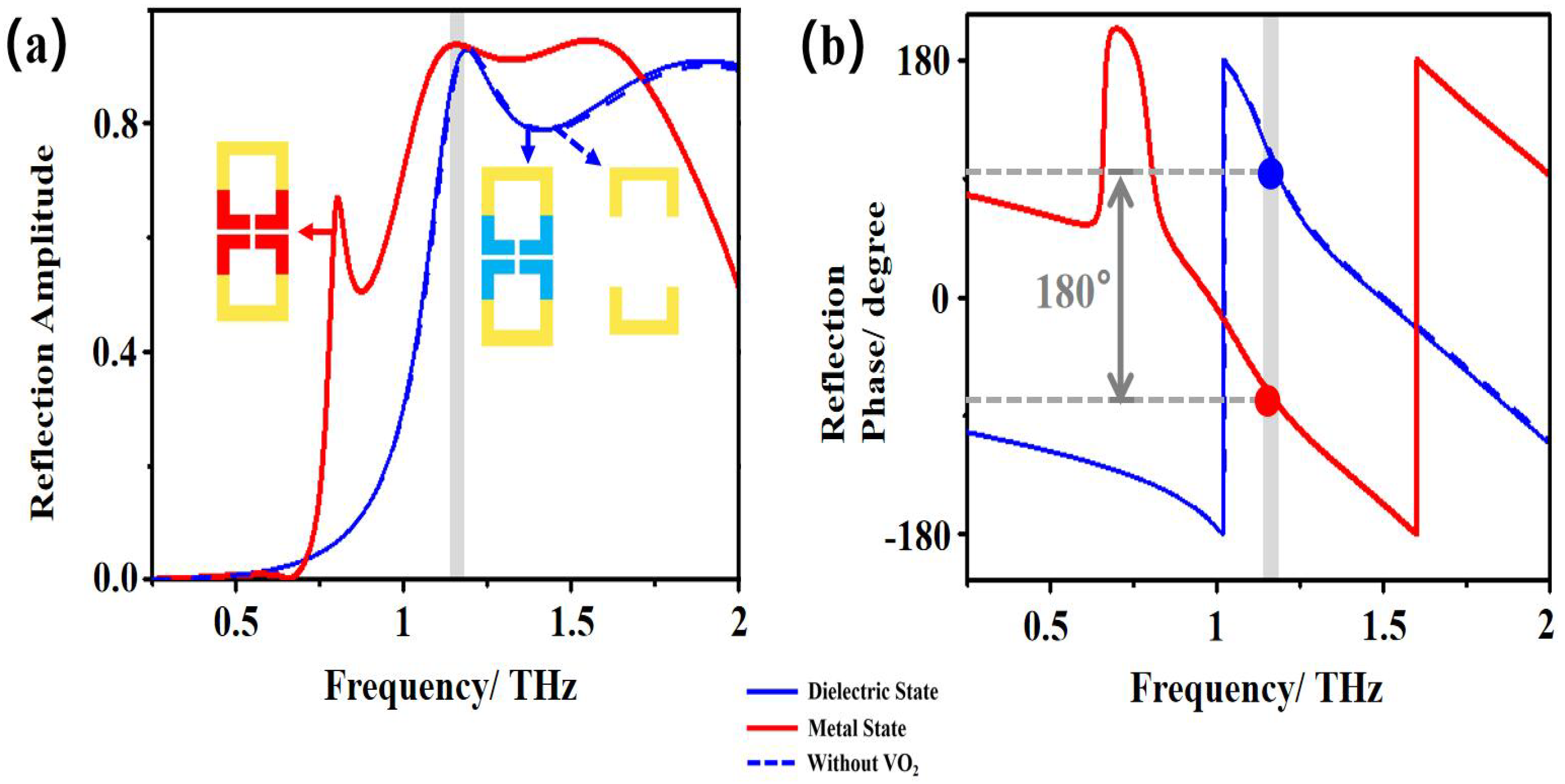
When α = 0°, we analyze the amplitude and phase properties of the unit cell for these three situations: including the dielectric V O 2 , including the metal V O 2 , and without V O 2 . The simulated results of the reflection amplitude and phase are shown in Figure 4a,b, respectively. At a frequency f, when V O 2 is in the two states, the dielectric state and the metal state, the reflection phase difference of the two corresponding unit cells is approximately 180°. Similarly, when α takes other values, the simulated reflection phase difference of the unit cells for the two states is approximately 180°, as well. It can be seen that, for two identical unit cells, but at low and high temperatures, respectively, they can be regarded as 1-bit coding unit cells [33]. What is more, regardless of the value of α , the reflection characteristics of the unit cell including the dielectric V O 2 and the unit cell without V O 2 are almost the same, and the latter ones rotating 135° and 45° conform to the characteristics of 1-bit coding units, which can be named as coding units “2” and “3”, respectively.
As mentioned above, the coding unit cells (including V O 2 ) rotating 135° and 45° counterclockwise are named as units “0” and “1”, and the unit cells (without V O 2 ) rotating 135° and 45° counterclockwise are named as units “2” and “3”. In Figure 5, the structural schematic diagrams of these four coding units are represented, and the corresponding coding states of these coding unit cells at high temperature and low temperature are, respectively, shown, as well. There are two situations that can be considered as 1-bit coding units: (1) two identical unit cells, but at low and high temperatures, respectively; (2) for the same temperature, two unit cells of the same structure, but rotated at different angles ( α = 135° and 45°). Additionally, for any unit cell without V O 2 , its corresponding coding state is constant at different temperatures.

3. Design and Analyses of the OAM Manipulation Metasurface

The vortex beam is known as the OAM beam, which is a kind of beam with a helical distribution of the phase front and a central field intensity of 0 [34]. The topological charges of OAM beams are orthogonal to each other, and these beams provide infinite channels for the communication system without increasing the frequency bandwidth. To generate an OAM beam whose topological charge is l, the phase of the unit (m, n) satisfies [35]:
φ ( m , n ) = φ 0 + l θ m n + 2 π λ | r m n r f |
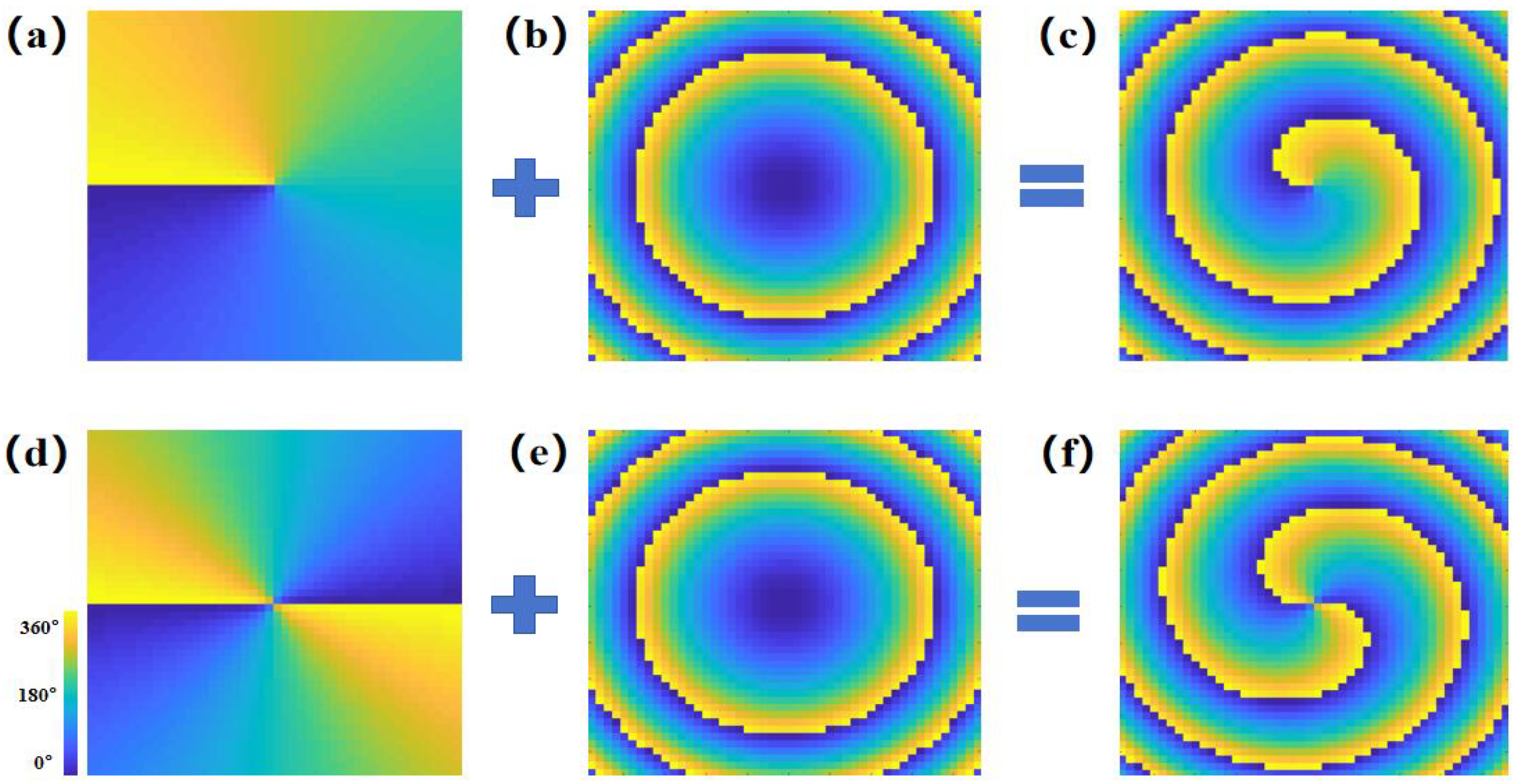
Clearly, from Equation (2), the phase φ ( m , n ) of the unit ( m , n ) consists of three parts: the initial phase φ 0 , the phase of the OAM beam l θ m n , and the compensation phase of the incident wave 2 π | r m n r f |/ λ . Additionally, θ m n is the azimuth of the unit (m, n), λ is the length of the incident wave, and r m n and r f are the position vectors of the unit (m, n) and the incident wave, respectively. Considering φ 0 = 0, for the metasurface with the function of OAM generation, the phase distributions of different parts of φ ( m , n ) are represented in Figure 6.
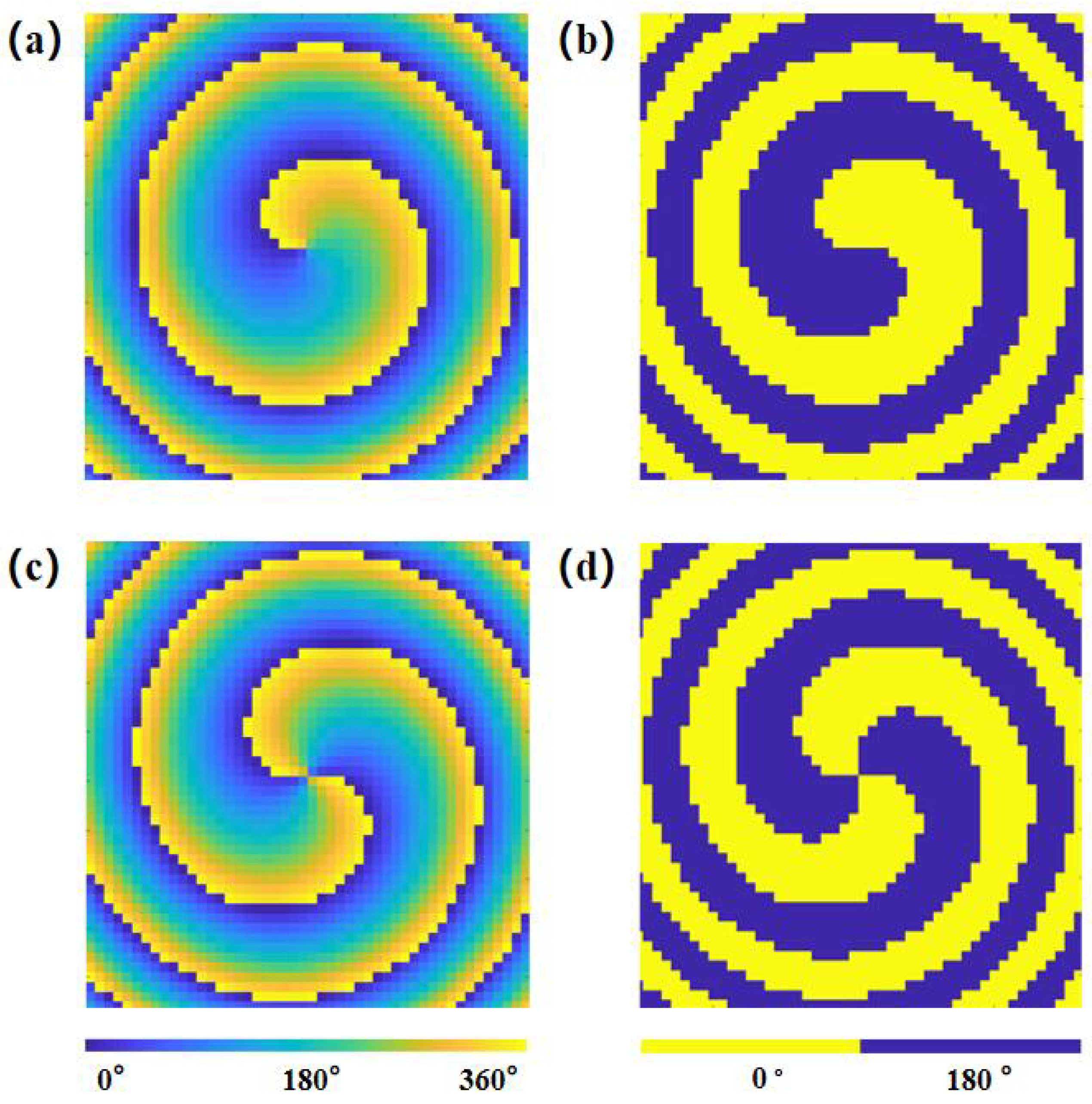
According to the principle of OAM generation, to manipulate the order of the generated OAM beam, a coding metasurface with 48 rows and 48 columns is designed to realize the expected function, which works at a frequency f. Figure 7a,c show the theoretical phase distributions of the l = −1 OAM beam and l = −2 OAM beam [36] generated by the 48 × 48 metasurface, while the designed metasurface in this paper is implemented by 1-bit coding; the corresponding phase distributions are shown in Figure 7b,d, where dark blue and yellow represent the reflection phase of 0° and 180°, respectively. By comparing the phase distributions for generating OAM beams of two orders in Figure 7b,d, it can be seen that, when the state of V O 2 changes, the reflection phases of the units are unchanged somewhere on the metasurface; thus, these unit cells ought to be designed without V O 2 in theory.
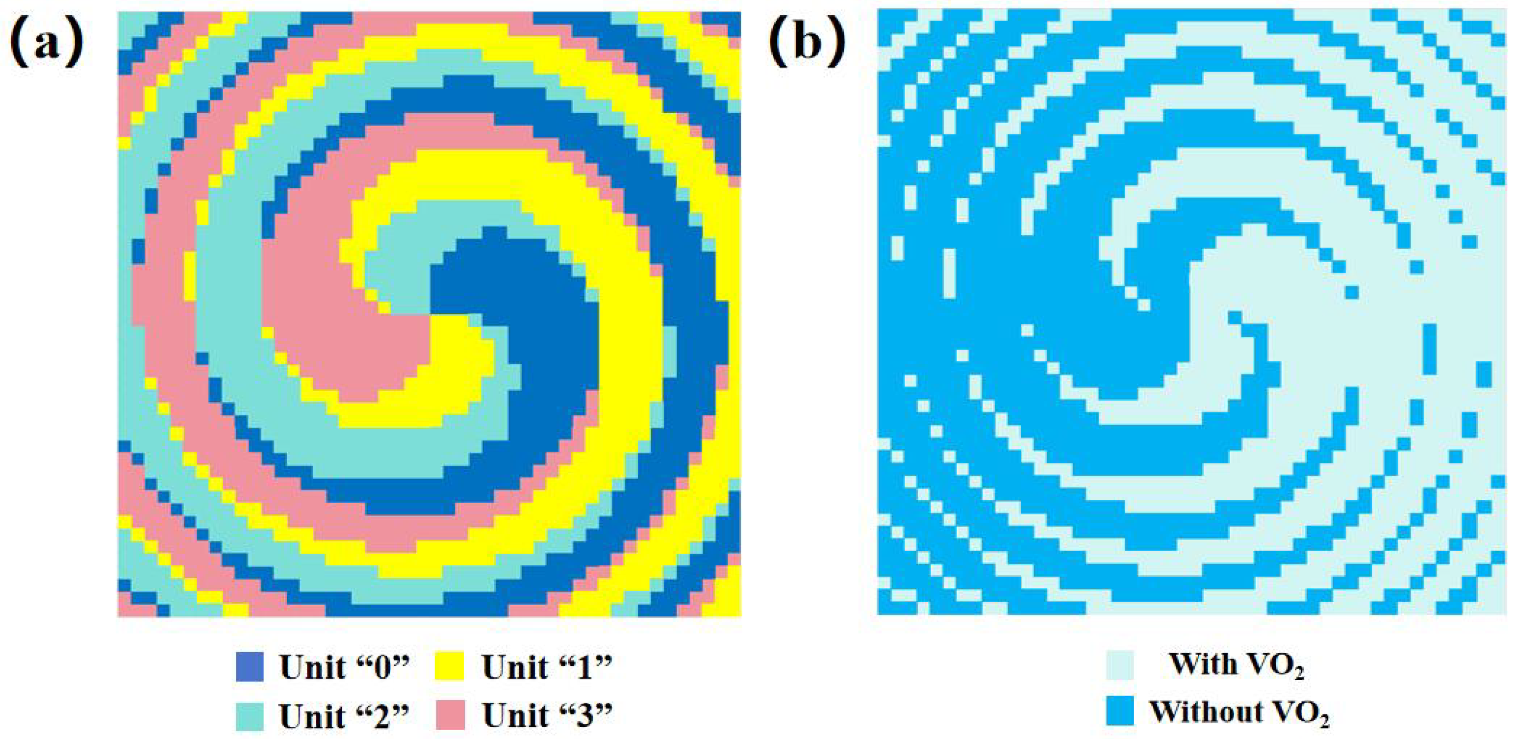
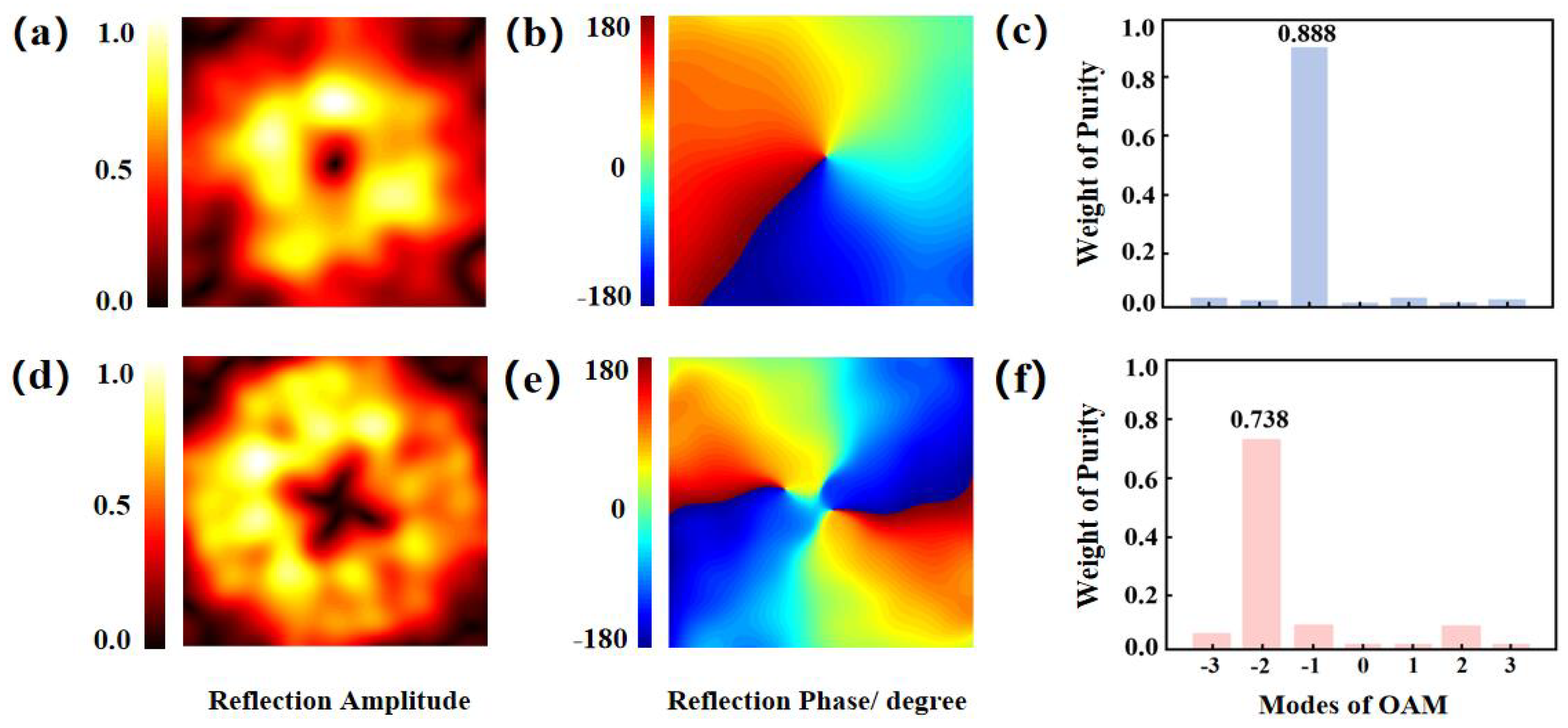
Figure 8 shows the arrangement sequence of the designed 48 × 48 metasurface; Figure 8b represents the array, which is made up of units with and without V O 2 , and the 1-bit coding metasurface includes four kinds of units, “0”, “1”, “2”, and “3”, whose arrangement sequence is represented in Figure 8a. As shown in Figure 9, the near-field simulated results of the 48 × 48 coding metasurface are analyzed when the RCP wave is incident on the metasurface in the −z direction. When V O 2 is in dielectric state, the metasurface can generate the l = −1 OAM beam; if the state of V O 2 changes to the metal state, the order of the generated OAM beam changes to −2. Figure 9a,b represent the near-field normalized reflection amplitude and phase diagrams of the generated l = −1 OAM beam; Figure 9d,e represent the near-field reflection properties of the l = −2 OAM beam. As observed in Figure 9a,b, it can be seen that the central electric field intensity of the OAM beams is approximately 0, and the distribution of the surrounding electric field intensity is stronger than the central one. In other words, the amplitude represents the typical doughnut-shaped OAM characteristics. On the other hand, Figure 9b,e represent equal-phase surfaces, respectively, covering the 2 π and 4 π range of the phase and rotating helically around the center, which accords with the phase distribution characteristics of the l = −1 OAM beam and l = −2 OAM beam.
The OAM beam contains other mode components except the main mode in the propagation process, and the quality of the generated beam generally decreases with the increase of the transmission distance. In this paper, a numerical simulation platform is used to calculate the purity of the OAM beam generated by the metasurface. Taking the position whose amplitude is zero as the center of the metasurface, a Fourier transform is performed on the toroidal electric field. The amplitude of the corresponding mode l can be expressed as [37]:
A l = 1 2 π 0 2 π ψ ( φ ) d φ e i l φ
ψ ( φ ) = l A l e i l φ
Equation (4) is the expression of the function of the sampling field, and the purity of the generated OAM beam can be characterized by the proportion of each of the modal energies to the total energy W E :
W E = A l l = N N A l e i l φ
In Equation (5), N represents the number of all patterns with different modes, where N = 3 in this paper. The main mode can be determined by the purity ratio of different modes. The higher the proportion of the main mode, the better the quality of the generated OAM beam is. For the metasurface with V O 2 in the two different states, Figure 9c,f represent the calculated mode purities of the generated OAM beam. The purities of the main modes reach 88.8% and 73.8%, corresponding to the generated l = −1 OAM beam and l = −2 OAM beam. Since other modes have much less energy than the main mode, their interference can be ignored.

4. Conclusions

In this paper, an active digitally coding metasurface in the terahertz-frequency band is designed based on V O 2 . The top of the unit cell consists of two SSRRs with two gaps, which are in opposite directions. By adjusting the state of V O 2 from the dielectric state to the metal state, the resonant mode of the unit cell changes from microstrip resonance to LC resonance, correspondingly. According to the principle of the P-B phase, the designed coding metasurface can actively control the terahertz circularly polarized waves in the near field, which can realize active control of the order of the generated OAM beams with high mode purity. It probably has important application values in wireless communication, radar, and other fields.

Author Contributions

Conceptualization, T.P. and F.Y.; methodology, T.P.; software, T.P.; validation, T.P. and C.L.; formal analysis, T.P. and C.L.; investigation, C.L. and S.P.; resources, T.P.; writing—original draft preparation, T.P.; writing—review and editing, C.L., H.L., T.P. and F.Y.; visualization, H.Z., X.X. and C.L.; supervision, F.Y.; project administration, F.Y. All authors have read and agreed to the published version of the manuscript.

Funding

This work was supported in part by the National Natural Science Foundation of China (Grant No. 12173008), the National Key R&D Program of China (Grant No. 2018YFF0109302, Grant No. 2018YFB1801505), the Aeronautical Science Foundation of China (Grant No. 201920069002), and by the Foundation of Science and Technology on Monolithic Integrated Circuits and Modules Laboratory (Grant No. 614280302032105).

Institutional Review Board Statement

Not applicable.

Informed Consent Statement

Not applicable.

Data Availability Statement

The data underlying the results presented in this paper are not publicly available at this time, but may be obtained from the authors upon reasonable request.

Conflicts of Interest

The authors declare no conflicts of interest.

Abbreviations

The following abbreviations are used in this manuscript:
V O 2 vanadium dioxide
EMTeffective media theory
P-B phasePancharatnam-Berry phase
SSRRsplit square resonant ring
FDTDFinite-Difference Time Domain
RCPright-handed circularly polarized
OAMorbital angular momentum

References

  1. Shin, J.-H.; Park, K.-H.; Ryu, H.-C. A Band-Switchable and Tunable THz Metamaterial Based on an Etched Vanadium Dioxide Thin Film. Photonics 2022, 9, 89. [Google Scholar] [CrossRef]
  2. Jiang, Z.-X.; Leng, J.; Li, J.; Li, J.-F.; Li, B.-Y.; Yang, M.; Wang, X.-L.; Shi, Q.-W. Flexible Terahertz Metamaterials Absorber based on VO2. Photonics 2023, 10, 621. [Google Scholar] [CrossRef]
  3. Shabanpour, J.; Beyraghi, S.; Cheldavi, A. Ultrafast reprogrammable multifunctional vanadium- dioxide- assisted metasurface for dynamic THz wavefront engineering. Sci. Rep. 2020, 10, 8950. [Google Scholar] [CrossRef]
  4. Liang, S.; Xu, F.; Li, W.; Yang, W.; Cheng, S.; Yang, H.; Chen, J.; Yi, Z.; Jiang, P. Tunable smart mid infrared thermal control emitter based on phase change material VO2 thin film. Appl. Therm. Eng 2023, 232, 121074. [Google Scholar] [CrossRef]
  5. Li, W.; Cheng, S.; Zhang, H.; Yi, Z.; Tang, B.; Ma, C.; Wu, P.; Zeng, Q.; Raza, R. Multi-functional metasurface: Ultra-wideband/multi-band absorption switching by adjusting guided mode resonance and local surface plasmon resonance effects. Commun. Theor. Phys. 2024, 76, 065701. [Google Scholar] [CrossRef]
  6. Bang, S.; Kim, J.; Yoon, G.; Tanaka, T.; Rho, J. Recent Advances in Tunable and Reconfigurable Metamaterials. Micromachines 2018, 9, 560. [Google Scholar] [CrossRef]
  7. Luo, J. Manipulations of Electromagnetic Waves by Coding Metamaterials and Their Applications. Master’s Thesis, Southeast University, Nanjing, China, 2019. [Google Scholar]
  8. Shangguan, Q.; Zhao, Y.; Song, Z.; Wang, J.; Yang, H.; Chen, J.; Liu, C.; Cheng, S.; Yang, W.; Yi, Z. High sensitivity active adjustable graphene absorber for refractive index sensing applications. Diam. Relat. Mater. 2022, 128, 109273. [Google Scholar] [CrossRef]
  9. Rouhi, K.; Rajabalipanah, H.; Abdolali, A. Multi-bit graphene-based bias-encoded metasurfaces for real-time terahertz wavefront shaping: From controllable orbital angular momentum generation toward arbitrary beam tailoring. Carbon 2019, 149, 125–138. [Google Scholar] [CrossRef]
  10. Wang, J.-L.; Dong, X.-C.; Yin, L.; Yang, Z.-X.; Wan, H.-D.; Chen, H.-M.; Zhong, K. Vanadium dioxide based terahertz dual-frequency multi-function coding metasurface. Acta Phys. Sin. 2023, 72, 098101. [Google Scholar] [CrossRef]
  11. Cui, T.-J.; Qi, M.-Q.; Wan, X.; Zhao, J.; Cheng, Q. Coding metamaterials, digital metamaterials and programmable metamaterials. Light Sci. Appl. 2014, 3, e218. [Google Scholar] [CrossRef]
  12. Jiang, W.-X.; Tian, H.-W.; Song, C.; Zhang, X.-G. Digital Coding Metasurfaces: Toward Programmable and Smart Manipulations of Electromagnetic Functions. J. Radars. 2022, 11, 1003–1022. [Google Scholar]
  13. Wang, L.; Yang, Y.; Gao, F.; Teng, S.-H.; Tan, Z.-G.; Zhang, X.; Lou, J.; Deng, L. Terahertz reconfigurable dielectric metasurface hybridized with vanadium dioxide for two-dimensional multichannel multiplexing. Front. Phys. 2022, 10, 992037. [Google Scholar] [CrossRef]
  14. Pan, Y.-B. Research on the Terahertz Vortex Beam Based on Coding Metasurface. Master’s Thesis, University of Electronic Science and Technology of China, Chengdu, China, 2022. [Google Scholar]
  15. Wang, L.; Yang, Y.; Deng, L.; Hong, W.-J.; Zhang, C.; Li, S.-F. Vanadium dioxide embedded frequency reconfigurable metasurface for multi-dimensional multiplexing of terahertz communication. J. Phys. D Appl. Phys. 2021, 54, 255003. [Google Scholar] [CrossRef]
  16. Chen, B.-W.; Wang, X.-R.; Li, W.-L.; Li, C.; Wang, Z.-S.; Guo, H.-B.; Wu, J.-B.; Fan, K.-B.; Zhang, C.-H.; He, Y.-B.; et al. Electrically addressable integrated intelligent terahertz metasurface. Sci. Adv. 2022, 8, eadd1296. [Google Scholar] [CrossRef]
  17. Li, J.-H.; Zhang, Y.-T.; Li, J.-N.; Li, J.; Li, J.-T.; Zheng, C.-L.; Yang, Y.; Huang, J.; Ma, Z.-Z.; Ma, C.-Q.; et al. Terahertz coding metasurface based vanadium dioxide. Acta Phys. Sin. 2020, 69, 228101. [Google Scholar] [CrossRef]
  18. Chen, B.-W.; Yang, S.-X.; Chen, J.; Wu, J.-B.; Chen, K.; Li, W.-L.; Tan, Y.-H.; Wang, Z.-S.; Qiu, H.-S.; Fan, K.-B.; et al. Directional terahertz holography with thermally active Janus metasurface. Light Sci. Appl. 2023, 12, 136. [Google Scholar] [CrossRef]
  19. Dong, J.-Q.; Cheng, Y.-Q.; Lin, S.-Y.; Zhou, Y.; Chen, Q. Reconfigurable Mode Vortex Beam Generation Based on Metasurface Using VO2 at Different Metal-Insulator Transition Temperatures. In Proceedings of the 2023 IEEE 11th Asia-Pacific Conference on Antennas and Propagation (APCAP), Guangzhou, China, 22 November 2024. [Google Scholar]
  20. Guan, S.-N.; Cheng, J.-R.; Chang, S.-J. Recent progress of terahertz spatial light modulators. Adv. Photonics Nexus. 2022, 13, 1637. [Google Scholar]
  21. Sırmacı, Y.D.; Barreda Gomez, A.; Pertsch, T.; Schmid, J.H.; Cheben, P.; Staude, I. All Dielectric Huygens’ Meta-Waveguides for Resonant Integrated Photonics. Laser Photonics Rev. 2023, 17, 2200860. [Google Scholar] [CrossRef]
  22. Bakker, R.M.; Yu, Y.F.; Paniagua-Domínguez, R.; Luk’yanchuk, B.; Kuznetsov, A.I. Resonant Light Guiding Along a Chain of Silicon Nanoparticles. Nano Lett. 2017, 17, 3458–3464. [Google Scholar] [CrossRef]
  23. Qiu, R.; Zhang, G.-M.; Zhang, Q.; Zhu, J.-C.; Feng, Y.-H.; Du, S.-K.; Liu, J.; Bi, K.-Y. Vanadium dioxide-based broadband spin-decoupled metasurface for wavefront control and modulation. Opt. Commun. 2023, 545, 129399. [Google Scholar] [CrossRef]
  24. Yang, J.-K.; Jeong, H.-S. Switchable Metasurface with VO2 Thin Film at Visible Light by Changing Temperature. Photonics 2021, 8, 57. [Google Scholar] [CrossRef]
  25. Drude, P. Zur Elektronentheorie der Metalle. Ann. Phys. 1900, 306, 566–613. [Google Scholar] [CrossRef]
  26. Verleur, H.W.; Barker, A.S., Jr.; Berglund, C.N. Optical Properties of VO2 between 0.25 and 5 eV. Phys. Rev. 1968, 172, 788–798. [Google Scholar] [CrossRef]
  27. Zhang, C.-H.; Zhou, G.-C.; Wu, J.-B.; Tang, Y.-H.; Wen, Q.-Y.; Li, S.-X.; Han, J.-G.; Jin, B.-B.; Chen, J.; Wu, P.-H. Active Control of Terahertz Waves Using Vanadium-Dioxide-Embedded Metamaterials. Phys. Rev. Appl. 2019, 11, 054016. [Google Scholar] [CrossRef]
  28. Spanos, I.; Stevens, C.J.; Solymar, L.; Shamonina, E. Tailoring the dispersion characteristics in planar arrays of discrete and coalesced split ring resonators. Sci. Rep. 2023, 13, 19981. [Google Scholar] [CrossRef]
  29. Lv, X.; Li, C.; Que, Y.; Li, G.; Hou, X.; Li, Y.; Li, L.; Sun, Y.; Guo, Y. Experimental demonstration of broadband impedance matching using coupled electromagnetic resonators. Sci. Rep. 2020, 10, 7437. [Google Scholar] [CrossRef]
  30. Liao, H.; Li, J.-S.; Guo, Y.-S. Theoretical and experimental study of the electric resonant coupling between two metamaterial resonators. Acta Phys. Sin. 2015, 64, 144101. [Google Scholar]
  31. Li, J.; Yang, Y.; Li, J.-N.; Zhang, Y.-T.; Zhang, Z.; Zhao, H.-L.; Li, F.-Y.; Tang, T.-T.; Dai, H.-T.; Yao, J.-Q. All-optical Switchable Vanadium Dioxide Integrated Coding Metasurfaces for Wavefront and Polarization Manipulation of Terahertz Beams. Adv. Theory Simul. 2019, 3, 1900183. [Google Scholar] [CrossRef]
  32. Liu, J.-Q.; Cheng, Y.-Z.; Chen, F.; Luo, H.; Li, X.-C. High- Efficiency wavefront manipulation based on geometric phase metasurface for circularly polarized terahertz wave at two frequencies dependently. Infrared Laser Eng. 2023, 52, 20220377. [Google Scholar]
  33. Li, J.; Li, J.-T.; Zhang, Y.-T.; Li, J.-N.; Yang, Y.; Zhao, H.-L.; Zheng, C.-L.; Li, J.-H.; Huang, J.; Li, F.-Y.; et al. All-optical switchable terahertz spin-photonic devices based on vanadium dioxide integrated metasurfaces. Opt. Commun. 2020, 460, 124986. [Google Scholar] [CrossRef]
  34. Yang, D.-Q.; Wang, W.-G.; Lv, E.; Wang, H.-M.; Liu, B.-C.; Hou, Y.-Z.; Chen, J.-H. Programmable VO2 metasurface for terahertz wave beam steering. iScience 2022, 25, 104824. [Google Scholar] [CrossRef]
  35. Liu, C.-X.; Yang, F.; Fu, X.-J.; Wu, J.-W.; Zhang, L.; Yang, J.; Cui, T.-J. Programmable Manipulations of Terahertz Beams by Transmissive Digital Coding Metasurfaces Based on Liquid Crystals. Adv. Optical Mater. 2021, 9, 2100932. [Google Scholar] [CrossRef]
  36. Li, X.-N.; Zhou, L.; Zhao, G.-Z. Terahertz vortex beam generation based on reflective metasurface. Acta Phys. Sin. 2019, 68, 238101. [Google Scholar] [CrossRef]
  37. Han, X.-B.; Chen, J.-X.; Wang, Y.; Zhou, Y.-G. Terahertz orbital angular momentum generation based on ultra-wideband reflective metasurface. J. Appl. Opt. 2024, 45, 282–291. [Google Scholar]
Figure 1. Schematic diagram of the unit cell. (a) The top view and (b) the side view of the unit cell.
Photonics 11 00527 g001
Figure 2. The distributions of electric field intensity and equivalent structural diagrams for the top patterned layer of the unit cell. For the unit cells with V O 2 in (a) the dielectric state and (c) the metal state, the corresponding distribution of electric field intensity in the top patterned layer is given. Equivalent structural diagrams of the top layer of the unit cell with (b) the dielectric V O 2 and (d) the metal V O 2 .
Photonics 11 00527 g002
Figure 3. The reflection characteristics of the unit cells. The reflection amplitude and phase of the unit when V O 2 is in (a) the dielectric state and (b) the metal state for different values of rotation angle α , and the incident wave is the RCP wave in the −z direction.
Photonics 11 00527 g003
Figure 4. The reflection characteristics of the unit cell when V O 2 is in the two different states. For V O 2 in the dielectric state, V O 2 in the metal state, and without V O 2 , the (a) reflection amplitude and (b) reflection phase of the unit cell (the case of rotation angle α = 0°).
Photonics 11 00527 g004
Figure 5. The schematic diagram of four coding units and their corresponding coding states (“0” or “1”) at a low and a high temperature. (a) Four coding units “0”, “1”, “2”, and “3”; (b) at a low temperature, the coding states for four coding units (the blue part represents the dielectric V O 2 ); (c) at a high temperature, the coding states for four coding units (the red part represents the metal V O 2 ).
Photonics 11 00527 g005
Figure 6. Phase distribution of the metasurfaces with the function of generating l = −1 and l = −2 OAM beams (l is the order of the generated OAM beams). Theoretical phase distribution of the metasurfaces generating the (a) l = −1 OAM beam and (d) l = −2 OAM beam; compensation phase distribution of the metasurfaces generating the (b) l = −1 OAM beam and (e) l = −2 OAM beam; phase distribution of the phase-compensated metasurfaces generating the (c) l = −1 OAM beam and (f) l = −2 OAM beam.
Photonics 11 00527 g006
Figure 7. Phase distributions of OAM beams with different orders. Theoretical phase distributions of the (a) l = −1 OAM beam and (c) l = −2 OAM beam; 1-bit coding phase distribution of the (b) l = −1 OAM beam and (d) l = −2 OAM beam.
Photonics 11 00527 g007
Figure 8. The arrangement of the designed OAM manipulation metasurface. The arrangement of (a) 1-bit coding units and (b) units with and without V O 2 .
Photonics 11 00527 g008
Figure 9. Near-field simulation results of the designed OAM-manipulating metasurface. For the metasurface, when V O 2 is in the dielectric state, near-field normalization (a) amplitude and the (b) phase and (c) mode purity of the generated l = −1 OAM beam. When V O 2 is in the metal state, the near-field normalization (d) amplitude and (e) phase and (f) mode purity of the generated l = −2 OAM beam.
Photonics 11 00527 g009
Disclaimer/Publisher’s Note: The statements, opinions and data contained in all publications are solely those of the individual author(s) and contributor(s) and not of MDPI and/or the editor(s). MDPI and/or the editor(s) disclaim responsibility for any injury to people or property resulting from any ideas, methods, instructions or products referred to in the content.