Article

Optimized Wide-Angle Metamaterial Edge Filters: Enhanced Performance with Multi-Layer Designs and Anti-Reflection Coatings

1
School of Computer Science and Engineering, Bangor University, Dean Street, Bangor LL57 1UT, UK
2
School of Physics and Astronomy, University of Southampton, Southampton SO17 1BJ, UK
3
Qioptiq Ltd., St Asaph, LL17 0LL, UK
*
Author to whom correspondence should be addressed.
Photonics 2024, 11(5), 446; https://doi.org/10.3390/photonics11050446
Submission received: 19 April 2024 / Revised: 6 May 2024 / Accepted: 8 May 2024 / Published: 10 May 2024
(This article belongs to the Special Issue Emerging Trends in Metamaterials and Metasurfaces Research)

Abstract

:
This study presents a systematic optimization of wide-angle metamaterial long-pass (LP) edge filters based on silicon nanospheres (SiNP). Multi-layered configurations incorporating SiNP-meta-films and anti-reflection coating (ARC) elements not previously considered in the literature are explored to enhance their filter performance in both stop and pass bands. This research has successfully developed an accurate model for the effective refractive index using Kramers–Kronig relations, enabling the use of classical thin-film design software for rapid device performance optimization, which is verified by full-wave numerical software. This systematic optimization has produced highly efficient, near-shift-free long-pass metamaterial filters, evidenced by their high optical density (OD = 2.55) and low spectral shift across a wide angular range (0°–60°). These advancements herald the development of high-efficiency metamaterial optical components suitable for a variety of applications that require a consistent performance across diverse angles of incidence.

1. Introduction

Optical filters are crucial components that can reflect, absorb, and transmit electromagnetic (EM) waves simultaneously or selectively within specific wavelength ranges [1]. They have widespread application in various fields, including medical imaging, industrial manufacturing, electronics, defense, and scientific research [2,3,4]. These filters are primarily categorized as thin-film filters and colored absorptive filters, each with unique working characteristics [1,5]. Traditional thin-film filters employ alternating layers of transparent materials with varying high/low refractive indices to produce destructive and constructive interferences among the reflected and transmitted light components. This mechanism results in the desired spectra for reflectance and transmittance. However, these thin-film filters generally operate within a limited range of incident angles. This is because the phenomenon known as ‘blue shift’ occurs when the filter experiences a high incidence angle, where the filter ceases to function as intended [6]. As a result, there is a substantial demand for the development of shift-free wide-angle filters for industrial applications. Such filters are critical in applications that demand a consistent optical performance across different viewing angles, including spectroscopy, astronomy, photography, and optical communication. Shift-free wide-angle filters ensure the stability of the spectral characteristics, regardless of the light’s direction of incidence, thereby preventing spectral distortions and guaranteeing accurate data in scientific, imaging, and sensing applications. They also play a vital role in improving safety in laser protection and expanding the versatility of filters in scenarios where the incident angle might change unpredictably, rendering them indispensable in numerous optical systems.
While shift-free wide-angle capabilities might be attainable with absorptive filters using colored organic dyes or pigments, these tend to be substantially thicker, in order to ensure effective light blocking. Furthermore, their organic materials may deteriorate in harsh working environments [7]. Such filters are not within the scope of this study.
To achieve shift-free wide-angle performance in thin-film filters, one method involves using materials with high-contrast refractive indices and slightly absorptive components in their design. For example, Ji et al. showcased a long-pass (LP) edge filter (with cut-on wavelength, λ Cut-on ~700 nm, transition band: 700 nm–900 nm) consisting of alternately stacked layers of amorphous silicon/silicon nitride (α-Si/SiN) [7]. The filter’s enhanced angular performance stemmed from the high-contrast refractive indices (α-Si = 4.4 + i0.27, S i N = 1.9 at 550 nm) and the slightly absorptive nature of α-Si in the stop band. However, the tunability of the cut-on wavelength λ Cut-on in this design is limited, restricting its application. A more versatile solution can be found in metamaterials in the form of artificially engineered nanomaterials, whose unique properties arise from their sub-wavelength structural configurations rather than their chemical composition [8,9,10]. Therefore, the optical property of the metamaterials can be tuned to meet specifical requirements, as long as we change the geometry parameters of the sub-wavelength structural configurations [11,12,13].
In 2018, our group introduced the first shift-free nanoparticle-based metamaterial notch-filter capable of effectively blocking a Class 3B 532 nm green laser with an optical density (OD) of 1.88+ for all polarization states and incident angles of up to 85° [14]. The design includes an anti-reflection layer, an active blocking layer based on silver nanoparticles (AgNP), and a substrate. Subsequently, in 2019, Lotti et al. showcased a small-shift metamaterial edge filter based on silicon nanoparticles (SiNP) [15]. However, their designs have not been tailored for practical applications, as considerations for substrates and anti-reflective coating (ARC) designs were absent. Furthermore, the performance of their filters is not yet optimal, exhibiting insufficient blocking in the stop band (<400 nm) and limited transmission in the passing band (>900 nm). Our objective is to overcome these shortcomings by significantly enhancing the edge filter performance across the entire design band of 400–1200 nm. In this work, we introduce a multi-layer design that can significantly increase the blocking performance in the stop band, as well as the application of an ARC design to substantially boost the transmission performance in the long-wavelength pass band. This innovation yields an edge filter that surpasses all other reported metamaterial filters in the literature, delivering a high optical density (OD = 2.55, 0.28%) with minimal spectral shift across an extensive angular range (0°–60°). Such a performance is crucial for a multitude of applications that demand consistent results over various angles of incidence.

2. Design Methods and Models

2.1. Design Methods

Our design methodology combines the computational strengths of full-wave simulation software computational simulation technology (CST, version 2022) with the classical thin-film design capabilities of Essential Macleod (ESM, version 10.2) for the optimized design of ARC and optical meta-film layers (MFLs). The stages are as follows:
  • CST Simulation of Optical MFL: We began with CST simulations to accurately characterize the spectral profiles of the SiNP-based MFL. This involved parameter sweeps in the unit cell models, altering periodicity, nanoparticle size, and the properties of the host medium.
  • Effective Refractive Index Calculation: We then extracted the effective refractive index from the CST simulation outcomes, a critical factor for adapting the CST model to an ESM-compatible format.
  • Multi-Layer and ARC Design Optimization in ESM: Using the effective refractive index, we converted the CST models into the ESM platform and employed the needle synthesis function for the efficient optimization of multi-layer designs ( H 0 and H 3 in this case), including the introduction of the ARC. During synthesis, we locked the refractive index and thickness of all of the MFLs. A target reflection from 425 nm to 1200 nm, with a step width of 25 nm, was set to attain 0 at 0 ° , 30 ° , and 60 ° AOI in transverse electric (TE) polarization. No need was found to set transverse magnetic (TM) polarization, as the transmission of the filter in this model is naturally considerable in all AOIs.
  • CST Verification and Fine-Tuning: Subsequently, we refined the designs derived from the ESM using CST simulations to finalize an enhanced design, ensuring superior performance metrics.
The rationale behind this integrative approach was to address the time-intensive nature of CST simulations, which are otherwise prohibitive for extensive design and optimization exercises. Once we ascertained the effective refractive index using the Kramers–Kronig (K–K model), which was selected for its precision, we employed ESM for its rapid processing and robust algorithms. The final design adjustments were made with CST to confirm that our designs surpassed conventional standards, achieving a greater optical density of up to a value of 2.55 and a notably reduced spectral shift, which diminished by up to 50% across a broad angular spectrum from 0° to 60°.

2.2. Models for Effective Refractive Index

The following two models were tested and compared to calculate the effective refractive index ( n e f f ) of the MFLs: the Bruggeman approximation and K–K approximation [16,17].
The Bruggeman approximation is based on the following:
i = 1 m f i n i 2 n e f f 2 n i 2 + 2 n e f f 2 = 0
where f i represents the volume fraction and ni is the refractive index of the ith constituent material within the MFL composed of host materials.
In the K–K approximation, the effective extinction coefficient ( k e f f ) of the MFLs was initially determined by the following equation:
1 R T = e x p ( 4 π k e f f d / λ )
where R and T are the reflectance and transmittance spectra obtained from the CST simulations, respectively, λ is the incidence wavelength, and d is the meta-film thickness.
The K–K relations enable the determination of one part of a complex refractive index at any given frequency ( ω ), as long as the other part is known over the entire frequency range ( ω ). After this, the following equation was employed to calculate the real part of the complex refractive index [18]:
n e f f ( ω ) = n + 2 π P 0 ω k e f f ( ω ) ω 2 ω 2 d ω
Here, n denotes the refractive index of the host medium with the integral in Equation (3), computed using the Hilbert transform method, and P is the Cauchy principal value. The comparison results between the Bruggeman and K–K models are detailed in the Section 3.

2.3. Designs

Figure 1 presents the designs used in this study, focusing on the integration of SiNPs within various configurations, as follows:
(a) The foundational design features a single SiNP within a host medium.
(b) The single-layered unit cell arrays SiNPs homogeneously, exploring basic optical manipulations.
(c,d) Multi-layered variants stack such units to refine the edge characteristics.
(e) The final design adds magnesium fluoride ( M g F 2 ) as the ARC, with the thickness determined by ESM, to the multi-layer structure, optimizing transmission.
We chose M g F 2 as the material for the ARC due to its low refractive index (~1.38), which falls between the refractive index of the air and meta-layers. Additionally, it offers high transparency across a broad wavelength range from UV to IR bands and stable mechanical properties [19].
We categorize the designs as follows:
LP0 is the configuration of a conventional edge filter, which uses S i N and M g F 2 as high- and low-index materials with a refractive index from reference [20,21], respectively. LP1–LP4 are all composed of infinite unit cells in a primitive cubic lattice configuration with a fixed period of D = 145 nm. In each MFL, one unit cell consists of a SiNP with a radius of R = 60 nm and a refractive index from reference [22] embedded in the dielectric S i N host medium and a glass substrate [23]. The dispersion of all used materials was considered, and the corresponding wavelength-dependent refractive indexes are depicted in Figure S1. The numerical simulations conducted using CST employed a mesh accuracy of λ/10 for the host material and R/5 for the SiNPs, with a wavelength ranging from 350 nm to 1200 nm. The distance of the incident port is three times the length of the longest wavelength (1200 nm), totaling 3600 nm. The output port is directly connected to the bottom surface of the substrate to emulate a thick substrate of more than 100 μm thick.
The ARC design process leverages the ESM software’s needle synthesis function, which differs from the simple quarter-wave design at one wavelength. Specifically, ESM incorporates the effective index of the MFL and employs needle synthesis for calculating the anti-reflective coating, with the capability of targeting multiple transmission peaks across various wavelengths, rather than optimizing for a single wavelength.
In this paper, the term ‘stop band’ (350 nm–480 nm) denotes the band where the optical density (OD = l o g T ) exceeds 1, while the edge wavelength (λedge) is defined as the wavelength where T equals 0.5Tpeak. The pass band extends from the edge wavelength to 1200 nm.

3. Results and Discussion

In this section, we first present a classical thin-film edge filter along with its angular performance to illustrate its ‘blue shift’ problem. Subsequently, we show why we have chosen the K–K model as an effective refractive index model in this research. This is followed by the key results from metamaterial designs LP1–LP4.

3.1. Traditional Thin-Film Filters

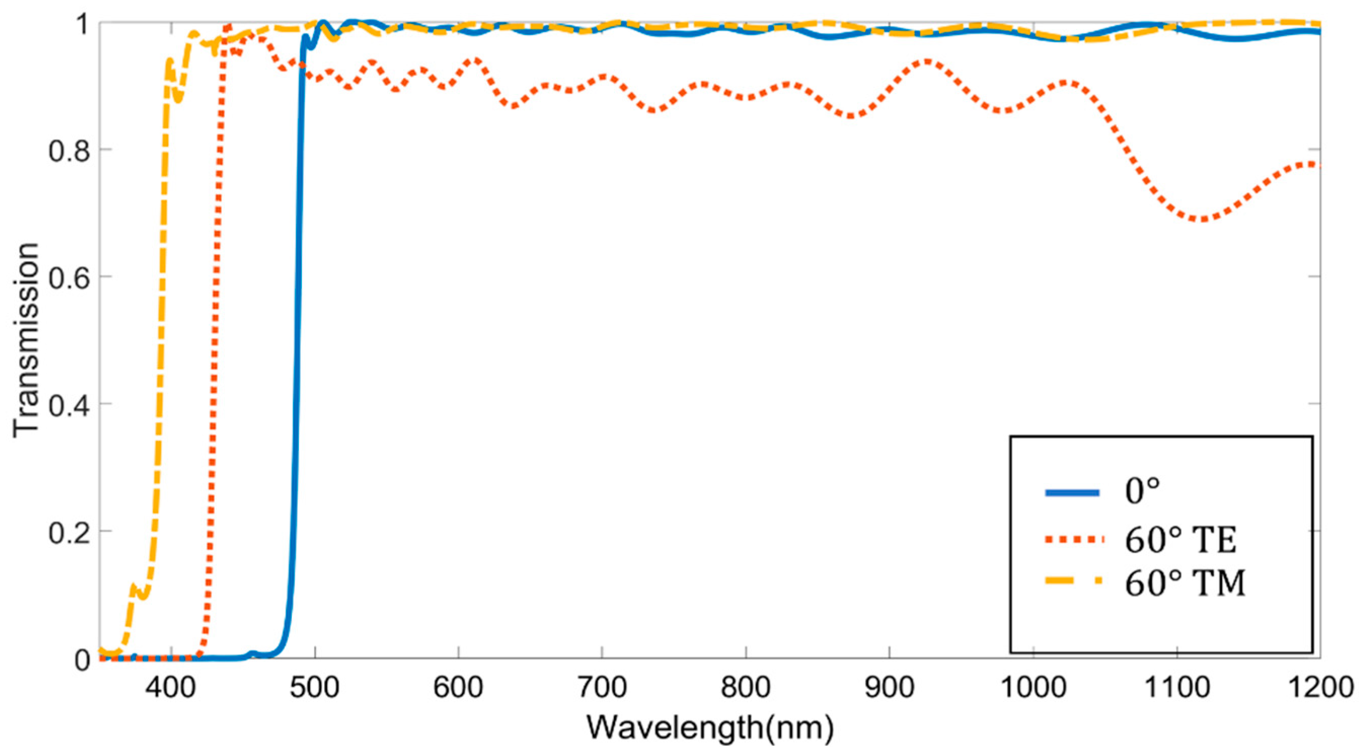
Figure 2 depicts the transmission spectra of a conventional edge filter (LP0 design) based on classical thin-film technology. It consists of 49 layers of high and low refractive index materials, and its configuration is shown in Table 1, in which the quarter-wavelength thicknesses of the high ( S i N ) and low index ( M g F 2 ) material (with 445 nm as a reference wavelength) are represented as H and L, respectively. The constant 0.8 allows the edge wavelength to be tuned to approximately 500 nm.
The blue shift of the spectrum is approximately 80 nm when the incident angle is increased from 0° to 60° s for the transverse electric (TE) waves and 100 nm for the transverse magnetic (TM) waves. The blue shift in the thin-film filters at increased angles of incidence results from changes in phase thickness and the variation of effective admittance, influenced by the Brewster angle, which separates the band edges at higher angles [24]. This shift does not satisfy the requirements for numerous applications. Ideally, the wavelength shift should be less than 10 nm for it to be suitable for practical applications.

3.2. K–K Model and Bruggeman Model

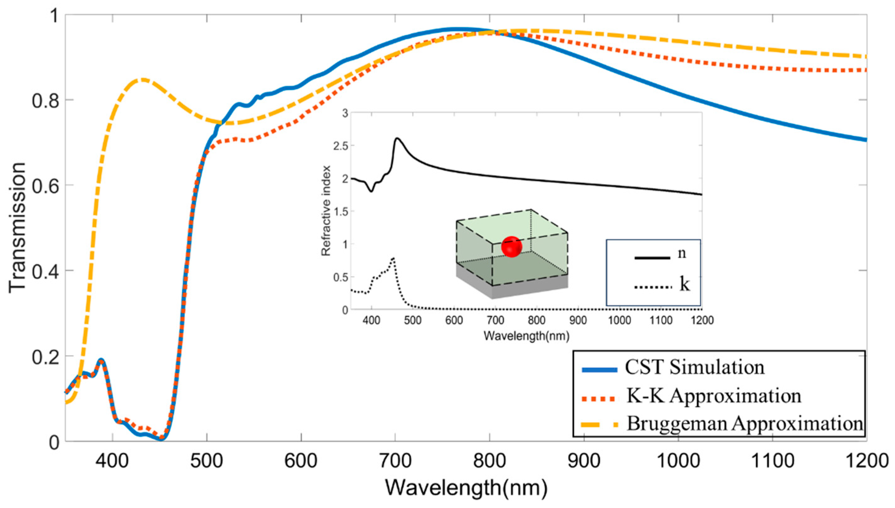
The LP1 design (Figure 1b) was used as the base to calculate the effective refractive index of the MFL. Figure 3 presents the transmission spectra calculated by CST, the Bruggeman approximation, and the K–K model, respectively. The curve derived from the Bruggeman approximation demonstrates a mismatch of the λ Cut-on when compared to the results from the CST and those indirectly obtained from the K–K model. The Bruggeman approximation, as described in Equation (1), is thus not suitable for this study, due to its failure to account for the strong near-field interplay between adjacent particles.
The transmission spectrum of an MFL employing the refractive index that derived from K–K model shows reasonably good agreement with the CST spectrum, particularly in the short-wavelength bands and at the edge wavelength. Across the entire wavelength spectrum, the average mean square error (MSE) of the transmission obtained via the K–K model is 0.00053. This is approximately one order of magnitude lower than the MSE of the Bruggeman approximation (0.00692). Therefore, the K–K model can provide a more precise approximation of the effective refractive index.
Although some deviations are present in the longer wavelength bands, the K–K model captures the main physical phenomena at the edge wavelength, which is crucial for this work. Consequently, it is utilized in our design process. The designs optimized using the K–K model in the ESM are subsequently fine-tuned and verified by CST software, which circumvents the discrepancies between the two software suites.

3.3. Metamaterial Edge Filters

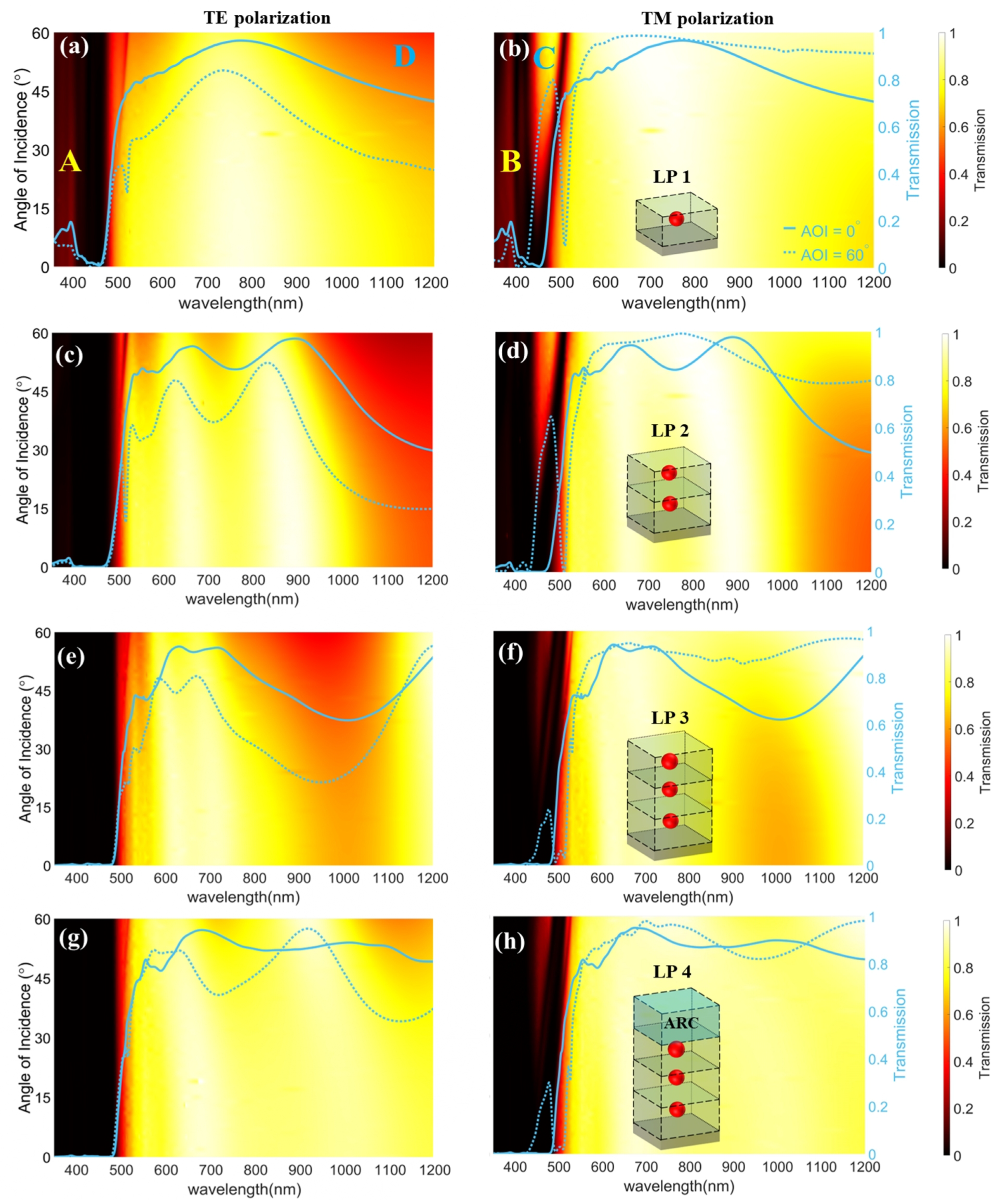
Figure 4 presents the key results on the transmission spectra contour plot for the four edge filter designs, LP1, LP2, LP3, and LP4 ( λ e d g e ~ 500 nm), based on SiNPs metamaterials under various angle of incidence (AOI), as calculated by the CST. This analysis incorporates physics such as single particle resonance modes (dipole or high-order modes), near-field interactions of neighboring particles, and periodic effects resulting from the unit cell designs [15,25]. Both TE and TM incident polarizations are considered. The designated edge wavelength of 500 nm can be adjusted by modifying the particle size and the host material, as detailed in Section 3.4 below.
LP1 design (Figure 4a,b): This single-layer design, which is akin to the study by Lotti et al. [15], incorporates a new glass substrate for practical considerations. Consequently, although the results slightly differ from those in reference [15], all of the key features remain consistent, as follows: there is a clear demonstration of edge filter behaviors and wide-angle performance, alongside poor performances in both the stop band and the pass band. In the stop band (wavelength < 480 nm), weak blocking performance occurs below 400 nm for all of the AOIs, denoted by undesired peaks in Zones A, B, and C in Figure 4a and Figure 4b, respectively. Meanwhile, in the pass band, the overall transmission in the near-infrared (IR) regime significantly attenuates as the TE-polarized AOI increases, as marked by Zone D in Figure 4a. Overcoming these challenges proves daunting, due to the single-layer design’s restricted parameter adjustability. However, the integration of the multi-layer and ARC designs furnishes additional design flexibility, effectively mitigating these issues in LP1.
LP2 design (Figure 4c,d): The implementation of the second layer ( H 1 = 255 nm) can instantly improve the blocking performance in Zones A and B, due to the greater absorption offered by an extra layer of SiNPs. The H 1 = 255 nm was determined by the parametric scanning of the CST to extend the high transmission band in the IR wavelength regime while maintaining a sharp edge, as shown in Figure S2a. The peak in Zone C can slightly suppress but is still unacceptable. Additionally, we observed a decrease in the transmitting performance in the longer wavelength (>900 nm), which can be attributed to the increased optical thickness of the host medium. This causes a mismatch between the admittance of the host medium layer and that of the air. However, we demonstrate that such undesired effects can be mitigated by incorporating an ARC, as illustrated in the final LP4 design.
LP3 design (Figure 4e,f): We implemented a three-layered design to enhance stop band blocking performance. This configuration ( H 2 = 125 nm, as depicted in Figure 1d) demonstrated significantly improved stop band blocking performance for both polarizations. The determination of H 2 = 125 nm is shown in the appendix in Figure S2b, which shows the narrow bandwidth of the peak in Zone C. For TE polarization, the stop band achieves near-perfect blocking (Figure 4e), with all wavelengths being completely blocked within the stop band under all of the AOIs, resulting in an average OD of up to 2.55. This effectively resolves the issue observed in Zone A of the LP1 design. In the case of TM polarization, the unwanted peaks in Zone B are entirely removed; moreover, while the peaks in Zone C are not fully eliminated, they still show a significant improvement compared to that of the the LP1 design. The attenuation of transmission in the longer wavelength (900–1100 nm) is still observed, due to the absence of an ARC.
LP4 design (Figure 4g,h): Building upon LP3, the LP4 design achieves further enhancement with the addition of an ARC layer. The systematic optimization of the design parameters, conducted by ESM and validated by CST, yields specific dimensions for LP3 with optimal performance ( H 0 = 133.61 nm, H 1 = 256.46 nm, H 2 = 124.77 nm, H 3 = 96.27 nm, and H 4 = 150.45 nm). LP3 demonstrates a superior overall performance, with the unwanted peaks in Zones A, B, and C being significantly reduced or eliminated, resulting in significant improvements in stop band characteristics with a max average OD = 2.55. Meanwhile, the transmission in the pass band, particularly at wavelengths of >900 nm, experiences substantial enhancement, with the average transmission exceeding 80% across the AOIs ranging from 0° to 60° for both polarizations.

3.4. Comparison of Designed Filters

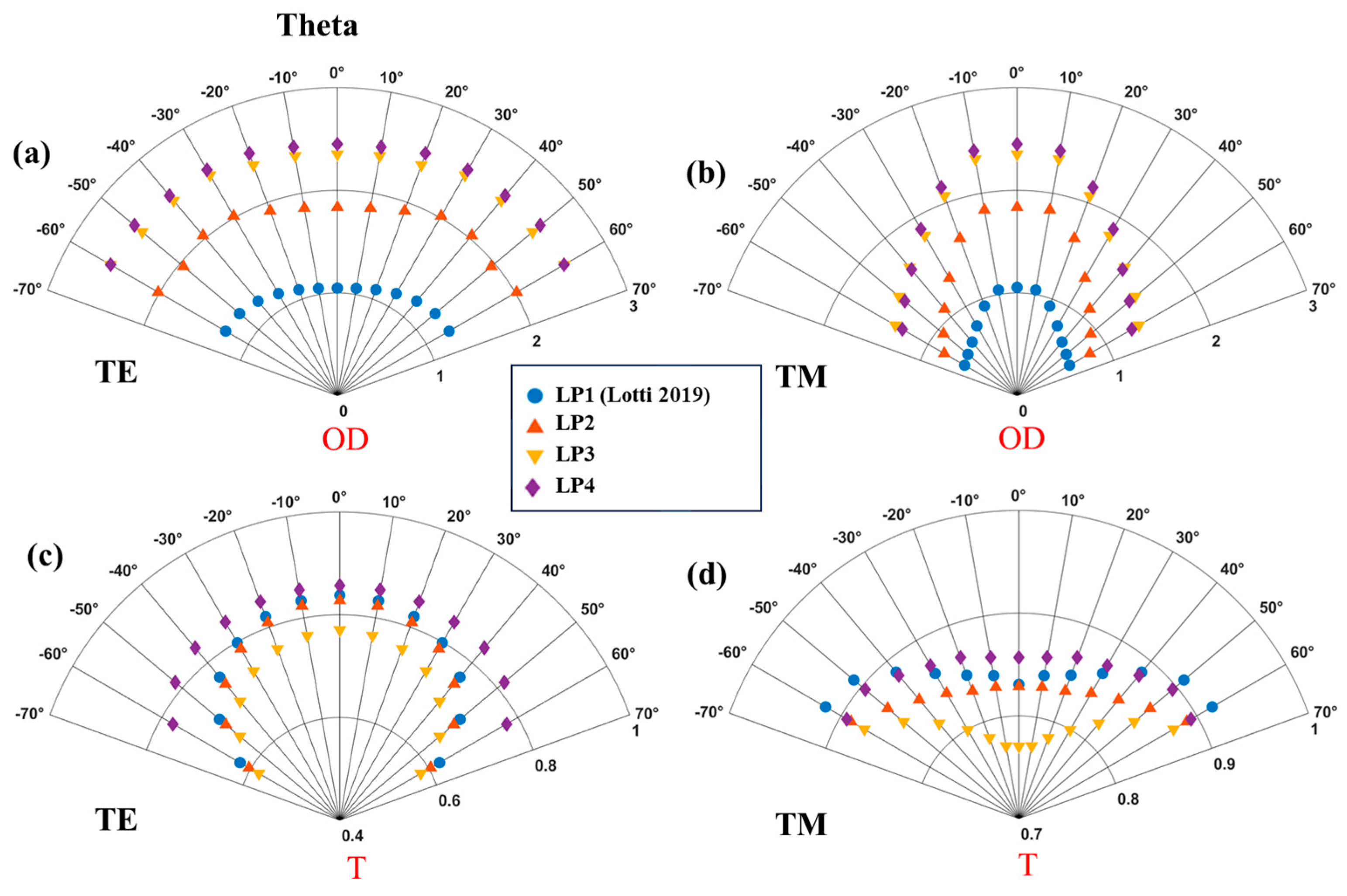
OD performance of stop band: Figure 5 illustrates a comparison of the average transmission rates for designs LP1–L4 for the stop band (350 nm–480 nm). As the number of MFLs increases, the blocking performance (OD) shows a significant improvement for both TE- and TM-polarized modes, as follows: the OD of the LP3 design increases by 1.31 compared to LP1; and by 0.52 compared to LP2 for TE polarization. In terms of TM polarization, the results exhibit less improvement, with the average OD of the LP1 design sharply decaying at high AOI, due to the presence of unwanted peaks. The OD of the LP3 design is approximately 0.71 higher than that of LP1.
The introduction of the ARC layer slightly improves the blocking performance for TE-polarized light across almost all of the AOIs, and the variation of OD for TM-polarized incidence is less than ±0.15. Importantly, our optimized design, LP4, achieves the highest reported optical density for metamaterial-based edge filters to date, as follows: OD = 2.45 (AOI = 0 ° ), OD = 2.55 (AOI =   60 ° , TE), and OD = 1.29 (AOI = 60 ° , TM), compared to the previous single-layer LP1 design with OD = 1.05 (AOI = 0 ° ), OD = 1.25 (AOI = 60 ° , TE), and OD = 0.59 (AOI = 60 ° , TM).
We also calculated the OD at an AOI of 0° for an increased number of layers. We found that the OD (AOI = 0°) approaches a maximum value that can be approximated by the following formula:
O D 12 4.6 + e x p [ 1.54 × x 2.33 ]
Here, the optical density (OD) exhibits an increasing trend with the number of layers but begins to plateau at around six layers, reaching a maximum OD of approximately 2.60. This occurs because the threshold defining the stop band is set at 10% (OD = 1) in this paper, thereby limiting the upper limit of the average OD. However, if the threshold for the stop band is reduced to 1% (OD = 1), a much higher average OD can be achieved.
As the number of MFLs grows, the average transmission of each filter with the absence of an ARC decreases for both TE- and the TM-polarized incident lights at all AOIs. This is because the total optical admittance of the MFLs and substrates mismatches the admittance of the air. The design incorporating an optimized ARC layer provides an enhancement for transmitting performance, particularly at higher AOIs, in comparison to the other three designs lacking an ARC layer. While the improvement remains relatively modest during normal incidence and low AOI, which is attributable to less reflection at a lower AOI, the improvement in transmitting performance becomes apparent as the AOI increases. The disparity in transmission between the final design and the single-layer design reaches a notable increase from 62% to 77%, at 0.15. For the TM model, the single-layer design exhibits a consistently high average transmission for all of the AOIs above 84 % . Moreover, the transmission does not experience a substantial decline, as observed in the TE incidence, when the number of MFLs is increased.
Edge shift performance: The edge shifts of all of the above designs are shown in Figure 6, showcasing the remarkable angular intolerance performance of SiNPs-based edge filters at a high TE-polarized AOI. The maximum blue shifts (AOI = 60 ° ) of the conventional edge filter are approximately 55 nm and 95 nm with TE- and TM-polarized incidences, respectively. However, the maximum edge shift of the LP1 single-layer design reaches to 9.42 nm at 60 ° . This low angular sensitivity is inherent in all multi-layered edge filters, with the final design incorporating an ARC exhibiting an even greater insensitivity across all of the AOIs. For the TM-polarized incidence, the edge shifts are much more severe than those of the TE incidence. Specifically, the red shift of the edge for the single-metalayer filter rapidly raises to 37.92 nm and the edge shift is significantly reduced by at least 50% for all of the AOIs after the introduction of multilayers of SiNP and the ARC layer.

3.5. Tunability of Edge Wavelength

While our design has a fixed edge wavelength of 500 nm, it is feasible to adjust the edge wavelength by modifying the nanoparticle size and the material to suit various application requirements. Figure 7 illustrates the particle size and the material variations that can be employed to tune the design wavelength across the entire visible spectrum. To make the results more generalizable and widely applicable, the model used for simulation is a simplified three-metalayer configuration consisting of a glass substrate and three stacked MFLs directly derived from LP1 instead of being deeply optimized, like LP3, with optimized longitudinal center-to-center distance. Crystal silicon nanoparticles enable wavelength tuning between the range of 380 and 520 nm, whereas amorphous silicon allows tuning within the 450–650 nm range.

3.6. Limitation and Future Work

We have endeavored to optimize the optical performance of the edge filter, including parameters such as optical density and transmission. Nevertheless, the refinement of the edge slope at high AOIs remains a considerable obstacle, which may constrain the filter’s utility in certain applications. For further optimization, other materials, such as graphene, plasmonic, and nonlinear materials, may be considered [26,27,28]. Furthermore, the production of large-area components constitutes an additional challenge. To this end, the self-assembly process of block copolymers (BCPs) presents a viable method for large-scale fabrication. Specifically, polystyrene-block-poly(methyl methacrylate) (PS-b-PMMA) is a promising candidate for mass production, which is attributable to its highly organized porous architecture and the adjustability of the interstitial spacing, which can be regulated to span several hundred nanometers, as reported in the literature [29]. Since BCP employs chemical-based synthesis methods, there is no significant cost increase in the multi-layer design, compared to the single-layer design, making it more suitable for mass production compared to costly lithograph-based technology [30].

4. Conclusions

Utilizing a combined design and optimization approach involving full-wave simulation and classical thin-film design methods, we have optimized wide-angle metamaterial long-pass edge filters incorporating SiNPs and an ARC. Through systematic adjustments and rigorous validation, our three-MFL design achieved a significantly higher OD compared to the original design, with enhanced transmission in TE polarization (62–77%) and higher ODs of 2.55 (AOI = 60 ° , TE) and 1.36 (AOI = 60 ° , TM). This exceptional performance renders it suitable for applications demanding consistent results across diverse angles of incidence. Moreover, the tunability of edge wavelengths enhances its adaptability to specific application requirements. Our study significantly advances the field of high-efficiency metamaterial optical components, offering an enhanced performance and versatility in various optical systems.

Supplementary Materials

The following supporting information can be downloaded at: https://www.mdpi.com/article/10.3390/photonics11050446/s1, Figure S1: The refractive indexes for (a) S i N , (b) M g F 2 , (c) crystal S i , and (d) glass substrate. Figure S2: The transmission spectra dependence of edge filter on (a) and (b), longitudinal distances, H 1 and H 2 , between two adjacent SiNSs MFLs.

Author Contributions

Conceptualization, Z.W. and B.W.; methodology, B.W., Z.W. and J.N.M.; software, B.W. and J.N.M.; validation, J.N.M. and Z.W.; writing—original draft preparation, B.W.; writing—review and editing, J.N.M., A.H. and Z.W.; supervision, Z.W. and L.Y.; project administration, Z.W., A.H. and L.Y.; funding acquisition, L.Y. and Z.W. All authors have read and agreed to the published version of the manuscript.

Funding

Leverhulme Trust Fellowship (RF-2022-659); Royal Society (IEC\R2\202040 and IEC\R2\202178).

Institutional Review Board Statement

Not applicable.

Informed Consent Statement

Not applicable.

Data Availability Statement

Data are stated in the manuscript and Supplementary Materials.

Conflicts of Interest

James N. Monks was employed by Qioptiq Ltd, St Asaph, LL17 0LL, UK. Andrew Hurst was employed by Qioptiq Ltd, St Asaph, LL17 0LL, UK. The remaining authors declare that the research was conducted in the absence of any commercial or financial relationships that could be construed as a potential conflict of interest.

References

  1. Pan, H.; Chen, X.; Xia, X. A review on the evolvement of optical-frequency filtering in photonic devices in 2016–2021. Renew. Sustain. Energy Rev. 2022, 161, 112361. [Google Scholar] [CrossRef]
  2. Silva, M.F.; Granado, T.C.; Gonnella, R.H.; Costa, J.P.C.; Assagra, Y.A.O.; Correia, J.H.; Carmo, J.P. Optical filters for narrow-band imaging on medical devices. In Proceedings of the 2017 SBMO/IEEE MTT-S International Microwave and Optoelectronics Conference (IMOC), Aguas de Lindoia, Brazil, 27–30 August 2017. [Google Scholar]
  3. Kallos, E.; Palikaras, G. Volume manufacturing and industrial applications of metamaterials: Rolling lithography, holography, laser filtering and photovoltaics. In Proceedings of the 2017 11th International Congress on Engineered Materials Platforms for Novel Wave Phenomena (Metamaterials), Marseille, France, 27 August–2 September 2017. [Google Scholar]
  4. Chang, P.; Shi, H.; Wang, Z.; Miao, J.; Shi, T.; Guo, H.; Chen, J. Cesium Faraday Optical Filter for Wireless Optical Communication System. In Proceedings of the 2021 13th International Conference on Wireless Communications and Signal Processing (WCSP), Changsha, China, 20–22 October 2021. [Google Scholar]
  5. Frey, L.; Masarotto, L.; Armand, M.; Charles, M.L.; Lartigue, O. Multispectral interference filter arrays with compensation of angular dependence or extended spectral range. Optics Express 2015, 9, 11799–11812. [Google Scholar] [CrossRef] [PubMed]
  6. Elbashar, Y.H.; Rashad, M.M.; Rayan, D.A. Protection glass eyewear against a YAG laser based on a bandpass absorption filter. Silicon 2016, 9, 111–116. [Google Scholar] [CrossRef]
  7. Ji, C.; Yang, C.; Shen, W.; Lee, K.; Zhang, Y.; Liu, X.; Guo, L.J. Decorative near-infrared transmission filters featuring high-efficiency and angular-insensitivity employing 1D photonic crystals. Nano Res. 2019, 12, 543–548. [Google Scholar] [CrossRef]
  8. Baqir, M.A.; Choudhury, P.K. Hyperbolic metamaterial-based UV absorber. IEEE Photonics Technol. Lett. 2017, 29, 1548–1551. [Google Scholar] [CrossRef]
  9. Chowdhury, M.Z.B.; Islam, M.T.; Hoque, A.; Alshammari, A.S.; Alzamil, A.; Alsaif, H.; Alshammari, B.M.; Hossain, I.; Samsuzzaman, M. Design and Parametric Analysis of a Wide-Angle and Polarization Insensitive Ultra-Broadband Metamaterial Absorber for Visible Optical Wavelength Applications. Nanomaterials 2022, 12, 4253. [Google Scholar] [CrossRef] [PubMed]
  10. Zhu, P.; Guo, L.J. High performance broadband absorber in the visible band by engineered dispersion and geometry of a metal-dielectric-metal stack. Appl. Phys. Lett. 2012, 101, 241116. [Google Scholar] [CrossRef]
  11. Soni, A.; Purohit, S.; Hegde, R.S. Multilayered aluminum plasmonic metasurfaces for ultraviolet bandpass filtering. IEEE Photonics Technol. Lett. 2017, 29, 110–113. [Google Scholar] [CrossRef]
  12. Park, J.; Hong, S.K.; Chuang, H. Numerical demonstration of angle-independent electromagnetic transparency in short-wavelength infrared regime. IEEE Access 2022, 10, 40402–40409. [Google Scholar]
  13. Wells, B.; Lotti, F.; Nasir, M.E.; Zayats, A.V.; Podolskiy, V.A. Angle-insensitive plasmonic nanorod metamaterial-based band-pass optical filters. Optics Express 2021, 29, 11562–11569. [Google Scholar] [CrossRef]
  14. Monks, J.N.; Yue, L.; Yan, B.; Aldred, B.; Hurst, A.; Wang, Z. A wide-angle shift-free metamaterial filter design for anti-laser striking application. Opt. Commun. 2018, 429, 53–59. [Google Scholar] [CrossRef]
  15. Lotti, F.; Mirzaei, A.; Wang, P.; Miroshnichenko, A.E.; Zayats, A.V. Nanoparticle-based metasurfaces for angular-independent spectral filtering applications. J. Appl. Phys. 2019, 126, 213101. [Google Scholar] [CrossRef]
  16. Estrada-Wiese, D.; Del Río, J.A. Refractive index evaluation of porous silicon using Bragg reflectors. Rev. Mex. Física 2018, 64, 72–81. [Google Scholar] [CrossRef]
  17. Hong, W.Q. Extraction of extinction coefficient of weak absorbing thin s from special absorption. J. Phys D Appl. Phys. 1989, 22, 384–1385. [Google Scholar] [CrossRef]
  18. Bertie, J.E.; Zhang, S.L. Infrared intensities of liquids. ix. the Kramers–Kronig transform, and its approximation by the finite Hilbert transform via Fast Fourier transforms. Can. J. Chem. 1992, 70, 520–531. [Google Scholar]
  19. Silva, M.F.; Pimenta, S.; Rodrigues, J.A.; Freitas, J.R.; Ghaderi, M.; Goncalves, L.M.; de Graaf, G.; Wolffenbuttel, R.F.; Correia, J.H. Magnesium fluoride as low-refractive index material for near-ultraviolet filters applied to optical sensors. Vacuum 2020, 181, 109673. [Google Scholar] [CrossRef]
  20. Luke, K.; Okawachi, Y.; Lamont, M.R.; Gaeta, A.L.; Lipson, M. Broadband mid-infrared frequency comb generation in a Si3N4 microresonator. Opt. Lett. 2015, 20, 4823–4826. [Google Scholar] [CrossRef] [PubMed]
  21. Dodge, M.J. Refractive properties of magnesium fluoride. Appl. Opt. 1984, 23, 1980–1985. [Google Scholar] [CrossRef] [PubMed]
  22. Schinke, C.; Christian Peest, P.; Schmidt, J.; Brendel, R.; Bothe, K.; Vogt, M.R.; Kröger, I.; Winter, S.; Schirmacher, A.; Lim, S.; et al. Uncertainty analysis for the coefficient of band-to-band absorption of crystalline silicon. AIP Adv. 2015, 5, 067168. [Google Scholar] [CrossRef]
  23. Vogt, M.R.; Hahn, H.; Holst, H.; Winter, M.; Schinke, C.; Köntges, M.; Brendel, R.; Altermatt, P.P. Measurement of the optical constants of soda-lime glasses in dependence of iron content, and modeling of iron-related power losses in crystalline Si solar cell modules. IEEE J. Photovolt. 2016, 6, 111–118. [Google Scholar] [CrossRef]
  24. Monks, J.N.; Williams, J.; Hurst, A.; Wang, Z. Shift-free fixed-line laser protection filter technology. In Proceedings of the SPIE 11539, Technologies for Optical Countermeasures XVII; and High-Power Lasers: Technology and Systems, Platforms, Effects IV, Online, 20 September 2020; Volume 1153908. [Google Scholar]
  25. Shilkin, D.A.; Lyubin, E.V.; Shcherbakov, M.R.; Lapine, M.; Fedyanin, A.A. Directional optical sorting of silicon nanoparticles. ACS Photonics 2017, 4, 2312–2319. [Google Scholar] [CrossRef]
  26. Li, W.; Liu, M.; Cheng, S.; Zhang, H.; Yang, W.; Yi, Z.; Zeng, Q.; Tang, B.; Ahmad, S.; Sun, T. Polarization independent tunable bandwidth absorber based on single-layer graphene. Diam. Relat. Mater. 2024, 142, 110793. [Google Scholar] [CrossRef]
  27. Luk ‘yanchuk, B.S.; Tribelsky, M.I.; Wang, Z.B.; Zhou, Y.; Hong, M.H.; Shi, L.P.; Chong, T.C. Extraordinary scattering diagram for nanoparticles near plasmon resonance frequencies. Appl. Phys. A 2007, 89, 259–264. [Google Scholar] [CrossRef]
  28. Chen, W.; Luo, Q.; Zhang, C.; Shi, J.; Deng, X.; Yue, L.; Wang, Z.; Chen, X.; Huang, S. Effects of down-conversion CeO2:Eu3+ nanophosphors in perovskite solar cells. J. Mater. Sci. Mater. Electron. 2017, 28, 11346–11357. [Google Scholar] [CrossRef]
  29. Lupi, F.F.; Giammaria, T.; Volpe, F.; Lotto, F.; Seguini, G.; Pivac, B.; Laus, M.; Perego, M. High Aspect Ratio PS-b-PMMA Block Copolymer Mask for Lithographic Applications. ACS Appl. Mater. Interfaces 2014, 6, 21389–21396. [Google Scholar] [CrossRef]
  30. Monks, J.N. Shift-free Wide-angle Metamaterial Narrowband Filters for Anti-laser Striking Applications. Ph.D. Thesis, Doctor of Philosophy, Bangor University, Bangor, UK, 2019. [Google Scholar]
Figure 1. Design schematics for edge filters: (a) A SiNP that should be embedded in the host medium. (b) Single-layered unit cell. (c) Two-layered unit cell. (d) Three-layered unit cell. (e) Three-layered unit cell with ARC.
Photonics 11 00446 g001
Figure 2. A classical edge filter exhibiting blue-shift phenomena.
Photonics 11 00446 g002
Figure 3. Comparison of transmission spectra of LP1 calculated by CST, the Bruggeman model, and the K–K model, respectively. The inset shows the refractive index derived from the K–K model and a unit cell of LP1.
Photonics 11 00446 g003
Figure 4. Transmission spectra contour plot for LP1 (a,b), LP2 (c,d), LP3 (e,f), and LP4 (g,h) designs and with TE (left column) and TM (right column) polarizations. The solid and dashed lines denote transmissions at 0° and 60° incident angles, respectively. Zones A, B, C, and D in (a,b) highlight targeted undesired peaks for elimination in subsequent designs.
Photonics 11 00446 g004
Figure 5. (a,b) The average OD for stop band (350 nm–480 nm) and (c,d) average transmission for pass band (500 nm–1200 nm) of 4 edge filters under different AOIs (represented as Theta) and with both TE (left) and TM (right) polarized incidence. The LP1 (Lotti+2019) design is from Ref. [15].
Photonics 11 00446 g005
Figure 6. The shift of edge wavelength of LP0–4 with TE- (a) and TM- (b) polarized AOI. The LP1 (Lotti + 2019) design is from Ref. [15].
Photonics 11 00446 g006
Figure 7. Tunability of edge wavelength range (highlighted by the green arrows) in the three-metalayer configuration based on three stacked MFLs from LP1 by varying silicon nanoparticle size and applying (a) crystal and (b) amorphous silicon.
Photonics 11 00446 g007
Table 1. The configuration of 5 long-pass (LP) edge filters used in this paper. LP1-LP4 are metamaterial-based edge filters, and their corresponding unit cell figures are listed in the brackets.
Design IDLong-Pass (LP) Edge Filter
(H: High-index material layer with quarter-wavelength thickness, L: Low-index material layer with quarter-wavelength thickness, and the reference wavelength is 445 nm)
( M :   meta-layer ,   ARC :   M g F 2 used as anti-reflection coating)
LP0 A i r 0.8 ( 0.5 H   L   0.5 H ) 12 G l a s s
LP1 A i r M G l a s s (Figure 1b)
LP2 A i r ( M ) 2 G l a s s (Figure 1c)
LP3 A i r ( M ) 3 G l a s s (Figure 1d)
LP4 A i r A R C | ( M ) 3 G l a s s (Figure 1e)
Disclaimer/Publisher’s Note: The statements, opinions and data contained in all publications are solely those of the individual author(s) and contributor(s) and not of MDPI and/or the editor(s). MDPI and/or the editor(s) disclaim responsibility for any injury to people or property resulting from any ideas, methods, instructions or products referred to in the content.