Article

Interference Mitigation in VLC Systems using a Variable Focus Liquid Lens

Department of Electrical and Computer Systems Engineering, Monash University, Melbourne, VIC 3800, Australia
*
Author to whom correspondence should be addressed.
Photonics 2024, 11(6), 506; https://doi.org/10.3390/photonics11060506
Submission received: 1 May 2024 / Revised: 22 May 2024 / Accepted: 24 May 2024 / Published: 26 May 2024
(This article belongs to the Special Issue Advanced Technologies in Optical Wireless Communications)

Abstract

:
The field of view (FOV) is an important parameter of a visible light communication (VLC) receiver. A variable FOV can be useful to mitigate interference from neighboring cells in a multi-cell VLC network. The existing works on dynamic FOV VLC receivers have used a mechanical iris to control the receiver’s FOV, making the VLC receiver bulky, slow, and power-consuming. In this article, an electronically controlled variable focus liquid lens is used to vary the FOV of the receiver dynamically. A low-cost microcontroller-based feedback control system controls the effective FOV of the receiver to reject signals from unwanted transmitters, thus maximizing the signal-to-interference plus noise ratio (SINR) of the received signal. Experimental results show that the proposed technique effectively improves SINR performance in a multi-cell VLC network. To the best of the authors’ knowledge, this is the first reported work to utilize an electronically controlled compact liquid lens for designing a dynamic FOV VLC receiver.

1. Introduction

Visible light communication (VLC) is an emerging wireless communication technology that utilizes visible light as a data carrier. VLC can complement future wireless communication systems to address the spectrum crunch caused by the exponential growth of data traffic [1,2,3]. Researchers have already achieved speed in the order of gigabits/s in VLC systems [4,5,6,7,8]. However, one of the major drawbacks of VLC systems is their small coverage and short range [8]. Multiple VLC transmitters are generally used to cover an entire area due to the small communication coverage and line-of-sight nature of VLC systems. In fact, this brings the advantage of high spatial density in VLC systems compared to radio frequency communication systems. One of the key factors affecting multi-cell VLC systems’ performance is the receiver’s field of view (FOV) [9]. FOV refers to the angle of visibility between the transmitter and receiver from the receiver’s point of view. FOV is a crucial parameter in VLC systems as it determines the number of transmitters ’seen’ by the receiver and the amount of light received by the receiver. A smaller FOV leads to a higher outage probability. A larger FOV, on the other hand, increases the likelihood of interference from nearby unwanted light sources, including neighboring VLC transmitters, which can degrade the signal quality and reduce the data transmission rate. Therefore, there is a trade-off between the outage probability and the data transmission rate. The issue becomes more serious in dense VLC transmitter deployment scenarios. Therefore, the FOV must be carefully considered when designing VLC systems to ensure optimal performance. The importance of receiver FOV in VLC is depicted in Figure 1.
To reduce unintended interference from neighboring transmitters in a multi-cell VLC architecture, different optimization techniques are used at the transmitter end, including optimization of individual transmitter’s time-scheduling, power allocation, and zero-forcing precoding [10,11]. These techniques are sensitive to users’ density and locations [11]. At the receiver end, angular diversity receivers, proposed to mitigate interference are non-planar and bulky [12,13,14,15,16]. The polarization of the optical signal has been exploited to mitigate interference of unwanted signals [17]. A liquid crystal device (LCD) has been used in front of the photo-diode (PD) to block signals from unwanted directions and improve interference performance [18]. The optimization of the receiver’s field of view has also been proposed [11]. Using simulation results, it has been shown that communication performance can be improved significantly using a dynamic field-of-view receiver [9,19,20]. For hardware-level implementation, a mechanical iris has been used to dynamically change the receiver’s field of view to improve communication performance in dense multi-cell VLC networks [21]. A mechanical iris commonly found in digital cameras is a mechanical system where the FOV of the sensor can be changed mechanically according to the need. In VLC systems, the optimum FOV is mainly determined by the position of the receiver with respect to different transmitters. A larger iris opening leading to a larger FOV allows more signal to be detected by the receiver and a smaller iris opening leads to minimum interference from neighboring cells. A particle swarm optimization of the receiver’s FOV has been proposed using a similar mechanical setup [11]. However, a motor-controlled mechanical iris is bulky, slow, and power-consuming, thus impractical for communication systems, especially for compact handheld electronic devices. A non-mechanical, compact system is necessary for the VLC receiver’s front end. In this paper, a variable focus liquid lens is utilized to adapt the FOV of the high-speed VLC receiver to minimize inter-cell interference of a VLC network and to maximize the signal-to-interference plus noise ratio (SINR) of the received signal.
The rest of the paper is organized as follows: Section 2 presents the simulation results, Section 3 explains the working principle of the proposed receiver, Section 4 describes the experiment process and discusses the experimental results, Section 5 discusses the advantages and potential application scenarios of the proposed system, and finally, in Section 6, conclusions are drawn.

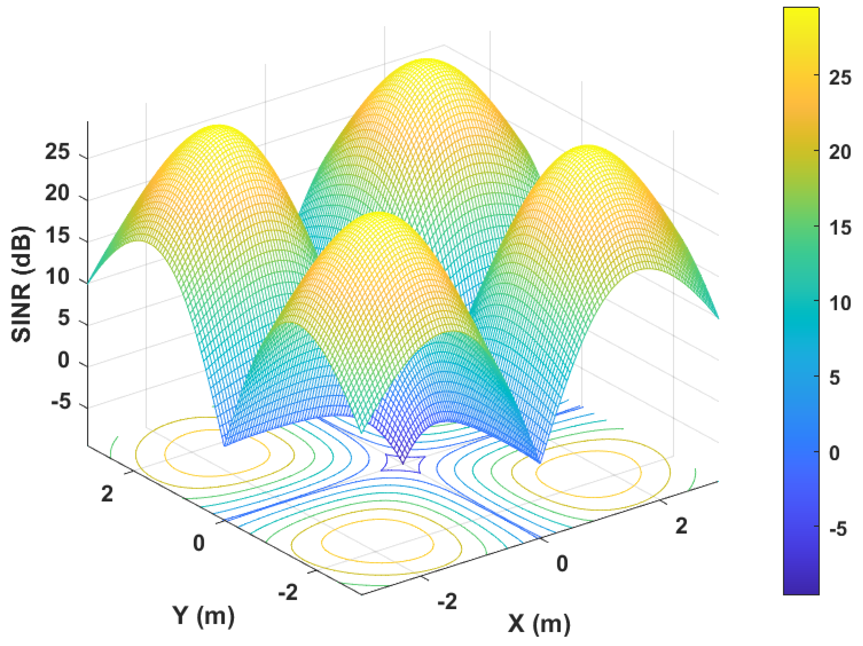
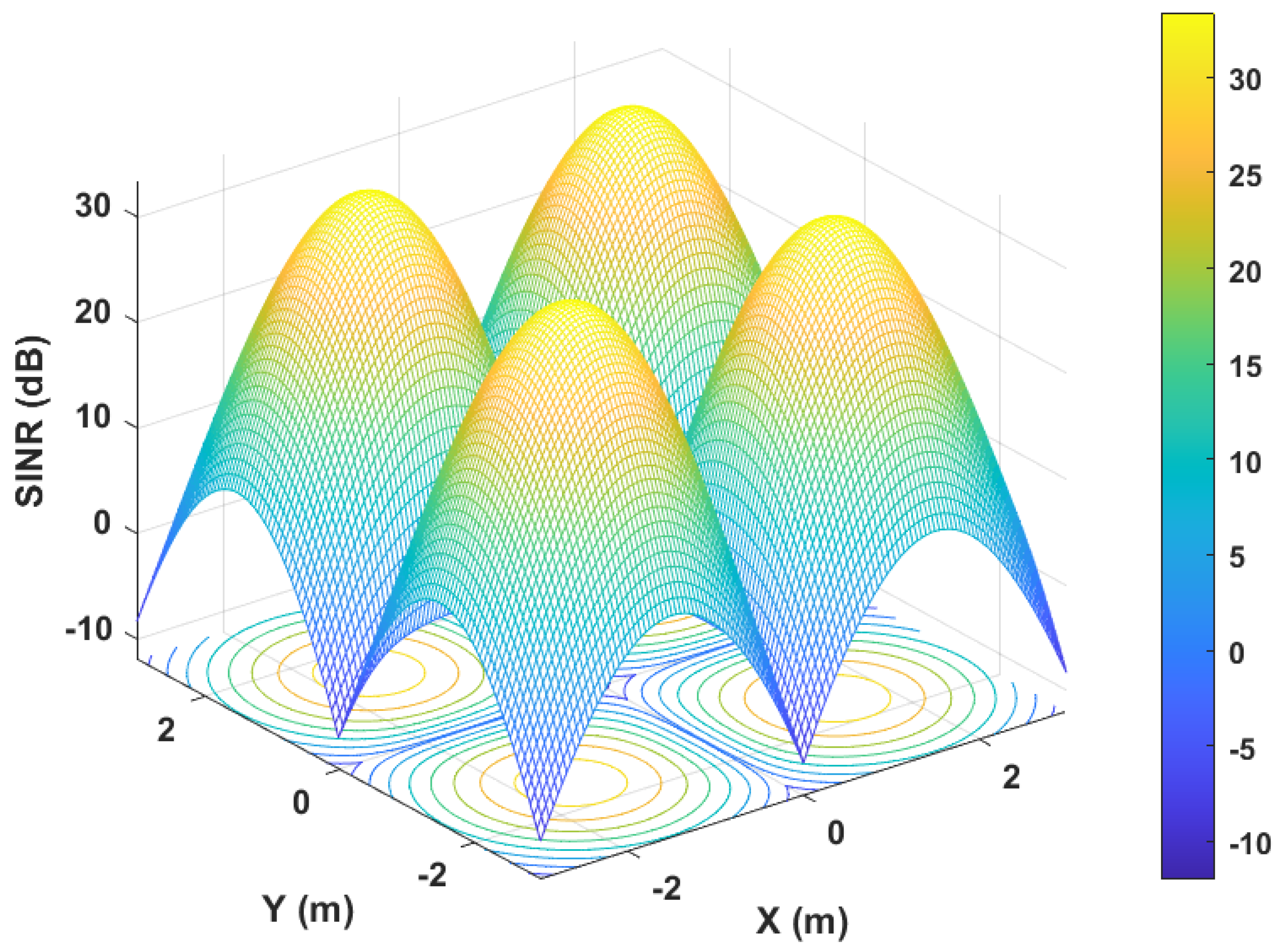
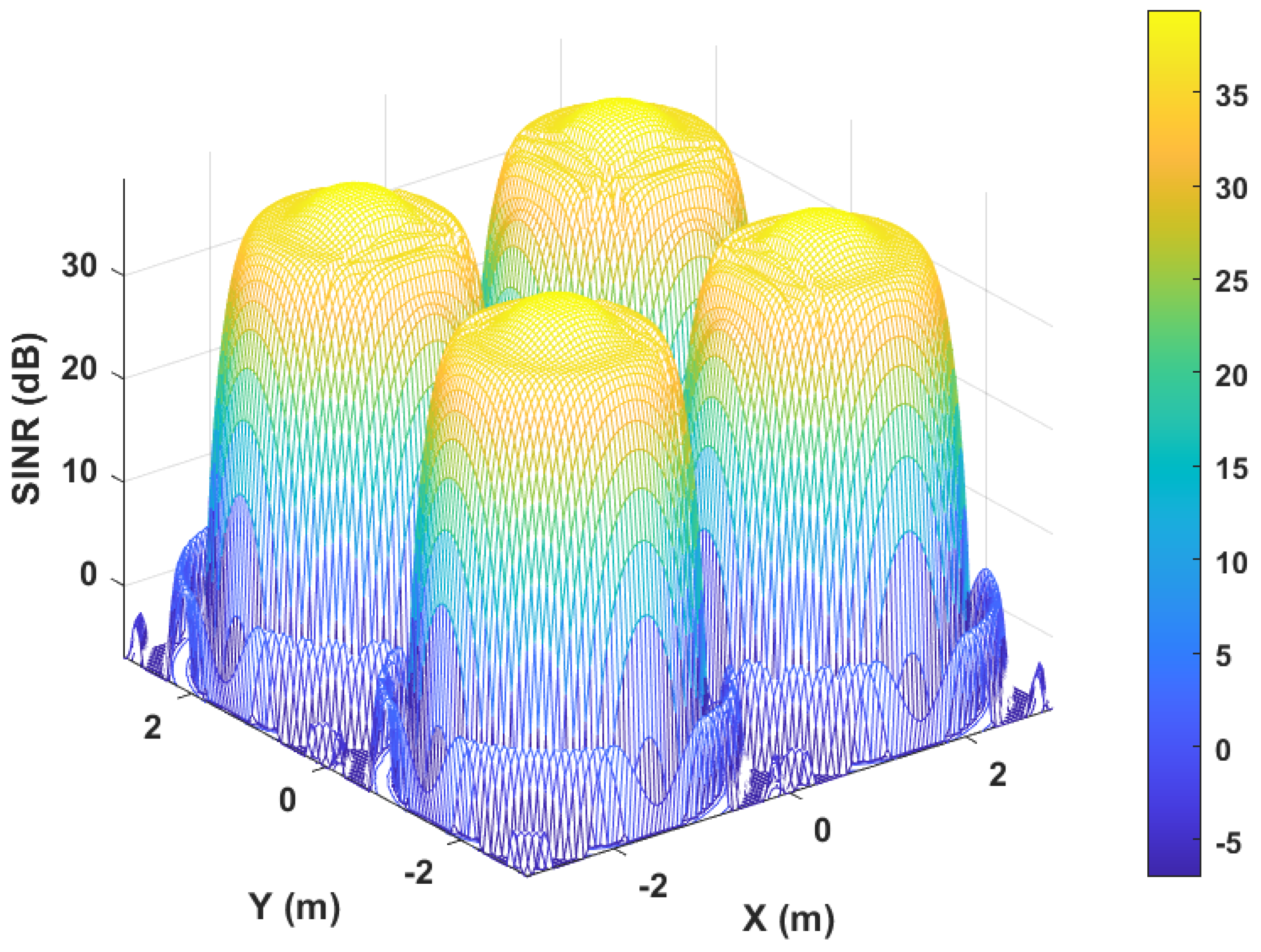
2. Simulation Results

To study the effect of the receiver’s FOV on communication performance, a multi-cell VLC system is simulated in MATLAB®. An LED or a diffused laser diode (LD) can be considered a Lambertian source, with an optical beam distribution as expressed below:
R ( ϕ ) = ( m l + 1 ) 2 π c o s m l ( ϕ ) , if π / 2 ϕ π / 2 0 , elsewhere ,
where ϕ and ψ are irradiance and incidence angles, respectively. m l = l n 2 l n ( c o s Φ 1 / 2 ) is the Lambertian emission order, which is a function of the half-power semi-angle of the transmitter, Φ 1 / 2 .
The line-of-sight channel gain can be expressed as:
H l o s = A r c o s ( ψ ) ( m l + 1 ) 2 π d 2 c o s m l ( ϕ ) G l e n s , if 0 ψ ψ m a x 0 , elsewhere ,
where G l e n s is the gain of the receiver lens; A r is the area of PD; and d is the Euclidean distance between the transmitter and PD. In a room with multiple transmitters, the SINR can be expressed as:
S I N R = ( R p d H l o s P t , α ) 2 ( B w × I N C ) 2 + i α ( R p d H i P t , i ) 2 ,
where R p d ( A / W ) is the detector responsivity; B w ( H z ) is the bandwidth of the VLC channel; I N C ( A / H z ) denotes the input noise current of the PD.
A standard room size (5 m × 5 m × 3 m) has been chosen. The transmitter power, detector diameter, responsivity of PD, bandwidth of the system, and input noise current are 10 W, 0.4 mm, 0.2 A/W, 20 MHz and 16 pA/ Hz respectively. The half-power beam width of each transmitter has been taken as 60 to simulate the lighting-grade LEDs. The receiver is assumed to always face the roof perpendicularly, and the receiver plane is at a height of 0.85 m above the floor. The signal from each transmitter is degraded by the interference caused by the other three transmitters. The simulation result for the receiver’s FOV of 45 is shown in Figure 2. The maximum SINR is achieved when the receiver is just under the individual transmitters. The maximum simulated SINR for this case is 27 dB. The simulation result for the receiver’s FOV of 30 is shown in Figure 3. It is found that the peak SINR has improved by 6 dB compared to the previous case. However, due to reduced FOV, the performance degrades when the receiver moves away from the transmitter. As a result, the minimum SINR has dropped from −5 dB to −12 dB. The negative SINR indicates that the interference from neighboring transmitters is greater than the desired received signal. The drop in the minimum SINR means that the outage probability of the communication system increases with a lower FOV of the receiver. The trade-off between communication performance and FOV is very critical for VLC systems.
Next, the multi-cell VLC system is simulated with a variable FOV. All the other simulation parameters remain the same except the FOV of the receiver. It is assumed that the receiver’s FOV is dynamic and it can be adjusted with a resolution of 1 to maximize the SINR performance. At each receiver position, the FOV is varied 0 to 90 with a resolution of 1 , and the FOV corresponding to the maximum attainable SINR at that point is considered as ideal. The simulation result for this case is shown in Figure 4. The maximum and the average SINR have improved to 39.3 dB and 17.6 dB, respectively.
Therefore, theoretically, it is established that a dynamic FOV of the VLC receiver can reduce the inter-cell interference, thus improving the overall throughput of the multi-cell VLC network. In this paper, a variable-focus liquid lens is utilized to implement the dynamic FOV of the high-speed VLC receiver to minimize the inter-cell interference of a VLC network and to maximize the SINR of the received signal. The experimental details and results are presented in the next sections.

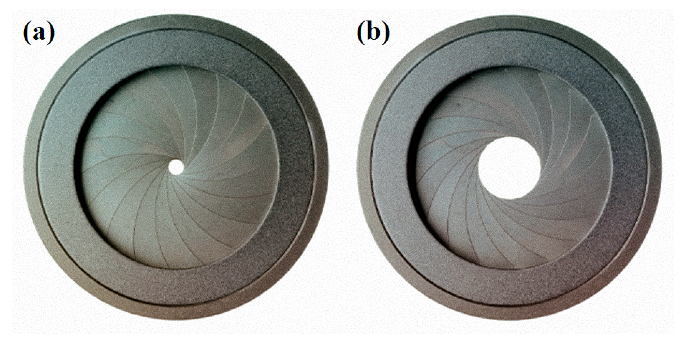
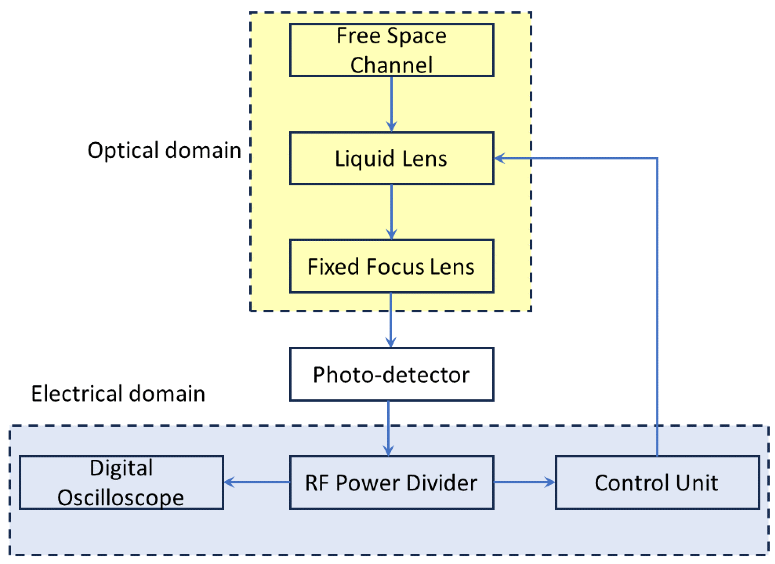
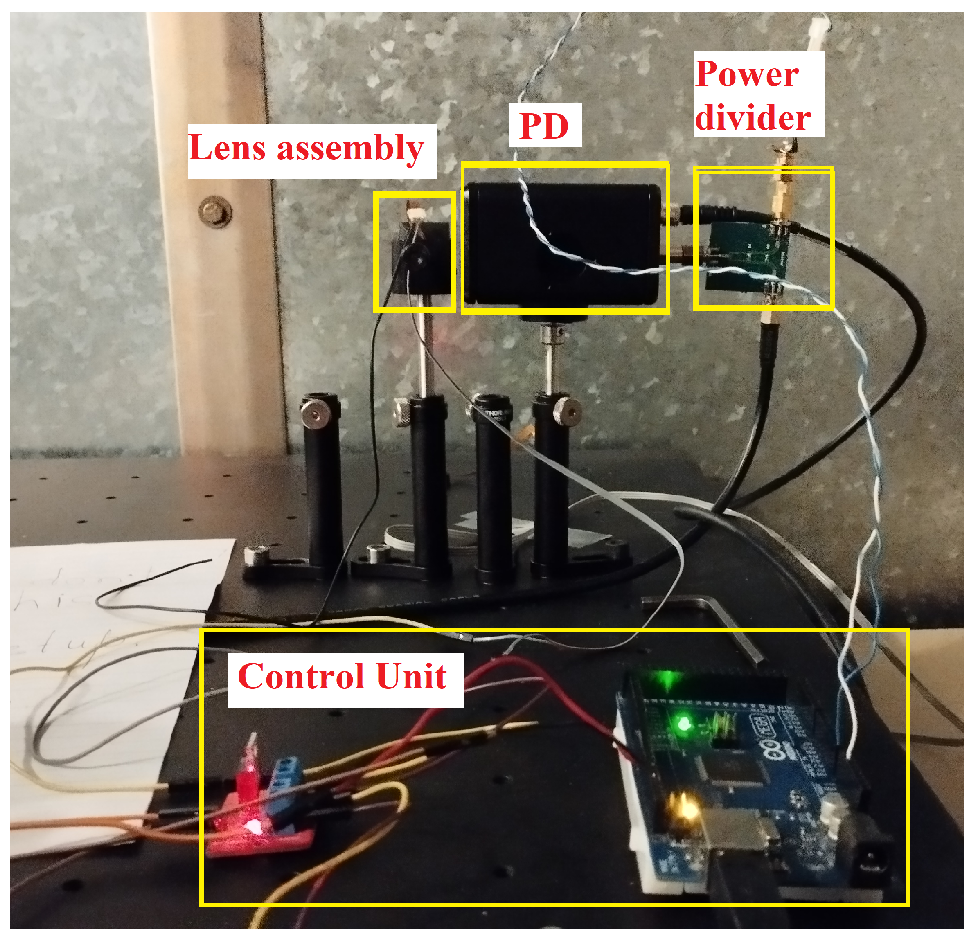
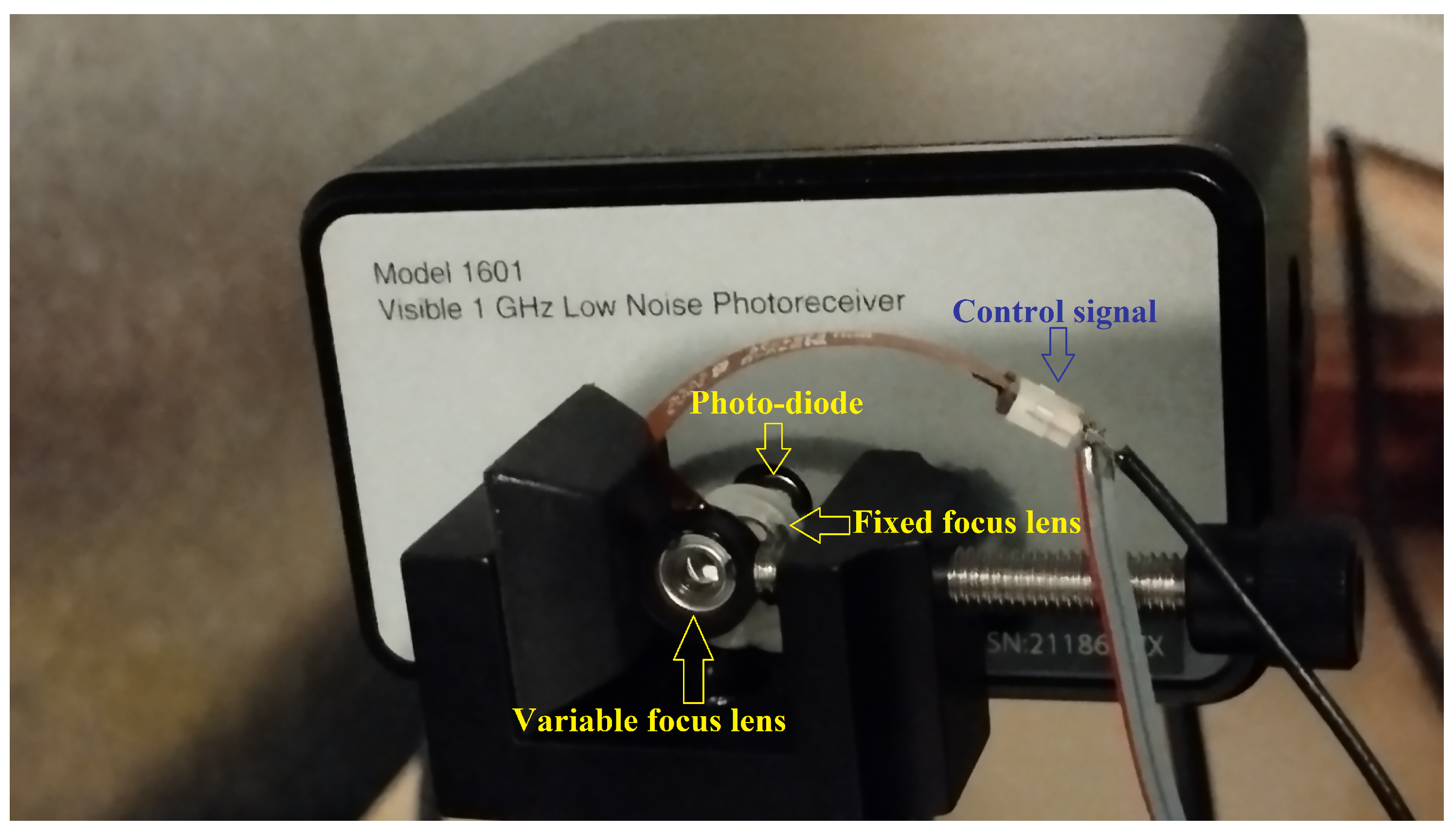
3. System Description

The goal of this work is to optimize the receiver FOV at the hardware level at the receiver front end. The intention is to receive the transmitted signal from one transmitter at the minimum FOV of the receiver. A mechanical iris-based dynamic FOV receiver has been proposed in the literature [19,21], as shown in Figure 5. In this work, it is implemented using a dynamic FOV lens assembly. The lens assembly consists of two lenses: one variable-focus liquid lens and the other, a fixed focus lens, as shown in Figure 6. The liquid lens (Corning variable-focus lens A-25H0-D0-P10) has an electronically variable focal length starting from −28 mm to +28 mm. The basic structure of a liquid lens consists of a small chamber filled with a conductive liquid, typically water or oil, and separated from the surrounding environment by a hydrophobic (water-repellent) coating. The liquid is typically contained within a transparent glass or plastic membrane. The key principle behind the operation of a liquid lens is electrowetting. Electrowetting refers to the phenomenon where the wetting properties of a liquid on a solid surface can be modified by applying an electric field. In the case of a liquid lens, an electric voltage is applied across electrodes placed on either side of the liquid chamber. By varying the voltage across the electrodes, the curvature of the liquid droplet can be controlled, thereby changing the focal length of the lens. The fixed-focus aspheric lens (Thorlabs ACL1210U) has a focal length of 10.5 mm. The optical signal enters the liquid lens from the free space channel and then passes through the fixed focus lens. Finally, the optical signal is received by the high-speed photo-detector (New Focus 1601FS-AC). The focal length of the liquid lens is varied electronically using a control signal. Thus, the effective focal length of the lens assembly can be expressed [22] according to Equation (4).
1 f e f f = 1 f l i q u i d + 1 f f i x e d + d f l i q u i d · f f i x e d
where f e f f is the effective focal length of the lens assembly, f l i q u i d is the focal length of the liquid lens, f f i x e d is the focal length of the fixed aspheric lens and d is the distance between the liquid lens and the aspheric lens, as shown in Figure 6. The distance (d) between the liquid lens and the fixed focus lens is kept at 3 mm. It is kept at the minimum possible distance in the setup to minimize non-linearity in the control signal. The relationship between a lens’ focal length and its field of view is inversely proportional. In general, as the focal length of a lens increases, the field of view decreases, and vice versa. It can be varied according to Equation (5). Thus, the FOV of the lens assembly can be electronically varied.
F O V e f f = 2 tan 1 S 2 f e f f
where S is the size of the sensor, in this case, the diameter of the photo-diode. By varying the control voltage of the liquid lens from 31 V to 64 V, the effective FOV of the lens assembly can be varied from 6.1 to 16.5 , as shown in Figure 7, and it can be seen that the relationship is practically linear.
The block diagram of the proposed variable FOV VLC receiver is shown in Figure 8. The transmitted signals enter the receiver from the free-space channel through the liquid lens. After passing through the liquid lens, the light passes through the fixed focus aspheric lens and is collected by the photo-detector. The combination of these two lenses develops an overall lens assembly with a controllable FOV. The photo-detector converts the optical signal into an electrical signal. The output of the photo-detector module is passed through a broadband power divider designed and fabricated in-house. One output of the power divider goes to a digital oscilloscope for monitoring and the other output is connected to a control unit. The control unit processes the signal and provides a control signal to the liquid lens so that the FOV of the lens assembly can be optimized for minimum interference from neighboring transmitters. In this system, two laser diodes have been used as two transmitters. Both transmitters are blue laser diodes transmitting the same wavelength (450 nm) of light and the same optical power. Both transmitters send different on–off-keying (OOK) modulated signals sampled at a maximum of 1700 M Samples/s. One transmitter acts as a noise source for the other transmitter. The control unit is implemented using a low-cost Arduino Atmega 2560 microcontroller together with an IRF520N power MOSFET module. The control unit detects both the OOK and the noise signal. If the interference from the noise signal is high then the control unit sends a pulse-width-modulated signal to the MOSFET module. The output of the power MOSFET module adjusts the focal length of the liquid lens so that only the desired signal is detected by the photo-diode and the interfering light goes out of the FOV of the photo-diode receiver.
Each frame of the transmitted signals from both transmitters consists of two parts: (a) a unique identifier and (b) an actual modulated signal, as shown in Figure 9. The unique identifier is a 10-bit sequence code and is different for two transmitters. The transmitters are synchronized and the two identifier bit sequences from the two corresponding transmitters are transmitted in time division multiplexed form. At the receiver side, the control unit detects the identifier bit sequence to understand which signal is being received. The algorithm running in the control unit is presented through a flow chart in Figure 10. If the control unit cannot detect any identifier bit sequence, it sends a control signal to the liquid lens to increase the FOV of the receiver. If the control unit detects identifier bit sequences from both transmitters, it indicates that the receiver FOV is larger than necessary. It then sends a lower control voltage to the IRF520N power MOSFET module to reduce the FOV. Conversely, if the control unit identifies only one identifier bit sequence, then it indicates that the receiver is receiving a signal from only one transmitter. In that case, there is no interference from neighboring transmitters. Therefore, no FOV modification is required. For more than two transmitters, the number of identifier sequences needs to be increased. As the length of the identifier bit sequence is significantly smaller compared to the actual OOK signal, this does not degrade the communication speed.

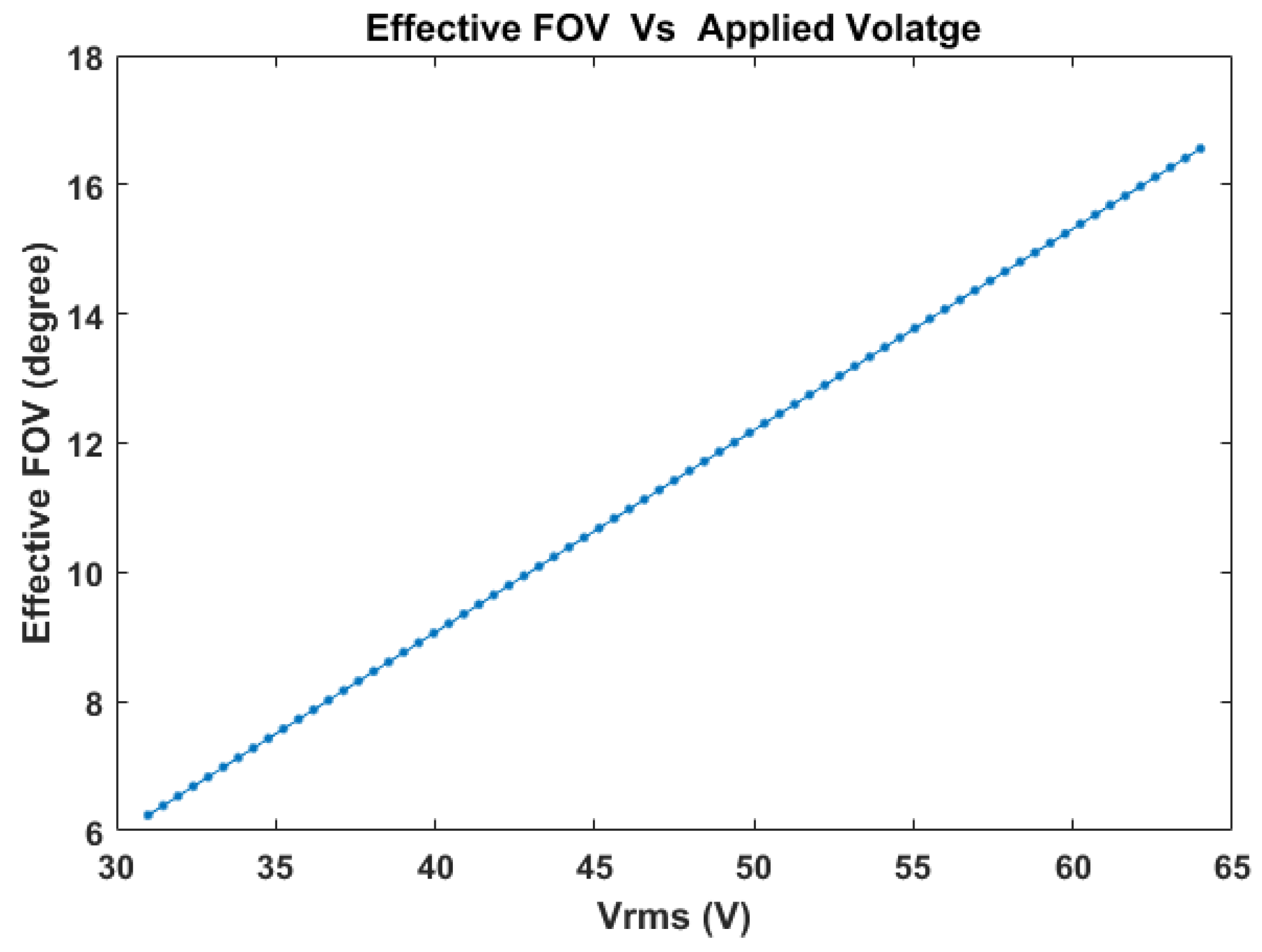
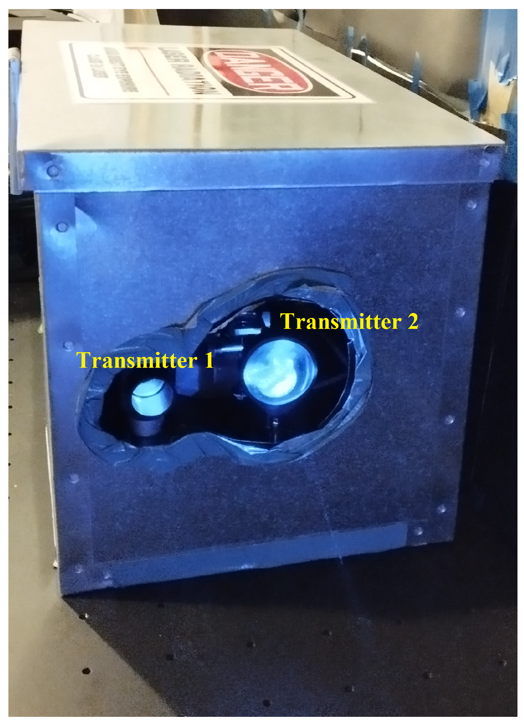
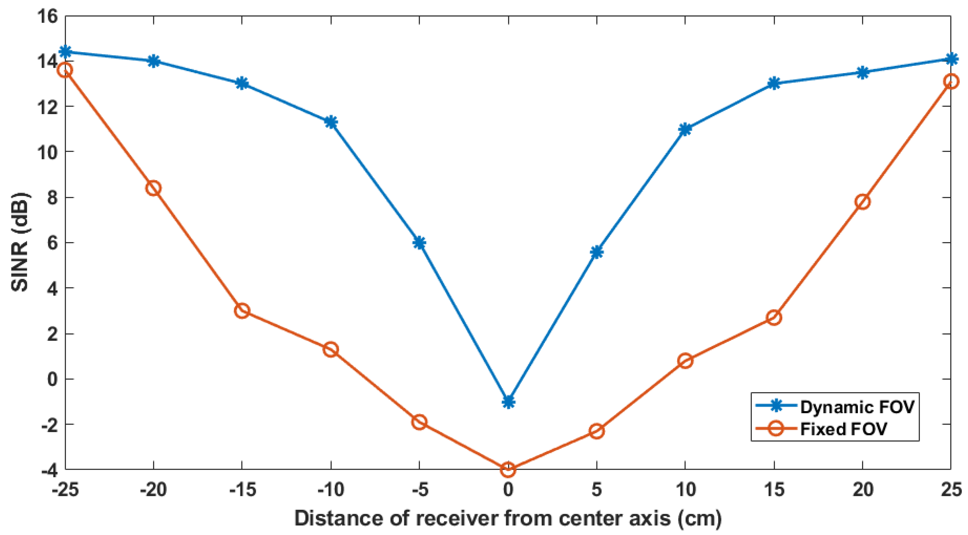
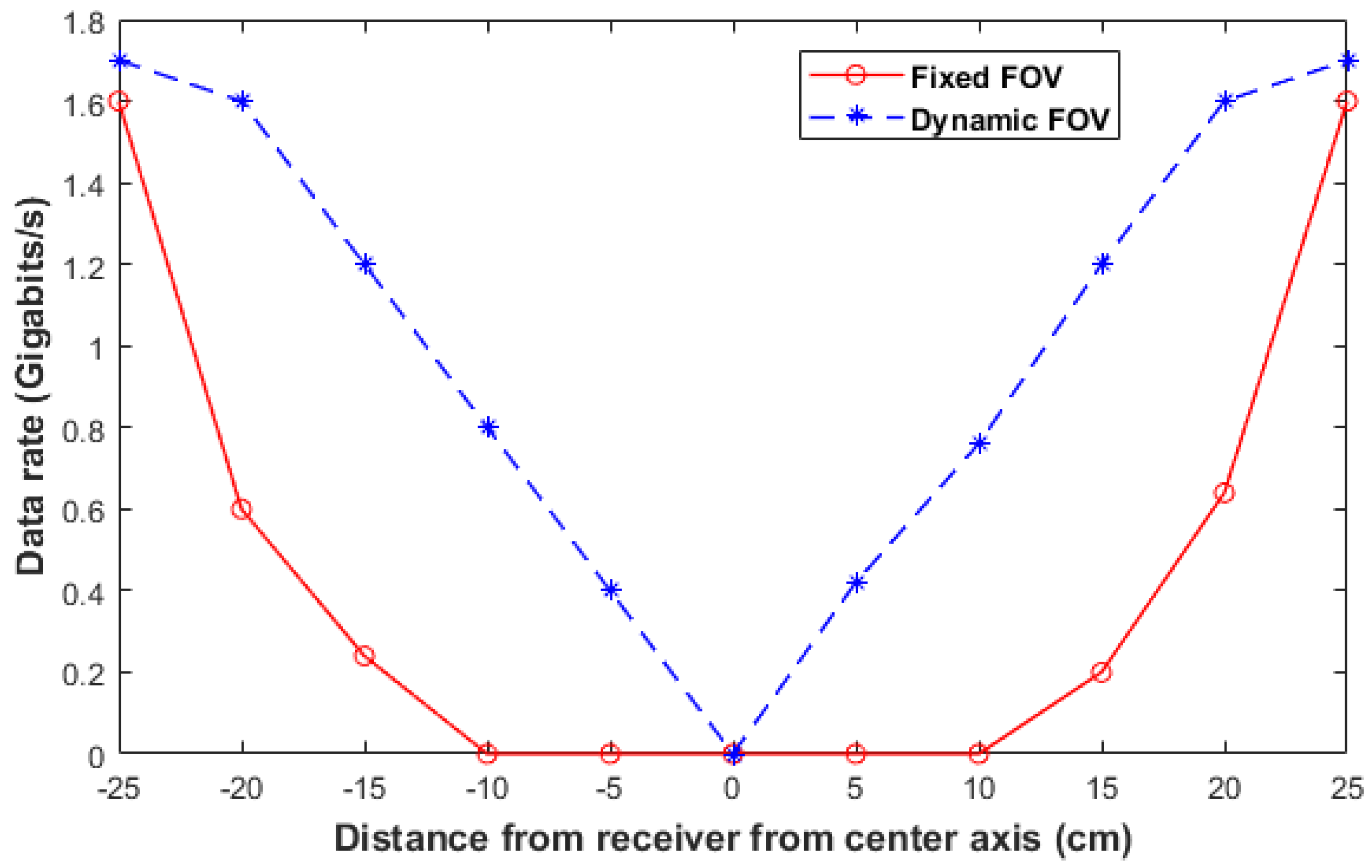
4. Experiments and Results

The experiments were performed in the laboratory with the optical components placed on an optical table for proper alignment. Two 450 nm blue laser diodes (Thorlabs PL450B) are used as transmitters: one acting as a desired transmitter and the other as an interfering signal source. The transmitter laser outputs are diffused and then directed towards the receiver, as shown in Figure 11.
The receiver side of the setup is shown in Figure 12 with the main blocks marked. The lens assembly is shown in detail in Figure 13. The distance between the transmitter and the receiver is 1.25 m. The two transmitters were placed with varying distances between them, starting from 5 cm up to 50 cm. For each position, the system performance was evaluated in terms of received SINR. It was found that the receiver can mitigate the interference with two transmitters at as close proximity as 10 cm. In practical scenarios, however, indoor lights are not installed so closely. Therefore, the performance evaluation of the proposed system was performed for the two transmitters placed at a 50 cm distance while keeping practical scenarios in mind. The SINR performance of a fixed FOV lens and our proposed dynamic FOV lens assembly are compared.
The SINR is calculated by measuring the received desired signal power, the interfering signal power, and the system noise power by turning off each transmitter at a time at each position of taking the reading. On the optical table, the receiver’s position was kept fixed because the manual alignment of the lens assembly and the photo-detector is difficult and time-consuming, and it is easier to change the positions of the transmitters. One at a time, two LD transmitters were placed at a distance of 50 cm along the perpendicular axis of the communication direction. The two LD transmitter’s positions were shifted, with one transmitter’s position starting from 0 cm up to 50 cm at 5 cm intervals without changing the distance between them. The receiver considers the nearer transmitter as the desired one and the further one as interference. This method was adopted to replicate the situation as if the transmitters are at fixed positions and the receiver is moving, as happens in practical scenarios. The distance between the two transmitters was kept at 50 cm as practical indoor lights are generally not installed at any closer intervals than 50 cm. Effectively, the measured SINR at different receiver positions is plotted in Figure 14 for both the dynamic FOV receiver and fixed FOV receiver. It can be seen that the dynamic FOV receiver performs better at all positions, and the improvement is more significant when the receiver is nearer the middle of both transmitters. On average, the SINR improvement is more than 8 dB. The improvements are less significant when the receiver is either at the edge or in the middle of the two transmitters. At the edges, the interference is already insignificant, thus the improvement is minimal. In the middle, the interference is too severe to be mitigated. Apart from these two extreme positions, the SINR improvements are significant. Thus, a dynamic FOV receiver can be useful for interference mitigation in multi-cell VLC networks, especially in dense deployments. As the lenses and the PD are all circular and thus symmetrical, the one-dimensional receiver position shifting is enough to validate the effectiveness of the proposed system.

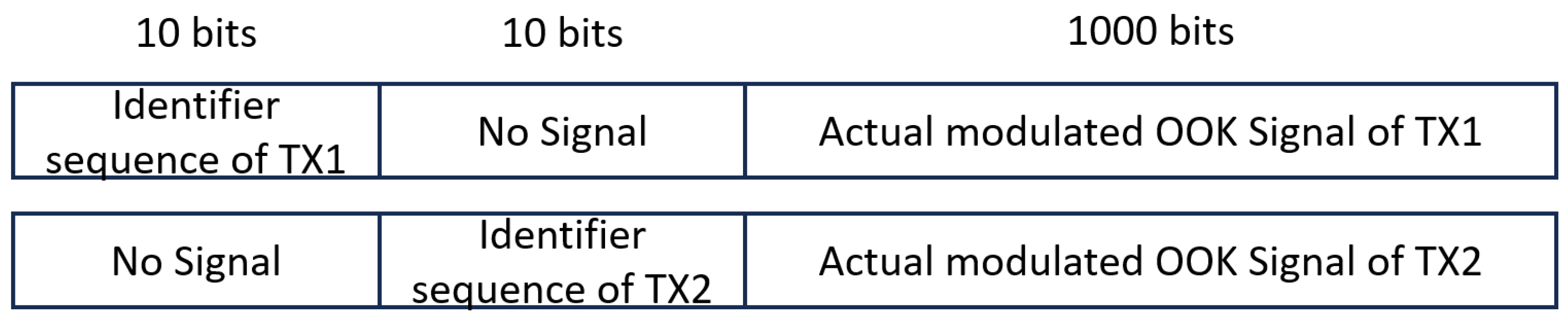
Communication Performance

The communication performance at each point is evaluated and shown in Figure 15. For a fair evaluation, the maximum possible error-free data rate has been considered. The OOK modulation scheme was used for its simplicity. The sampling rate is varied and the maximum possible sample rate with no bit error is 1700 MHz, corresponding to a 1700 Mbps data rate, ignoring the identifier sequence. When the receiver was moved away from the transmitter, the interference increased. Thus, the data rate degrades gradually. However, the data rate fell sharply when the FOV of the receiver was fixed. On the other hand, for liquid lens-based dynamic FOV, the data rate was more stable. Except for exactly in the middle of the two transmitters, the data rate is higher than 400 Mbps. At all points, the dynamic FOV receiver performs better.

5. Discussion and Potential Applications

In the literature, most works [12,13,14,15,16] have used angular diversity receivers to reduce interference in a VLC network. These receivers are non-planar and they consume more power due to multiple PDs involved. Mechanical iris-based dynamic FOV receivers [11,19,21] can mitigate interference using a single PD. However, they are bulky and more power-consuming (a few hundred mW) due to their mechanical operation and the involvement of an additional mechanical motor. Mechanical iris can also be noisy, which is not desired. The liquid lens-based receiver proposed in this paper is electronically controllable, compact (2.8mm thickness), silent, and less power-consuming (14 mW to be precise). As a result, the proposed receiver can be more suitable for hand-held devices. A comparison between this work and the related literature is presented in Table 1.
The maximum power consumption of the liquid lens is 14 mW. There is no measurable power loss for the liquid lens compared to a solid glass-based lens. The power divider is a 10:90 divider. Therefore, only 10% of the received signal is used to control the liquid lens. The remaining 90% of the signal is processed for calculating the SINR. Therefore, the noise added by the passive power divider circuit is included in the measured SINR.
The method will work irrespective of LED or LD. The size of the light source should be smaller for better performance. The proposed method is more suitable for high-speed VLC systems where the transmitters are generally laser diodes (smaller size even after including the diffuser).
In indoor conditions, this proposed system can reduce interference without the risk of a signal outage. For PD-based receivers, photo-diode saturation is another issue that degrades the received signal quality in outdoor conditions. Within the photo-diode FOV, if there is any unwanted bright light source, such as the Sun or headlights from other cars, then the photo-diode becomes saturated. Optical filters, to some extent, can prevent saturation by blocking unwanted wavelengths of incident light but they degrade the signal power too. A variable FOV using a variable focus lens at the receiver can help avoid PD saturation by dynamically adjusting the FOV depending on the outdoor conditions.
Dynamic FOV receivers can also be very useful for visible light positioning systems. One of the issues of VLP systems is the small field of view VLC receivers and the requirement of dense lighting installation because of that. A wide FOV receiver, on the other hand, is affected by higher short noise, more interference, and distorted images in the case of image sensor receivers. A wide FOV lens for an image sensor may not be perfect for a front-faced camera in a smartphone with the primary purpose of photography. A variable FOV receiver can adjust the FOV depending on the channel conditions and application scenario.

6. Conclusions

The FOV of a receiver is a critical parameter in a multi-cell VLC system. An electronically controlled variable FOV receiver can be a solution for maintaining an LOS connection with the strongest signal intensity as well as reducing interference from unwanted sources. In this work, an electronically controllable variable focus liquid lens is utilized to design a dynamic FOV VLC receiver for mitigating interference from neighboring cells. Experimental results show that the proposed dynamic FOV receiver significantly improves the SINR compared to a fixed FOV receiver. The proposed solution is compact, faster, and consumes less power compared to existing mechanical iris-based solutions. In addition to multi-cell VLC systems, the proposed solution has potential applications in indoor positioning and intelligent transport systems.

Author Contributions

Conceptualization, K.B.; methodology, K.B.; software, K.B.; validation, K.B.; investigation, K.B.; resources, N.K.; writing—original draft, K.B.; writing—review and editing, N.K.; supervision, N.K.; project administration, N.K. All authors have read and agreed to the published version of the manuscript.

Funding

This research received no external funding.

Institutional Review Board Statement

Not applicable.

Informed Consent Statement

Not applicable.

Data Availability Statement

Data presented in this paper are available upon request. The request should be made through email.

Conflicts of Interest

The authors declare no conflicts of interest.

References

  1. Burchardt, H.; Serafimovski, N.; Tsonev, D.; Videv, S.; Haas, H. VLC: Beyond point-to-point communication. IEEE Commun. Mag. 2014, 52, 98–105. [Google Scholar] [CrossRef]
  2. Ayyash, M.; Elgala, H.; Khreishah, A.; Jungnickel, V.; Little, T.; Shao, S.; Rahaim, M.; Schulz, D.; Hilt, J.; Freund, R. Coexistence of WiFi and LiFi toward 5G: Concepts, opportunities, and challenges. IEEE Commun. Mag. 2016, 54, 64–71. [Google Scholar] [CrossRef]
  3. Ghassemlooy, Z.; Ebrahimi, F.; Rajbhandari, S.; Olyaee, S.; Tang, X.; Zvanovec, S. Investigation of a hybrid ofdm-pwm/ppm visible light communications system. Opt. Commun. 2018, 429, 65–71. [Google Scholar]
  4. Chi, Y.C.; Hsieh, D.H.; Lin, C.Y.; Chen, H.Y.; Huang, C.Y.; He, J.H.; Ooi, B.; DenBaars, S.P.; Nakamura, S.; Kuo, H.C.; et al. Phosphorous diffuser diverged blue laser diode for indoor lighting and communication. Sci. Rep. 2015, 5, 18690. [Google Scholar] [CrossRef] [PubMed]
  5. Lee, C.; Shen, C.; Cozzan, C.; Farrell, R.M.; Speck, J.S.; Nakamura, S.; Ooi, B.S.; DenBaars, S.P. Gigabit-per-second white light-based visible light communication using near-ultraviolet laser diode and red-, green-, and blue-emitting phosphors. Opt. Express 2017, 25, 17480–17487. [Google Scholar] [CrossRef] [PubMed]
  6. Wu, T.C.; Chi, Y.C.; Wang, H.Y.; Tsai, C.T.; Cheng, C.H.; Chang, J.K.; Chen, L.Y.; Cheng, W.H.; Lin, G.R. White-lighting communication with a Lu3Al5O12: Ce3+/CaAlSiN3: Eu2+ glass covered 450-nm InGaN laser diode. J. Light. Technol. 2018, 36, 1634–1643. [Google Scholar] [CrossRef]
  7. Yeh, C.H.; Chow, C.W.; Wei, L.Y. 1250 Mbit/s OOK wireless white-light VLC transmission based on phosphor laser diode. IEEE Photonics J. 2019, 11, 7903205. [Google Scholar] [CrossRef]
  8. Bera, K.; Parthiban, R.; Karmakar, N. Coverage Improvement of Laser Diode-Based Visible Light Communication Systems Using an Engineered Diffuser. IEEE Access 2023, 11, 122833–122841. [Google Scholar] [CrossRef]
  9. Abdalla, I.; Rahaim, M.B.; Little, T.D. Interference mitigation through user association and receiver field of view optimization in a multi-user indoor hybrid RF/VLC illuminance-constrained network. IEEE Access 2020, 8, 228779–228797. [Google Scholar] [CrossRef]
  10. Eltokhey, M.W.; Khalighi, M.A.; Ghassemlooy, Z. Dimming-aware interference mitigation for NOMA-based multi-cell VLC networks. IEEE Commun. Lett. 2020, 24, 2541–2545. [Google Scholar] [CrossRef]
  11. Eltokhey, M.W.; Khalighi, M.A.; Ghassemlooy, Z. Optimization of Receivers’ Field of Views in Multi-User VLC Networks: A Bio-Inspired Approach. IEEE Wirel. Commun. 2022, 29, 132–139. [Google Scholar] [CrossRef]
  12. Eldeeb, H.B.; Selmy, H.A.; Elsayed, H.M.; Badr, R.I. Interference mitigation and capacity enhancement using constraint field of view ADR in downlink VLC channel. IET Commun. 2018, 12, 1968–1978. [Google Scholar] [CrossRef]
  13. Palacios Játiva, P.; Román Canizares, M.; Azurdia-Meza, C.A.; Zabala-Blanco, D.; Dehghan Firoozabadi, A.; Seguel, F.; Montejo-Sánchez, S.; Soto, I. Interference mitigation for visible light communications in underground mines using angle diversity receivers. Sensors 2020, 20, 367. [Google Scholar] [CrossRef]
  14. Hosney, M.; Selmy, H.A.; Srivastava, A.; Elsayed, K.M. Interference mitigation using angular diversity receiver with efficient channel estimation in MIMO VLC. IEEE Access 2020, 8, 54060–54073. [Google Scholar] [CrossRef]
  15. Younus, S.H. Interference mitigation in multiuser WDM VLC systems using differential receiver. Trans. Emerg. Telecommun. Technol. 2022, 33, e4512. [Google Scholar] [CrossRef]
  16. Al-Sakkaf, A.G.A.; Morales-Céspedes, M. Interference Management for VLC Indoor Systems based on Overlapping Field-of-View Angle Diversity Receivers. IEEE Access 2024, 12, 51431–51449. [Google Scholar] [CrossRef]
  17. Atta, M.A.; Bermak, A. A polarization-based interference-tolerant VLC link for low data rate applications. IEEE Photonics J. 2018, 10, 7901911. [Google Scholar] [CrossRef]
  18. Krohn, A.; Harlakin, A.; Arms, S.; Pachnicke, S.; Hoeher, P.A. Impact of liquid crystal based interference mitigation and precoding on the multiuser performance of VLC massive MIMO arrays. IEEE Photonics J. 2022, 14, 7348112. [Google Scholar] [CrossRef]
  19. Abdalla, I.; Rahaim, M.B.; Little, T.D. Dynamic FOV tracking receiver for dense optical wireless networks. In Proceedings of the 2019 IEEE Global Communications Conference (GLOBECOM), Waikoloa, HI, USA, 9–13 December 2019; pp. 1–6. [Google Scholar]
  20. Dixit, V.; Kumar, A. BER analysis of dynamic FOV based MIMO-NOMA-VLC system. AEU-Int. J. Electron. Commun. 2021, 142, 153989. [Google Scholar] [CrossRef]
  21. Abdalla, I.; Rahaim, M.B.; Little, T.D. Dynamic FOV visible light communications receiver for dense optical networks. IET Commun. 2019, 13, 822–830. [Google Scholar] [CrossRef]
  22. Ahmad, F.; Raghunathan, V. Design of variable link length indoor visible light communication system using focus tunable liquid lens. In Proceedings of the Broadband Access Communication Technologies XV, Online, CA, USA, 6–12 March 2021; Volume 11711, pp. 96–102. [Google Scholar]
Figure 1. Importance of receiver’s FOV in a VLC system: FOV of Receiver 1 (RX1) is aligned with transmitter 1 (TX1) only. RX2 is not aligned with any transmitter due to a small FOV. RX3 receives interfering signals from both TX2 and TX3.
Photonics 11 00506 g001
Figure 2. Simulated SINR distribution of a multi-cell VLC network for fixed receiver’s FOV of 45 ; maximum SINR is 27 dB and average SINR is 13.6.
Photonics 11 00506 g002
Figure 3. Simulated SINR distribution of a multi-cell VLC network for fixed receiver’s FOV of 30 ; maximum SINR is 33 dB and average SINR is 13.3.
Photonics 11 00506 g003
Figure 4. Simulated SINR distribution of a multi-cell VLC network with dynamic receiver’s FOV; maximum SINR is 39.3 dB and average SINR is 17.6.
Photonics 11 00506 g004
Figure 5. A mechanical iris for changing the FOV dynamically, as proposed in the literature [19,21]: (a) a smaller iris opening leading to smaller FOV and (b) a larger iris opening leading to larger FOV.
Photonics 11 00506 g005
Figure 6. A schematic diagram of the proposed dynamic FOV lensing setup for selecting the desired signal and avoiding unwanted interfering signals.
Photonics 11 00506 g006
Figure 7. The effective FOV of the lens assembly versus the applied control voltage (the linear relationship between the effective FOV and the control voltage is beneficial for easy control of the FOV).
Photonics 11 00506 g007
Figure 8. The block diagram of the proposed dynamic FOV VLC receiver design.
Photonics 11 00506 g008
Figure 9. Contents of the signal frames from two transmitters (above) transmitter 1 (below) transmitter 2.
Photonics 11 00506 g009
Figure 10. The flow chart of the control unit algorithm used to optimize the FOV of the receiver.
Photonics 11 00506 g010
Figure 11. The transmitter side of the experimental platform on the optical table: two laser diode transmitters, one acting as a desired transmitter and the other as an interfering source.
Photonics 11 00506 g011
Figure 12. The receiver side of the experimental platform on the optical table.
Photonics 11 00506 g012
Figure 13. The lens assembly of the VLC receiver.
Photonics 11 00506 g013
Figure 14. SINR plots at different receiver positions both for the proposed dynamic FOV receiver and the fixed FOV receiver.
Photonics 11 00506 g014
Figure 15. Error-free data rates at different receiver positions both for the proposed dynamic FOV receiver and the fixed FOV receiver.
Photonics 11 00506 g015
Table 1. Comparison with recent works on receiver design for interference mitigation in VLC systems.
Ref.MechanismSize/ShapeNo of PDsPower Consumption
 [12,13,14,15,16]Angular diversity receiverNon-planar and bulky4 or moreHigher due to multiple PDs (4 times compared to single PD systems)
 [11,19,21]Mechanical irisPlanar but large (few cm)1Higher due to mechanical iris and motor (few hundred mW)
This workLiquid lensPlanar and compact (few mm)1Lower (14 mW)
Disclaimer/Publisher’s Note: The statements, opinions and data contained in all publications are solely those of the individual author(s) and contributor(s) and not of MDPI and/or the editor(s). MDPI and/or the editor(s) disclaim responsibility for any injury to people or property resulting from any ideas, methods, instructions or products referred to in the content.

