Article

The Designed Phase Mask for Suppressing the Inter-Pixel Crosstalk Noise in Intensity-Modulated Multilevel Holographic Data Storage Systems

1
Graduate School of Regional Development and Creativity, Utsunomiya University, 7-1-2 Yoto, Utsunomiya 321-8585, Japan
2
Institute of Industrial Science, University of Tokyo, 4-6-1 Komaba, Meguro-ku, Tokyo 153-8505, Japan
3
Center for Optical Research and Education (CORE), Utsunomiya University, 7-1-2 Yoto, Utsunomiya 321-8585, Japan
*
Author to whom correspondence should be addressed.
Photonics 2024, 11(6), 507; https://doi.org/10.3390/photonics11060507
Submission received: 19 March 2024 / Revised: 13 May 2024 / Accepted: 24 May 2024 / Published: 26 May 2024
(This article belongs to the Special Issue Holographic Information Processing)

Abstract

:
Intensity-modulated signals have the advantage of being directly detectable by the image sensor but have the drawback that the signal quality is easily deteriorated by crosstalk noise, in contrast to phase-modulated signals. In order to suppress the crosstalk noise, we propose a new signal arrangement for multilevel intensity-modulated signals. The concept of our method is to reduce the number of adjacent pixels that are a source of inter-pixel crosstalk noise and to minimize intensity modulation owing to interference with crosstalk noise. We have numerically and experimentally demonstrated that our method can reduce the error rate and improve the recording density compared to the conventional signal arrangement. Our proposed method offers a promising solution for achieving higher recording densities in intensity-modulated holographic data storage systems.

1. Introduction

The total number of data in the world is increasing every year and is expected to grow. In order to hold those data, high-capacity data storage systems are required. Holographic data storage (HDS) systems are expected to have larger capacity and faster transfer rate than the currently standard optical disk systems such as CD, DVD, and Blu-ray Disk [1,2]. In HDS systems, the recording density can be increased using various multiplexing methods, such as angle multiplexing [3,4] and shift multiplexing [5,6,7]. Another way to increase data capacity is to utilize multilevel signal encoding [8,9,10], such as phase-modulated [11,12,13] and intensity-modulated [14,15] signal encodings. Since phase-modulated signals generally have a better signal-to-noise ratio (SNR) than intensity-modulated signals, many researchers have adopted multilevel phase-modulated signals [16,17]. However, an imaging device cannot directly detect optical phase information. Therefore, interferometric measurement, such as the phase-shifting method, is generally required to extract phase information, inevitably leading to larger and more complex optical systems [18].
Conversely, the intensity-modulated signals have the advantage of easy detection with imaging devices but have a worse SNR than the phase-modulated signals [19]. Some researchers have addressed this problem and attempted to improve the reproduced signal [20,21]. They controlled the phase of adjacent pixels so that they were orthogonal to each other to reduce inter-pixel crosstalk noise [22,23], which is the cause of SNR deterioration. This is because when adjacent information pixels have the same phase, they are greatly affected by crosstalk and intensity noise becomes larger. Therefore, we proposed a new signal arrangement for intensity-modulated signals [24]. The information pixels are arranged in a checkerboard pattern, and a further designed phase mask is added. This is designed to suppress crosstalk. We evaluated the detection error rate using a numerical simulation and demonstrated that the inter-pixel crosstalk was effectively suppressed by our method. However, the above studies were conducted only by simulation and were not experimentally verified. Furthermore, this method requires modulation of both phase and amplitude. In such a case, two SLMs are required, and pixel matching becomes a problem. To free ourselves from this problem, we adopted the method of Göröcs et al. [25], realized it with a single SLM, and evaluated its properties.
In this paper, we report on more detailed characteristics of our proposed method. The investigation was conducted both by simulation and experiment, assuming that the amplitude and phase were modulated with a single SLM. The error rate and the recording density in our method are evaluated and compared with the conventional method. The detailed characteristics presented in this paper provide important information about the intensity-modulated multilevel signals in HDS systems.

2. Principle of Detected Signal-Quality Improvement

2.1. Inter-Pixel Crosstalk Noise

The recording density D of HDS systems is generally determined by three factors: single-page capacity C1page, the hologram exposure area Sholo, and the number of multiplexed pages per single exposure area M, as expressed in Equation (1).
D = C 1 p a g e   M S h o l o
Figure 1 shows the typical optical setup for the recording process in holographic data storage systems. First, the recording process is described. For recording, a signal light and a reference light are used. The signal light produced by the SLM is focused and injected into the recording medium. At the same time, the reference light is injected into the recording medium and interference fringes with the signal light are recorded on the recording medium. During readout, only the reference light is incident on the recording medium, and the diffracted light generated from the medium is acquired by the imager.
To increase the recording density, the exposure area of the recording medium is often limited by inserting an aperture in the Fourier plane of the input signal [3,13,20,26,27], as shown in Figure 1. This aperture acts as a low-pass filter for the spatial frequency components of the input image, so the signal image will lose higher-order spatial frequency components and blur to a degree depending on the aperture size. In this case, the light wave emitted from each signal pixel leaks into the surrounding pixels after passing through the aperture. Such leakage, called inter-pixel crosstalk noise, generally reduces the sharpness of the signal image and lowers the SNR of detected images. Numerous researchers have addressed this problem and attempted to improve the quality of the signals [20,21].
The method proposed in this paper improves signal quality using a different approach than those reported previously. The principle of signal quality improvement is explained in the following section.

2.2. Crosstalk Noise-Suppression Method

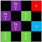
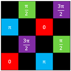
Our proposed signal pattern is illustrated in Figure 2a. The concept of our method is based on the suppression of the fluctuation of signal intensity resulting from constructive or destructive interference with noise-diffracted light waves. The following two points play a key role in our method. One is the employment of a checkerboard pattern. The arrangement of the signal data is limited to every other pixel, whereas the remaining pixels are always OFF, resembling a checkerboard pattern. Since the noise usually comes from adjacent ON pixels, half of the noise diffraction can be cut using a checkerboard pattern. The other is the designed phase mask. In this phase mask, all the adjacent ON pixels in diagonal positions have a phase difference of π/2. Therefore, the noise produced from those pixels will change the phase of signal waves, not their intensity, resulting in the observed total optical-field vector having minimal amplitude modulation and maintaining nearly the same optical intensity as the original signal wave, as shown in Figure 2b.

2.3. Signal Image to Be Input

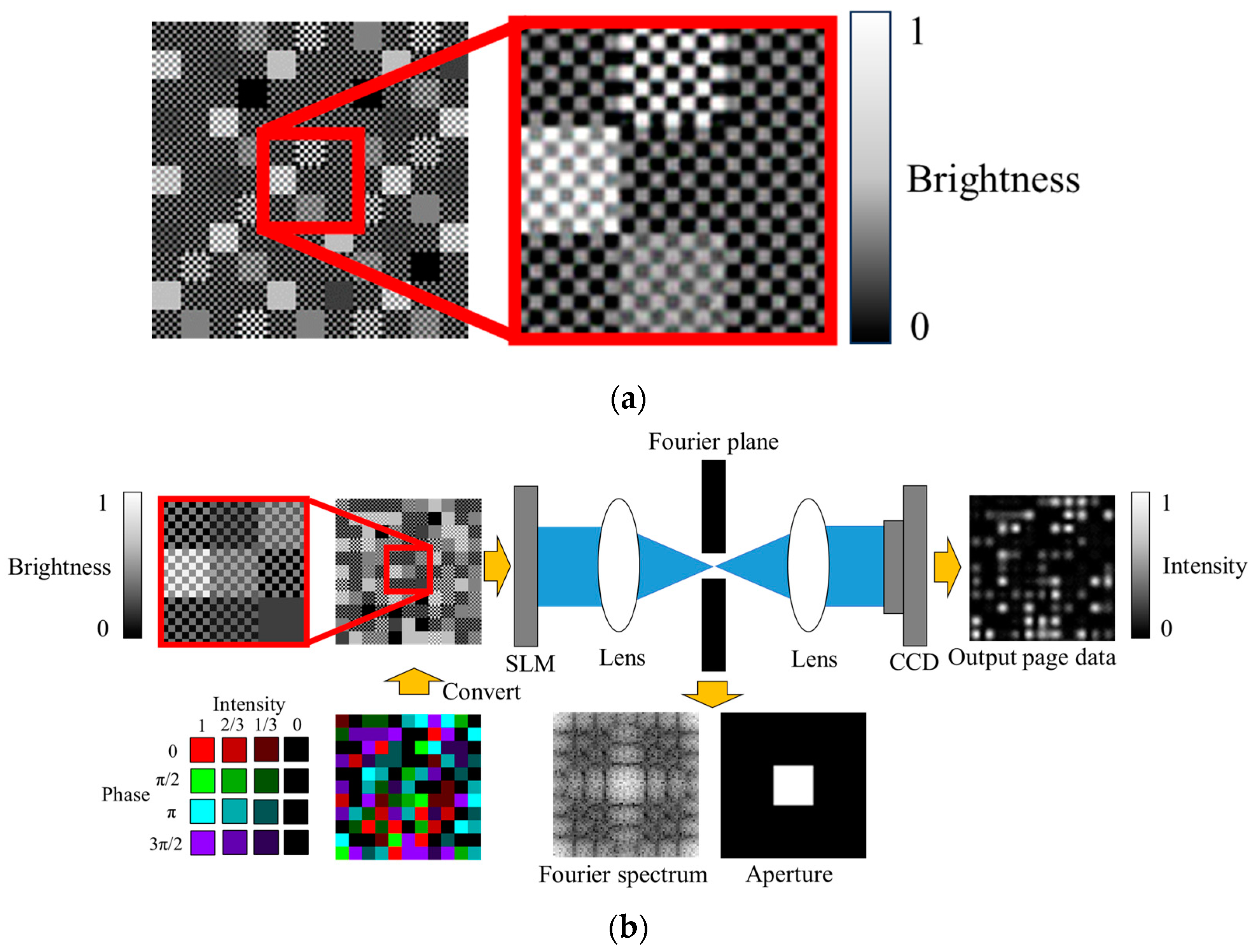
Our method requires imposing both intensity and phase modulation on the signal wave, but using two spatial light modulators (SLMs) complicates the optical system and demands pixel matching. Therefore, we adopted the method of Göröcs et al. [25] to apply intensity and phase modulation with a single SLM. In this method, each data pixel is further divided into smaller pixels, and two different phases are added in a checkerboard pattern, as shown in Figure 3a. This fine checkerboard pattern diffracts a portion of the incoming signal light wave. The first-order diffracted light propagates at a larger diffraction angle due to the higher spatial frequency of the checkerboard pattern. Thus, it is blocked by the aperture inserted in the Fourier plane. The first-order diffracted light intensity and the transmitted, or 0-th-order diffracted light intensity are determined by the difference between the two phases added in the fine checkerboard pattern. Furthermore, the phase of transmitted light wave is equal to the average phase of the two phases. Therefore, by appropriately controlling the two phases added to each data pixel, the intensity and phase modulation can be controlled with a single SLM.
The typical input image used for our simulation and experiments is shown in Figure 3a. It is a gray-scale image that is input to the phase-modulated SLM. In our case, one data pixel was divided into 7 × 7 pixels. That was adopted because 3 × 3 pixels and 5 × 5 have larger errors due to the effect of boundary areas where the checkerboard pattern changes. Even if the signal data size increases, the final recording density is not affected because the hologram size in the Fourier plane is smaller. However, since the number of pixels in the image sensor and SLM is finite, the transfer rate of information that can be transmitted in one page is reduced.

3. Simulation

3.1. Simulation Method

The effectiveness of the proposed method was first verified by numerical simulation. Figure 3b shows the optical system of the signal path assumed in the simulation. For simplicity, we have directly detected the intensity pattern passing through the aperture, disregarding the involvement of holographic recording material. This assumption is reasonable given that the aperture size determines the in-plane hologram size. Although holographic reconstruction may modify the spatial frequency components of the signal image due to off-Bragg diffraction, its impact is identical to that produced by the aperture. The direct light propagation from the SLM to the charge-coupled device (CCD) camera was calculated. The input signal image consists of 1001 × 1001 data pixels. In our method, because half of the pixels are set to OFF pixels, only the other half are the data pixels that carry intensity information. Each data pixel was further divided into 7 × 7 pixels to display a checkerboard pattern for Göröcs’s method. Therefore, the total image size is 7007 × 7007. The designed input-signal wave was first Fourier-transformed by a Fast Fourier transform (FFT) algorithm. The resulting Fourier image was spatially filtered with a square aperture, and finally, the inverse Fourier transform was performed to obtain the light intensity distribution that the imager acquires. Since the amount of crosstalk depends on the aperture size, calculations were performed for various aperture sizes. Here, we introduce a Nyquist ratio (RNyq) as a parameter of the aperture size, defined as the aperture size normalized by the Nyquist size [27,28]. After calculating the light intensity distribution, the average light intensity for each signal intensity level (symbol) was calculated from the light intensity received at each data pixel. The average value of each symbol is employed to determine the decision region of each symbol. In this study, the threshold value was set as the mean value of the two symbol averages. If the retrieved symbol was recognized as a different symbol from the original one, then the corresponding pixel was recorded as an error pixel. These analyses were performed on all data pixels within the output signal image, and the pixel error rate (PxER) was calculated as the ratio of the number of incorrectly detected signal data pixels to the total number of signal data pixels. The detailed conditions of the simulation are summarized in Table 1.
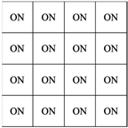
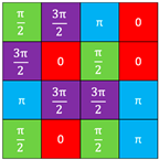
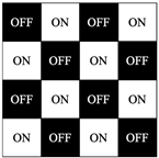
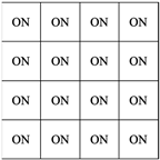
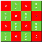
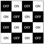
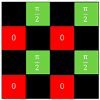
Several other signal patterns were also calculated to verify the effectiveness of our proposed signal arrangement. A list of the tested patterns is shown in Table 2. An ON/OFF amplitude pattern indicates the presence of an intensity signal. When ON, it means that the pixel is a signal pixel with information, and the intensity will be 0, 1/3, 2/3, or 1. If OFF, it means that the pixel is not a signal pixel and the intensity will always be 0. The phase pattern is a fixed mask and does not hold any signal information; it is added to prevent modulation of the signal intensity. The random pattern in Table 2(a) is a typical signal arrangement used in conventional holographic data storage systems, where all pixels are used as information data pixels, and a random phase mask is added to avoid the sharp intensity peak in the Fourier plane. The checkerboard pattern in Table 2(b) was introduced to verify the effect of the checkerboard signal arrangement. The phase in this pattern is also a random phase arrangement. The design two-value pattern in Table 2(c) was used to examine the effect of the phase mask having the phase difference of π/2 between the nearest neighbor pixels. Although all pixels are information data pixels, the phase difference between the top, bottom, left, and right adjacent pixels is always π/2. Table 2(d) was introduced to verify the effect of the checkerboard signal arrangement and the effect of the phase mask having the phase difference of π/2 between the nearest-neighbor pixels. The last pattern (e) is our proposed pattern. Typical signal images of these calculated patterns are shown in Figure 4.

3.2. Simulation Results and Discussion

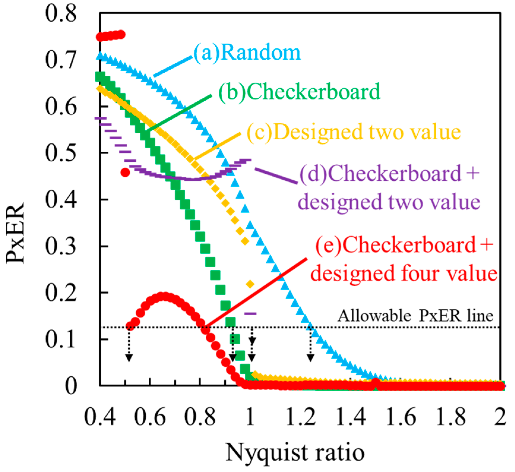
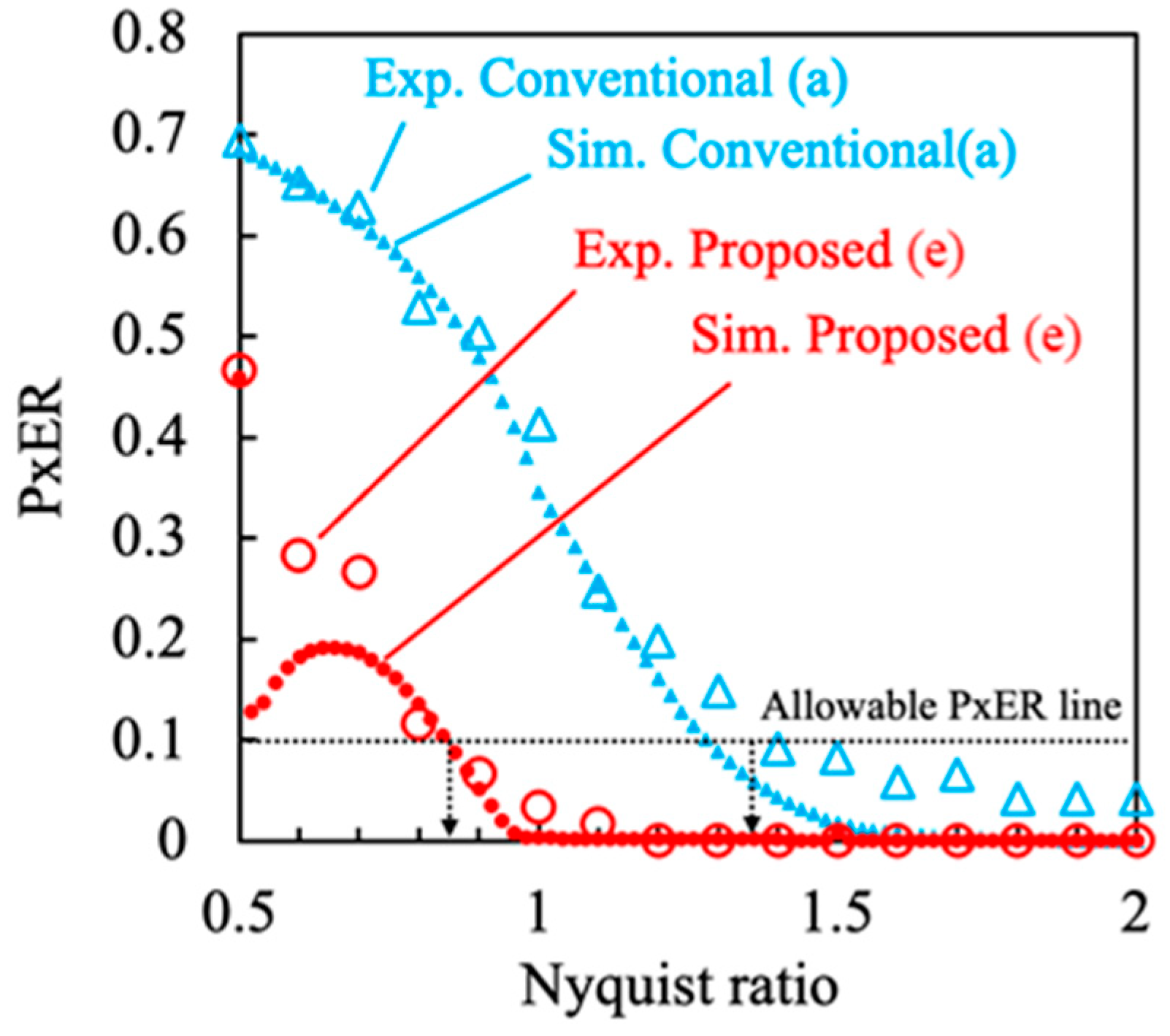
The calculated PxERs are plotted as a function of the Nyquist ratio in Figure 5. The proposed method has a smaller PxER than any other method for most Nyquist ratios, which indicates that the quality of the output signal in our method is better than that in other signal images. Note that the Nyquist sizes for (b), (d) and (e) are not the same as those for (a) and (c) because of the different interpixel lengths. However, in our simulation, the Nyquist ratio, which determines the hologram exposure area Sholo, was calculated using the same Nyquist size. This allowed us to compare recording densities across the patterns.
In general, detection errors must be completely corrected by the error correction code employed by the system. Thus, the error rate must be kept below the specific value the system allows. Conversely, suppose we obtained an error rate smaller than the allowable error rate. In that case, the excess error rate can be used to reduce the hologram exposure area Sholo to increase the recording density. Thus, a decrease in PxER directly leads to an increase in recording density. In the present case, however, it is necessary to consider the single-page capacity C1page. This is because the number of signal data pixels per page in (b), (d) and (e) is half that of (a) and (c), owing to the checkerboard data arrangement. In order to take these considerations into account, we introduce the following recording density factor ξ as a figure of merit of the recording density.
ξ = C R N y q 2  
where C is the code rate representing the average number of data bits expressed by one data pixel. In the present case, the C is equal to 2.0 for (a) and (c) and 1.0 for (b), (d) and (e). Note that the Nyquist ratio, a parameter related to the length of the aperture sides, should be squared, since the recording density is inversely proportional to the exposure area. If we assume that the maximum error rate allowed by the system is 12% [29], then the minimum Nyquist ratios for the methods of (a), (b), (c), (d), and (e) are 1.24, 0.92, 1.01, 1.01, and 0.52, respectively, as is indicated in Figure 5. In this case, the recording density factors for these methods are estimated to be 1.30, 1.17, 1.96, 0.98, and 3.69, respectively. Therefore, the proposed method (e) can theoretically improve the recording density by a factor of 2.8 compared to the conventional method (a).
Such a significant improvement in recording density is responsible for the steep valley of PxER around the Nyquist ratio of 0.5. That valley in PxER is a characteristic feature in our method because other signal patterns exhibit a monotonical increase in PxER with a decreasing Nyquist ratio. There are mainly two reasons for this valley in PxER in (e). One is due to the fact that specific Fourier peaks pass through the aperture at the Nyquist ratio of more than 0.5. The signal image in (e) has a regularly arranged phase pattern, as shown in Table 2. As a result, a sharp intensity peak appears at a specific position in the Fourier image. The passage of these Fourier peaks through the aperture improves the sharpness of the output image and significantly reduces the PxER.
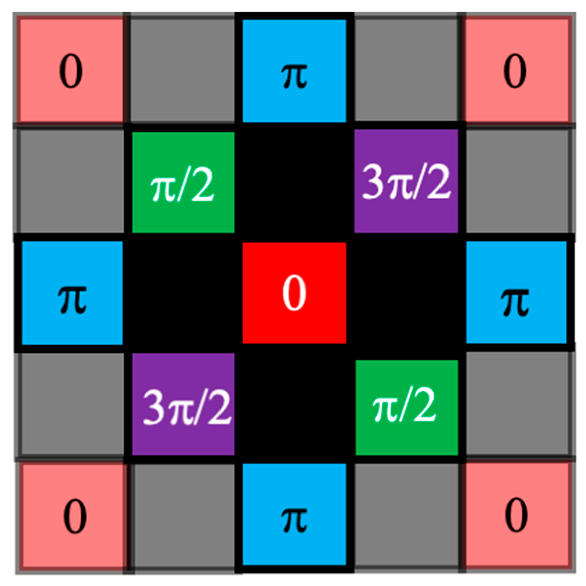
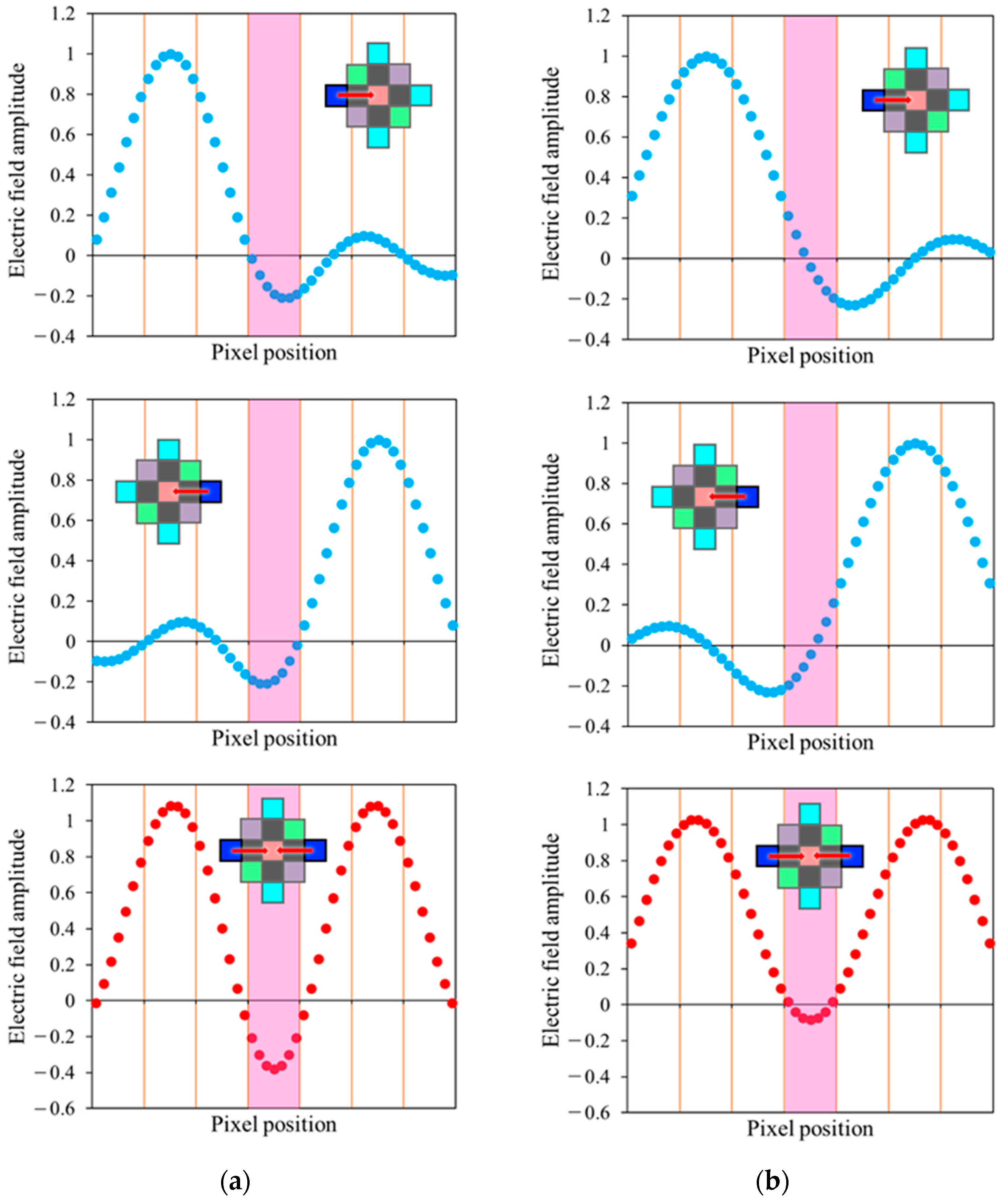
The other is due to the effect of signal data located two pixels apart. The typical phase pattern in our method is shown in Figure 6. As can be seen from the figure, the signal data located two pixels apart from the central data pixel has a phase difference π from the central one. Therefore, light waves leaked from these pixels will largely modulate the central signal light intensity owing to their constructive or destructive interference with the central signal wave. Especially when the Nyquist ratio becomes small, the amount of leakage becomes large, and these interferences significantly impact the accuracy of signal detection. However, at a certain Nyquist ratio, such influence becomes small because that leaked light wave destructively interferes with the light wave leaked from the pixel at the opposite symmetrical position. This situation is illustrated in Figure 7. These figures show the electric field distribution of the leaked light wave from pixels two pixels apart at the Nyquist ratios of (a) 0.66 and (b) 0.52. The leaked electric field distribution for the Nyquist ratio of 0.52 is extended farther than that for the Nyquist ratio of 0.66. However, the sign of the electric field for the Nyquist ratio of 0.52 is switched at the central pixel position. When the intensities of pixels two pixels apart are the same, the total electric field of the central pixel becomes small, owing to destructive interference with the electric field leaked from the opposite side pixel, as shown in the lower part of Figure 7b. Even if the intensities of two pixels are different, the constructive interference never occurs at the central pixel position.
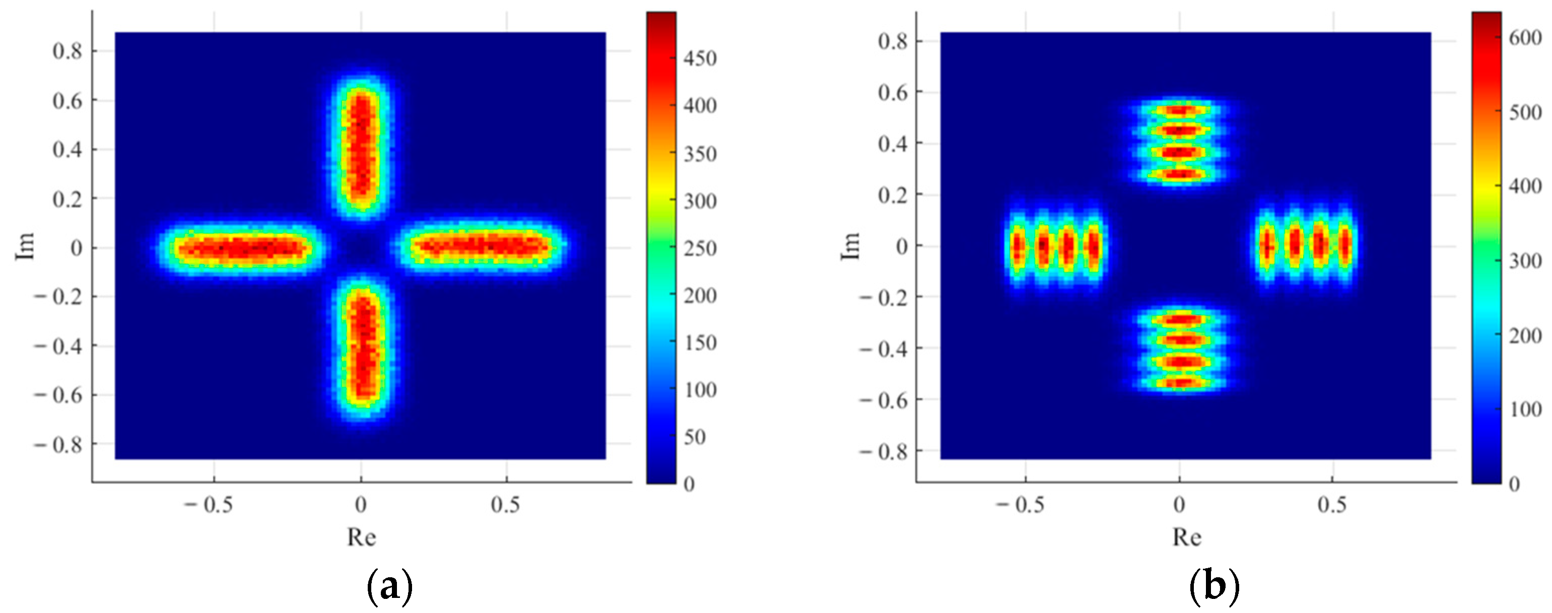
The influence of the π/2 phase difference of the nearest diagonal pixel can be clearly observed at the Nyquist ratio of 0.52, where the effect of the leaked light wave from the two pixels apart is weak. Figure 8 shows two-dimensional histograms in the complex plane at Nyquist ratios of 0.66 and 0.52. In these histograms, the distance from the origin and the azimuth angle represents the light intensity and phase of the detected signal light wave, respectively, and the color represents its frequency of occurrence. At the Nyquist aperture ratio of 0.66, the four intensity signals do not show clear peaks and cannot be distinguished, as shown in Figure 8a. It is because the noise largely spreads in the radial direction due to the effect of light waves leaked from pixels two-pixels apart. In contrast, at the Nyquist aperture ratio of 0.52, where the influence from the pixel two-pixels apart is small, the distribution is spread only in the azimuth direction due to the effect of the nearest diagonal pixels with a phase difference of π/2. Thus, four intensity signal peaks can be observed clearly. Therefore, our proposed signal pattern has the ability to squeeze noise in the radial direction, which can significantly reduce the PxER of the intensity-modulated signals.

4. Experiments

4.1. Experimental Method

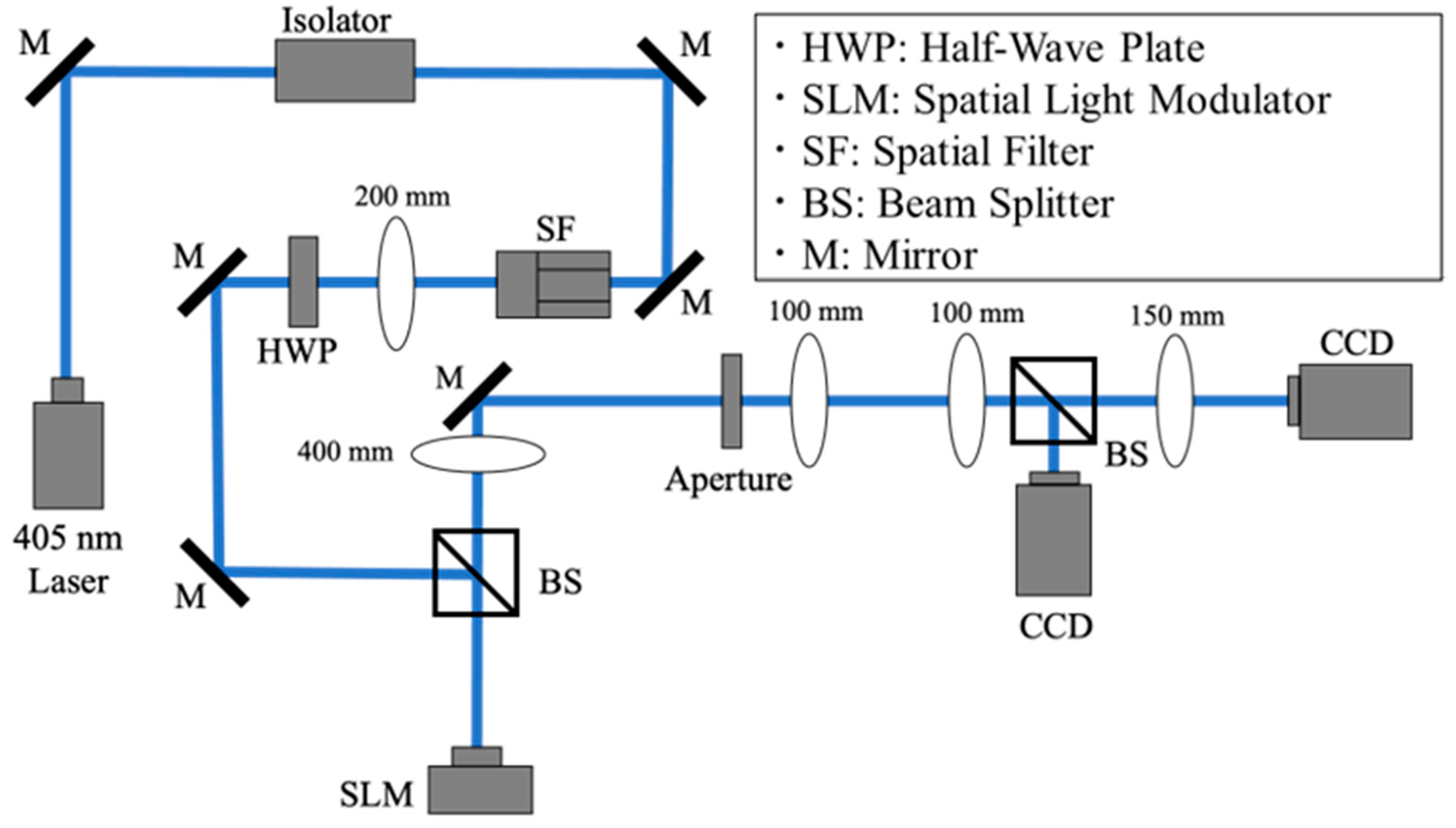
To verify the validity of our method, optical experiments were conducted. Figure 9 shows the optical system used in the experiment. A single-mode semiconductor laser operating at a wavelength λ of 405 nm (LM405-PLR40, ONDAX, Inc., Monrovia, CA, USA) was used as the light source. First, the laser beam was passed through a spatial filter to form a clean spherical wave. Next, the laser light was modulated with an SLM (X10468-05, Hamamatsu Photonics K. K., Shizuoka, Japan) to give the desired signal phase pattern. The phase-modulated signal wave was focused by a lens with a focal length f of 400 mm and low-pass filtered by a variable square aperture (SLX-1, Sigma Koki Co., Ltd., Tokyo, Japan) inserted in the Fourier plane. As in the simulations, output images were acquired at various Nyquist ratios. A variable aperture, manually adjustable in 10 µm increments, was used to change the aperture size. Finally, a CCD camera (PL-B953U, Pixellink, Ottawa, ON, Canada), which detects the intensity distribution with 8-bit resolution, was placed on the Fourier and the image planes, respectively. Note that the CCD camera on the Fourier plane was used to adjust the aperture position. The pixel pitch was 20 µm for the SLM and 4.65 µm for the CCD. All the signal data consisted of 28 × 28 SLM pixels. Thus, the pixel pitch a of the data pixels was 560 µm. The corresponding Nyquist size w was 289 µm, calculated by the relationship w = /a. The Nyquist ratio was calculated as an aperture size divided by the Nyquist size, as in the simulation.
One data pixel of the output image was oversampled by 44 × 44 pixels in a CCD camera. Thus, the light intensities of the 44 × 44 pixels within the data pixel were averaged to obtain the signal intensity level of that data pixel. A single data page consisted of 13 × 13 pixels, and the 11 × 11 pixels in the center, excluding the outermost pixels, were used for evaluation. Since half of these pixels are OFF pixels due to the checkerboard pattern, the number of signal data pixels is 60. Using these signal data pixels, the PxER for each method was calculated. The parameters used in the experiments are summarized in Table 3.
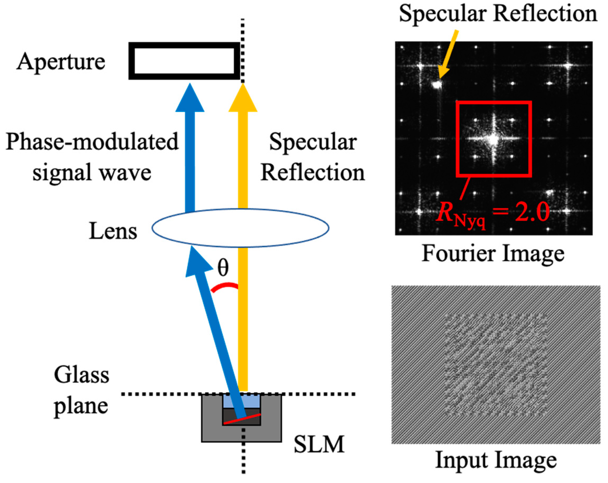
In our experiment, the linear phase encoding method [13] was applied to avoid the influence of the specular reflection at an SLM glass surface. In this method, a uniform phase gradient is added to the input signal pattern to spatially separate the desired light wave modulated by the SLM from the unwanted specular reflection from the protective glass surface of the SLM. Then, this specular reflection can be blocked by the aperture inserted in the Fourier plane so that it does not affect the output image. A typical example of the input image with the linear phase encoding is shown in Figure 10. In our experiment, a linear phase was added in the diagonal direction so that specularly reflected light cannot pass through the aperture at a Nyquist ratio of less than 3.0, as shown in Figure 11. In this case, θ is 0.109°.

4.2. Experimental Results and Discussion

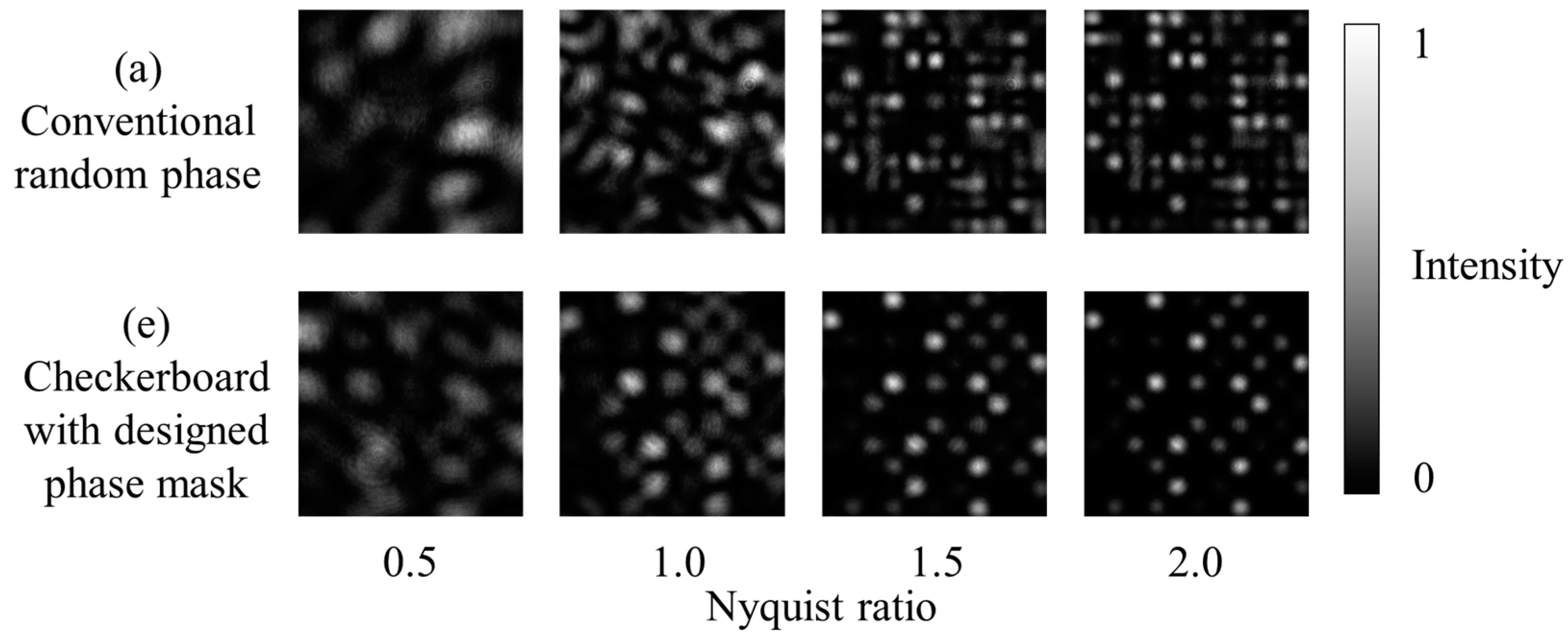
Figure 12 shows acquired images for the conventional random phase pattern of (a) and the proposed checkerboard pattern with the designed phase mask of (e). It can be clearly seen that as the Nyquist ratio decreases, the crosstalk between pixels increases, and the pixel boundaries become blurred. It can also be seen that in the case of the proposed method of (e), the pixel boundaries are clearer than in the conventional method. From this acquired image, PxER was calculated similarly to the simulation. The results were plotted in Figure 13. For comparison, the simulation results of Section 3.2 were also plotted. Although the PxERs at Nyquist ratios of 0.6 and 0.7 in the experiment were slightly higher than those in the simulation, the experimental results were in excellent agreement with the simulated results. Thus, we can conclude that the validity of our simulation results was well confirmed.
In terms of the recording density, if we assume that the allowable PxER is 10%, the same level as the simulation, the recording density factor is calculated to be 1.45 and 1.05 for the proposed and conventional methods, respectively. Therefore, it is experimentally demonstrated that the recording density can be improved by a factor of 1.4 compared to the conventional method. The improvement factor of the recording density is lower than that of the simulation. This is because the PxER at the Nyquist ratio of 0.6 was slightly higher than that of the simulation and probably because the Nyquist ratio cannot be adjusted with a resolution of less than 0.1 in our experimental condition. If an allowable PxER is large, that is 30%, which is comparable with the PxER at the Nyquist ratio of 0.6 in our proposed method, the recording density factors are 2.78 and 1.71 for the proposed and conventional methods, respectively. In this case, the recording density can be improved by a factor of 1.6.

5. Conclusions

We have proposed a new two-dimensional signal pattern for intensity-modulated multilevel signals and verified its effectiveness through simulations and experiments. In order to reduce the influence of the crosstalk noise, the proposed method uses a checkerboard pattern and the designed phase mask where all the adjacent ON pixels in diagonal position have a phase difference of π/2. The proposed method showed lower PxER than the conventional signal pattern. The data capacity of our proposed signal pattern is half of that of the conventional one because the proposed method forces half of the pixel data to be turned off, according to the checkerboard pattern. However, by selecting an appropriate aperture size, the reduction of the single-page data capacity is compensated, and the overall recording density can be improved.
This study evaluated only a single-page recording, but a further improvement in recording density can be expected using this method for angle and shift multiplexing. The proposed method may play an important role in the HDS system where high recording density is required.
Recently, a published pixelated single-layer LC (liquid crystal) device showed versatile and tunable vectorial holography [30]. Such LC devices, which can modulate intensity and phase on a pixel-by-pixel basis, increase the rate of signals transmitted on a single page. Our signal this time is divided into 7 × 7 inside the information pixel for simultaneous intensity and phase modulation, but such a division is no longer necessary in those LC devices.

Author Contributions

Conceptualization, T.S. and R.F.; methodology, T.N. and R.F.; software, T.N.; validation, T.N. and R.F.; formal analysis, T.N., S.H., T.S. and R.F.; investigation, T.N., S.H., T.S. and R.F.; writing—original draft preparation, T.N. and R.F.; writing—review and editing, S.H., T.S. and R.F.; visualization, T.N. and R.F.; supervision, R.F.; project administration, R.F.; funding acquisition, R.F. All authors have read and agreed to the published version of the manuscript.

Funding

This research was partially funded by JSPS KAKENHI, grant number 21K04917.

Institutional Review Board Statement

Not applicable.

Informed Consent Statement

Not applicable.

Data Availability Statement

The data presented in this study are available on request from the corresponding author.

Conflicts of Interest

The authors declare no conflict of interest.

References

  1. Coufal, H.J.; Psaltis, D.; Sincerbox, G.T. Holographic Data Storage; Springer: Berlin, Germany, 2000. [Google Scholar]
  2. Curtis, K.; Dhar, L.; Hill, A.; Wilson, W.; Ayres, M. Holographic Data Storage: From Theory to Practical Systems; Wiley: New York, NY, USA, 2010. [Google Scholar]
  3. Anderson, K.; Curtis, K. Polytopic Multiplexing. Opt. Lett. 2004, 29, 1402–1404. [Google Scholar] [CrossRef] [PubMed]
  4. Mok, F.H. Angle-Multiplexed Storage of 5000 Holograms in Lithium Niobate. Opt. Lett. 1993, 18, 915–917. [Google Scholar] [CrossRef]
  5. Shimura, T.; Ichimura, S.; Fujimura, R.; Kuroda, K.; Xiaodi, T.; Horimai, H. Analysis of a Collinear Holographic Storage System: Introduction of Pixel Spread Function. Opt. Lett. 2006, 31, 1208–1210. [Google Scholar] [CrossRef] [PubMed]
  6. Sato, M.; Ogasawara, M.; Ito, Y.; Tanaka, S.; Iida, T. New Coaxial Interference Method for Consumer Holographic Memory. Jpn. J. Appl. Phys. 2007, 46, 3850–3854. [Google Scholar] [CrossRef]
  7. Tanaka, K.; Hara, M.; Tokuyama, K.; Hirooka, K.; Ishioka, K.; Fukumoto, A.; Watanabe, K. Improved Performance in Coaxial Holographic Data Recording. Opt. Express 2007, 15, 16196–16209. [Google Scholar] [CrossRef]
  8. Burr, G.W.; Barking, G.; Coufal, H.; Hoffnagle, J.A.; Jefferson, C.M.; Neifeld, M.A. Gray-Scale Data Pages for Digital Holographic Data Storage. Opt. Lett. 1998, 23, 1218–1220. [Google Scholar] [CrossRef]
  9. Okamoto, A.; Kunori, K.; Takabayashi, M.; Tomita, A.; Sato, K. Holographic Diversity Interferometry for Optical Storage. Opt. Express 2011, 19, 13436. [Google Scholar] [CrossRef]
  10. Nobukawa, T.; Nomura, T. Multilevel Recording of Complex Amplitude Data Pages in a Holographic Data Storage System Using Digital Holography. Opt. Express 2016, 24, 21001. [Google Scholar] [CrossRef]
  11. John, R.; Joseph, J.; Singh, K. Holographic Digital Data Storage Using Phase-Modulated Pixels. Opt. Lasers Eng. 2005, 43, 183–194. [Google Scholar] [CrossRef]
  12. Bunsen, M.; Umetsu, S.; Takabayashi, M.; Okamoto, A. Method of Phase and Amplitude Modulation/Demodulation Using Datapages with Embedded Phase-Shift for Holographic Data Storage. Jpn. J. Appl. Phys. 2013, 52, 09LD04. [Google Scholar] [CrossRef]
  13. Nobukawa, T.; Nomura, T. Linear Phase Encoding for Holographic Data Storage with a Single Phase-Only Spatial Light Modulator. Appl. Opt. 2016, 55, 2565–2573. [Google Scholar] [CrossRef] [PubMed]
  14. Nobukawa, T.; Nomura, T. Digital Super-Resolution Holographic Data Storage Based on Hermitian Symmetry for Achieving High Areal Density. Opt. Express 2017, 25, 1326–1338. [Google Scholar] [CrossRef] [PubMed]
  15. Muroi, T.; Katano, Y.; Kinoshita, N.; Ishii, N. Dual-Page Reproduction to Increase the Data Transfer Rate in Holographic Memory. Opt. Lett. 2017, 42, 2287–2290. [Google Scholar] [CrossRef] [PubMed]
  16. Kim, K.-T.; Cho, B.-C.; Kim, E.-S.; Gil, S.-K. Performance Analysis of Phase-Code Multiplexed Holographic Memory. Appl. Opt. 2000, 39, 4160–4167. [Google Scholar] [CrossRef] [PubMed]
  17. Takabayashi, M.; Okamoto, A.; Tomita, A.; Bunsen, M. Symbol Error Characteristics of Hybrid-Modulated Holographic Data Storage by Intensity and Multi Phase Modulation. Jpn. J. Appl. Phys. 2011, 50, 09ME05. [Google Scholar] [CrossRef]
  18. Schwider, J.; Burow, R.; Elssner, K.-E.; Grzanna, J.; Spolaczyk, R.; Merkel, K. Digital Wave-Front Measuring Interferometry: Some Systematic Error Sources. Appl. Opt. 1983, 22, 3421–3432. [Google Scholar] [CrossRef] [PubMed]
  19. Fujimura, R. Investigation of Noise Characteristics of Multivalued Signals and Estimation of Single-Page Storage Density in Holographic Data Storage. ITE Trans. Media Technol. Appl. 2021, 9, 144–152. [Google Scholar] [CrossRef]
  20. Ishii, T.; Fujimura, R. Interpixel Crosstalk Cancellation on Holographic Memory. Jpn. J. Appl. Phys. 2017, 56, 09NA10. [Google Scholar] [CrossRef]
  21. Nobukawa, T.; Barada, D.; Nomura, T.; Fukuda, T. Orthogonal Polarization Encoding for Reduction of Interpixel Cross Talk in Holographic Data Storage. Opt. Express 2017, 25, 22425. [Google Scholar] [CrossRef]
  22. Hong, J.; McMichael, I.; Ma, J. Influence of phase masks on cross talk in holographic memory. Opt. Lett. 1996, 21, 1694–1696. [Google Scholar] [CrossRef]
  23. Bernal, M.-P.; Burr, G.W.; Coufal, H.; Grygier, R.K.; Hoffnagle, J.A.; Jefferson, C.M.; Oesterschulze, E.; Shelby, R.M.; Sincerbox, G.T.; Quintanilla, M. Effects of multilevel phase masks on interpixel cross talk in digital holographic storage. Appl. Opt. 1997, 36, 3107–3115. [Google Scholar] [CrossRef] [PubMed]
  24. Saito, M.; Fujimura, R. Noise Suppression in Intensity-Modulated Multivalued Holographic Memory. In Proceedings of the International Workshop on Photonics Polymer for Innovation, Suwa, Nagano, Japan, 16 October 2018. [Google Scholar]
  25. Göröcs, Z.; Erdei, G.; Sarkadi, T.; Ujhelyi, F.; Reményi, J.; Koppa, P.; Lorincz, E. Hybrid Multinary Modulation Using a Phase Modulating Spatial Light Modulator and a Low-Pass Spatial Filter. Opt. Lett. 2007, 32, 2336. [Google Scholar] [CrossRef] [PubMed]
  26. Bernal, M.-P.; Burr, G.W.; Coufal, H.; Quintanilla, M. Balancing Interpixel Cross Talk and Detector Noise to Optimize Areal Density in Holographic Storage Systems. Appl. Opt. 1998, 37, 5377. [Google Scholar] [CrossRef] [PubMed]
  27. Lee, S.-H.; Lim, S.-Y.; Kim, N.; Park, N.-C.; Yang, H.; Park, K.-S.; Park, Y.-P. Increasing the Storage Density of a Page-Based Holographic Data Storage System by Image Upscaling Using the PSF of the Nyquist Aperture. Opt. Express 2011, 19, 12053–12065. [Google Scholar] [CrossRef] [PubMed]
  28. Lin, X.; Hao, J.; Wang, K.; Zhang, Y.; Li, H.; Tan, X. Frequency Expanded Non-Interferometric Phase Retrieval for Holographic Data Storage. Opt. Express 2020, 28, 511–518. [Google Scholar] [CrossRef] [PubMed]
  29. Ishii, N.; Katano, Y.; Muroi, T.; Kinoshita, N. Spatially Coupled Low-Density Parity-Check Error Correction for Holographic Data Storage. Jpn. J. Appl. Phys. 2017, 56, 09NA03. [Google Scholar] [CrossRef]
  30. Wang, Z.Y.; Zhou, Z.; Zhang, H.; Wei, Y.; Yu, H.G.; Hu, W.; Chen, W.; Dai, H.T.; Ma, L.L.; Qiu, C.W.; et al. Vectorial liquid-crystal holography. eLight 2024, 4, 5. [Google Scholar] [CrossRef]
Figure 1. Typical optical setup for the recording process in holographic data storage systems.
Photonics 11 00507 g001
Figure 2. Concept of crosstalk noise suppression. (a) Designed signal pattern. (b) Interference between signal and noise optical fields.
Photonics 11 00507 g002
Figure 3. Signal and system overview. (a) Input image of the proposed pattern used in our simulation and experiment. (b) Schematic of the optical system assumed in the simulation.
Photonics 11 00507 g003
Figure 4. Examples of the simulated signal images.
Photonics 11 00507 g004
Figure 5. Influence of the input signal arrangement on the pixel error rate.
Photonics 11 00507 g005
Figure 6. The phase pattern in our proposed signal pattern.
Photonics 11 00507 g006
Figure 7. Influence of the electric field leaked from the pixel two-pixels apart on the central pixel at (a) Nyquist ratio of 0.66 and (b) Nyquist ratio of 0.52.
Photonics 11 00507 g007
Figure 8. Two-dimensional histograms of the detected signal in the complex plane at a Nyquist ratio of (a) 0.66 and (b) 0.52.
Photonics 11 00507 g008
Figure 9. Schematic diagram of the experimental optical setup.
Photonics 11 00507 g009
Figure 10. A typical example of the SLM input image with the linear phase-encoding.
Photonics 11 00507 g010
Figure 11. Spatial separation of the desired light wave modulated by the SLM and the unwanted specular reflection from the protective glass surface of the SLM.
Photonics 11 00507 g011
Figure 12. Examples of acquired images at various Nyquist ratios.
Photonics 11 00507 g012
Figure 13. Comparison of the Nyqusit ratio dependence of PxER in the simulation and experiment.
Photonics 11 00507 g013
Table 1. Simulation condition.
Number of data pixels1001 × 1001 data pixels
Number of pixels within one data pixel7 × 7 pixels
Nyquist size1001 ×1001 pixels
Nyquist ratio0.5–2.0
Table 2. Simulated signal patterns.
Pattern NameAmplitude PatternPhase Pattern
(a) Random(A) All pixels Photonics 11 00507 i001(I) Random
Photonics 11 00507 i002
(b) Checkerboard(B) Checkerboard
Photonics 11 00507 i003
(II) Random
Photonics 11 00507 i004
(c) Designed two value(A) All pixels
Photonics 11 00507 i005
(III) Regular (0, π/2)
Photonics 11 00507 i006
(d) Checkerboard
+
Designed two value
(B) Checkerboard
Photonics 11 00507 i007
(IV) Regular (0, π/2)
Photonics 11 00507 i008
(e) Checkerboard
+
Designed four value
(B) Checkerboard
Photonics 11 00507 i009
(V) Regular (0, π/2, π, 3π/2)
Photonics 11 00507 i010
Table 3. Experimental condition.
Size of the data pixel560 μm
Nyquist size289 μm
Number of signal data pixels within a page60 data pixels
Number of detector pixels within one data pixel44 × 44 detector pixels
Nyquist ratio0.5–2.0
Disclaimer/Publisher’s Note: The statements, opinions and data contained in all publications are solely those of the individual author(s) and contributor(s) and not of MDPI and/or the editor(s). MDPI and/or the editor(s) disclaim responsibility for any injury to people or property resulting from any ideas, methods, instructions or products referred to in the content.