Article

Rare-Earth-Ion (RE3+)-Doped Aluminum and Lanthanum Borates for Mobile-Phone-Interrogated Luminescent Markers

1
Department of Chemical Technology, Faculty of Chemistry, Plovdiv University “Paisii Hilendarski” 24 Tsar Asen Str., 4000 Plovdiv, Bulgaria
2
Photonics Research Center, Université du Québec en Outaouais, rue 101 St-Jean Bosco, Gatineau, QC J8X 3G5, Canada
3
Central Laboratory of Applied Physics, Bulgarian Academy of Sciences, 61 Sanct Peterburg Blvd., 4000 Plovdiv, Bulgaria
*
Author to whom correspondence should be addressed.
Photonics 2024, 11(5), 434; https://doi.org/10.3390/photonics11050434
Submission received: 23 March 2024 / Revised: 21 April 2024 / Accepted: 29 April 2024 / Published: 6 May 2024

Abstract

:
In this paper, we present the synthesis and luminescent spectra of rare-earth (RE)-doped aluminum and lanthanum borates intended to serve as narrow excitation–emission band fluorescent markers. We perform a detailed 3D excitation–emission matrix (EEM) analysis of their spectra, compare the measurements from both standard and mobile phone spectrometers, and outline the basic differences and advantages of each method. While smartphones have a different and non-uniform spectral response compared to standard spectrometers, it is shown that they offer a number of advantages such as contactless interrogation, efficient suppression of the UV excitation light, and simultaneous spectral analysis of spatially arranged arrays of fluorescent markers. The basic emission peaks have been observed and their corresponding electronic transitions identified. The obtained results show that the rare-earth-doped La and Al borates feature excitation–emission bandwidths as low 15 nm/12 nm, which makes them particularly appropriate for use as luminescent markers with UV LED excitation and smartphone interrogation.

1. Introduction

In recent years, inorganic borate materials synthesized by the solid-state method have attracted considerable attention due to their promising chemical and physical properties and applications such as flat panel displays, white-light-emitting diodes (WLEDs), solar cells, thermoluminescent dosimeters, plasma displays, etc. [1]. In these applications, rare earth (RE) compounds are highly valued due to their unique electron configurations. Key RE3+ elements such as La, Ce, Sm, Eu, Gd, Tb, and Dy primarily exist in the +3 valence state, characterized by up to 14 electrons in the 4f shell. These ions can also occur in +4 and +2 valence states when their f shells are partially filled. In these materials, luminescence occurs through processes including absorption, excitation, energy transfer, and emission, triggered by electron transitions between energy orbitals. In these systems, the host material plays an important role. It acts as a passive matrix defining the spatial positions of dopant ions, termed activators, and as an active participant that influences the spectroscopic properties of these activators [2]. For instance, terbium (Tb3+) and cerium (Ce3+) ions, with their 4f-5d excited states, demonstrate efficient luminescence when incorporated into lanthanum and aluminum compounds [3].
Borate compounds can feature a three- or four-fold coordination of borate atoms, which perform as excellent hosts for luminescent materials due to their structural diversity [4]. Rare earth elements like Sm, Tb, Eu, Ce, Gd, and Dy, when doped into lanthanum and aluminum borates, can enhance luminescence properties. For example, Eu3+ shows strong red/orange luminescence, while Tb3+ emits in the green spectrum [5]. Various synthesis methods such as the high-temperature solid-state reaction, sol–gel, hydrothermal synthesis, and solution combustion are employed, with the solid-state reaction noted for its simplicity, high yield, and environmentally friendly profile. The applications of Eu-doped La and Al borates are diverse due to their unique excitation–emission spectra [6,7]. These include uses in anti-counterfeiting [8,9] and potential applications in plasma displays [10]. In all of the above and in other applications, it is of crucial importance to be able to detect, identify, and track such luminescent markers remotely using worldwide available smartphones [11,12,13,14,15,16], which are more affordable than professional spectrometers and are compatible with Internet of Things technology, thus allowing intelligent sensing networks to be developed.
In the present work, we synthesized a series of luminescent lanthanum and aluminum borate samples doped with various rare earth elements and their combinations in order to obtain a unique coding for various applications. We measured the 3D excitation–emission spectra of the samples with a standard optical fiber spectrophotometer and with a smartphone in combination with a transmission diffraction grating, referred to hereafter as a smartphone or mobile phone spectrometer.

2. Synthesis of the Eu3+-Doped Borates

2.1. Materials

The following reagents of analytical grade purity were used for the synthesis of luminescent materials: La2O3 (lanthanum (III) oxide, 99.9%) and Al2O3 (aluminum oxide for chromatographic purposes 99%), purchased from Alfa Aesar, H3BO3 (boric acid, 99%, index # 005-007022-2), Eu2O3 (europium (III) oxide, 99.99% (trace metal basis), Acros, CAS: 1308-96-9), Sm2O3, Dy2O3, Gd2O3, Ce(SO4)2 × 4 H2O, and TbF3.

2.2. Synthesis of LaBO3: RE and AlBO3: RE Phosphors

In our experiments, LaBO3: RE and AlBO3: RE (Re—Eu2O3, Sm2O3, Dy2O3, Gd2O3, Ce(SO4)2 × 4 H2O, and TbF3) phosphors were synthesized by the solid-state method. The solid-state synthesis was carried out in a muffle furnace LM 312.07 with a G400 controller and a temperature range of 0–1200 °C. The raw materials La2O3, Al2O3, and an excess of H3BO3 −45% were used according to the stoichiometric formulas shown in Equations (1) and (2):
La2O3 + 2 H3BO3 →  2 LaBO3 + 3 H2O
Al2O3 + 2 H3BO3 →   2 AlBO3 + 3 H2O
All of these samples were doped with a mol % varying from 1 to 3 mol % of each rare earth compound and a combination of them as shown in Table 1. For the synthesis, reagents were weighed, mixed, and well-homogenized. The prepared mixtures were placed in porcelain crucibles. In the muffle furnace, the samples were heated in a controlled manner, where slow heating at a rate of ∼15 °C/min was applied to set the temperature to 1050 °C for samples A3–A11, maintained for 6 h, and 1000 °C for samples B1–B12, A1, and A2, again for 6 h, and after that they were left in the furnace and cooled slowly for 16 h. After cooling, the samples of LaBO3: RE were a fine white powder and the AlBO3: RE samples were in a crystalline-like form. Furthermore, they could be crushed into a fine powder. In order to compare the host-to-activator efficiency in LaBO3/AlBO3, we synthesized LaBO3/AlBO3 doped with different lanthanide ions and combinations of them (Eu3+, Sm3+, Dy3+, Gd3+, Ce4+, Eu3+/Tb3+, Eu3+/Ce4+, Eu3+/Gd3+, and Eu3+/Gd3+/Tb3+). The combination of rare earth (RE) ions in LaBO3 and AlBO3 matrices improves their optical properties, making them suitable for various applications and easy to check using smartphone equipment. Cerium ions were employed as a co-doping agent because they are capable of transferring energy to other RE ions such as europium (Eu3+), which significantly enhances their luminescent properties. In samples A8 and B8, for example, the emission of Eu3+ ions was greatly enhanced by the energy transfer from cerium to europium ions. When combined with Eu3+, gadolinium performs as a sensitizing agent, improving the luminescence efficiency of europium ions. This is due to the half-filled orbital of gadolinium ions. Therefore, the combination of gadolinium and europium ions can largely enhance the luminescent properties of borate materials.

3. Fluorescence Spectra

3.1. Experimental Setup

The experimental setup used for the measurement of the fluorescence spectra with both a standard spectrometer and mobile phone spectrometer is shown in Figure 1a,b. A laser-driven light source (Energetiq, Wilmington, MA, USA) generates white light in the 190–2500 nm range, which is coupled to an Ocean Optics, Orlando, FL, USA (QE 65000) monochromator via a 1 mm-diameter large core fiber. The optical fiber spectrometer covers a range from 200 to 900 nm. A 1 mm hole is drilled in a plastic platform, in which are installed 600 μm core lead-in and lead-out fibers at 90° with respect to each other. The lead-in fiber excites the sample, and the lead-out fiber couples the fluorescence and scattered light to the standard Ocean Optics (OO) spectrometer as shown in Figure 1a. The fluorescent sample is observed by the smartphone camera from a distance of about 15 cm, at which distance the smartphone can focus on the fluorescent sample. The mobile phone used is a Samsung Galaxy A51 (2400 × 1080 pixels).

3.2. Measurements with a Spectrometer and a Monochromator

3.2.1. Excitation–Emission Spectra

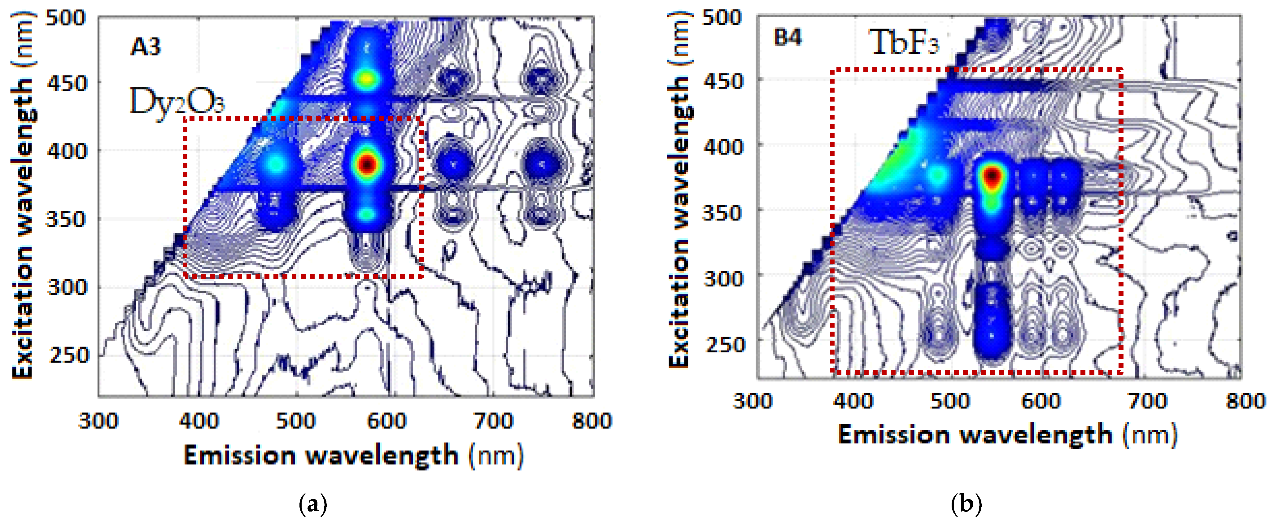
The standard procedure is to scan the excitation wavelength λ’ within a certain range and measure the luminescence spectrum for each excitation wavelength, which allows us plot 3D excitation–emission spectra, the topographic views of which are shown for sample A3 and B4 in Figure 2. It is well known that lanthanide ions have very low absorption coefficients (ε ≤ 1 M−1 cm−1) [15]. To increase light emission, the lanthanide ion can be doped into suitable matrices.
The lowest excited energy level (4F9/2) of the Dy3+ ion (478 nm) (A3) is similar to that (5D4) of the Tb3+ ion (490 nm) (B4), and dysprosium (III) complexes exhibit the characteristic 4F9/26H13/2 and 4F9/26H15/2 transitions leading to blue (around 478 nm) and the most intensive emission, yellow (around 574 nm), respectively, as shown in Figure 2a [16]. The emission spectra in sample B4 are in two luminescence bands—a weak emission at around 481 nm in blue region corresponding to the transitions 5D47F6 obeys the magnetic dipole transition selection rule of ΔJ = ±1 [17,18] and a very strong one centered at 543 nm, relevant to transition 5D47F5, in strong green region, respectively, as shown in Figure 2b.
When a sample is doped with Tb3+ and Eu3+, additional luminescence bands are observed as seen in Figure 2c for A7. The detailed spectroscopic analysis shows that these bands correspond to the 5D07FJ (J = 1 ÷ 4) transitions of Eu3+, specifically 5D07F2 (Eu3+) and 5D47F5 (Tb3+) [19]. Their relative band intensities depend strongly on the concentrations of Tb3+ and Eu3+ in the materials. Figure 2c shows luminescent bands located in the spectral range of 590–620 nm, where both the 5D47F5 transitions of Tb3+ and 5D07FJ (J = 0, 1) of Eu3+ exist, suggesting a Tb3+ → Eu3+ energy transfer process. The reverse process, i.e., Eu3+ → Tb3+, is not observed [20].
The emission of the cerium ion originates from the allowed transition of 4f0 5d1 → 4f1 5d0. It is noted that d ↔ f transitions depend strongly on the ligand field, allowing the emission peak of the cerium ion to range from ultraviolet to visible wavelengths [21].
The excitation spectrum of sample A8 in Figure 2e exhibits a broad band with two intense peaks at around 620 nm when excited by different sources: at 290 nm, corresponding to the 2F5/2 → 5d2 transition, and at 390 nm. In comparison, sample B8 (Figure 2f) shows a band with one intense peak at around 620 nm when excited by a source wavelength of 390 nm.
For a europium-to-cerium ion ratio of 2:1, the emission intensities of Eu3+ are higher compared to those of the cerium ion, which is indicative of efficient energy transfer from the cerium ion to Eu3+. The dominant emission line observed is the 5D0–7F2 transition at around 620 nm, with all other lines being very weak in intensity, suggesting a low probability of the presence of orange and green Eu3+ emission lines [22].
Under the charge transfer excitation wavelength, the cerium ion emission band is observed along with the Eu excitation lines. The cerium emission band extends to cover all the Eu excitation lines, indicating that Ce transfers some of its energy to the Eu ion. Increasing the Eu concentration enhances the intensity of Eu lines while decreasing the intensity of the Ce emission band. Thus, the energy transfer process is incomplete, likely involving both radiative and non-radiative energy transfers in samples A8 and B8, with Ce acting as the sensitizer and the Eu ion as the activator in the host matrix [23].
After direct Eu3+ excitation at 394 nm, the non-radiative relaxation (NR) takes Eu3+ down to the 5D0 luminescence level. The excitation peaks of Gd3+ are found at around 275 nm, corresponding to the energy transfer of 8S7/26I7/2 for samples with aluminum and lanthanum borate, as shown in Figure 3a,b. At this state, a few Gd3+ ions emit photons while most of the Gd3+ transfers energy to the Eu3+ ion. The Eu3+ acceptors then drop their energy to the 5D0 level for luminescence. In the case of charge transfer excitation at 260 nm, Eu3+ receives an electron from O2, converting it to Eu2+ at the ground state with higher vibrational levels, as shown in Figure 2h. Some Eu2+ ions transfer energy to Gd3+, while the remaining Eu2+ thermalizes non-radiative relaxation to the lowest vibrational level of the ground state before transferring energy to Eu3+. Then, the Eu3+ and Gd3+ ions emit photons, and most of the Gd3+ also transfers energy to Eu3+. Since the excitation energy at 260 nm is close to the 6D5/2 level of Gd3+, there exists the probability that light at 260 nm could also excite the Gd3+ ions. From these mechanisms, the Gd3+ → Eu3+ energy transfer is a key process [24]. The most intensive peak is at 613 nm for both of samples (A10 and B10), which is due to an electronic transition of Eu3+ (5D07F2).

3.2.2. Excitation–Emission Bandwidths

The 3D plots allow us to identify the excitation wavelength λ’max of maximum intensity observed at the emission wavelength λmax. In Figure 3, we observe these spectra as narrow excitation–emission maxima.
More details on the excitation spectra, the energy diagrams, and the FTIR spectra of these samples are presented in ref. [25].

4. Measurements with a Smartphone and a Monochromator

To measure the 3D excitation–emission spectra using a smartphone, we make use of the optical scheme in Figure 1b. The scheme allows two options: without a lens and with an additional lens. We first take a measurement without and then with a lens and make a comparison.

4.1. Smartphone Spectral Characteristics

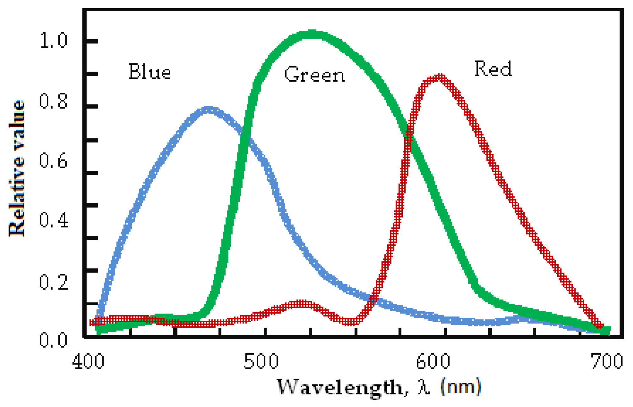
The use of a smartphone to analyze spectral responses of luminescent materials usually performed with standard spectrometers requires a comparison of their spectral responses. The spectral response of a spectrometer is determined by the spectral sensitivity curve of the photodiode array and the spectral efficiency of the diffraction grating. The spectral response of the smartphone is determined by the transmission spectra of the RGB pixels, an example of which for Android smartphones is presented [15] in Figure 4. Figure 5a shows the experimental setup that allows for the simultaneous measurement of the responses of the spectrometer and smartphone (Samsung A51) with a 1000 l/mm transmission grating. White light with power P is emitted into a monochromator whose output is varied from 390 nm to 700 nm, and further emitted into a 50%/50% optical fiber splitter. One signal IOO(λ) is observed by means of the spectrometer (OO—Ocean Optics) and the other IMP(λ) by the mobile phone. We then calculate the ratio as follows:
r ( λ , P ) = I M P ( λ , P ) I O O ( λ , P ) for   P = const
The wavelength dependence r(λ) is shown in Figure 5b. It is quite uneven and exhibits some minima at the boundary of the RGB spectral ranges, corresponding to the intersection of the RGB transmission spectra in Figure 4.
To test if the smartphone linearly responds to the level of the signal, we replace the constant-power, laser-driven white light source with a white LED whose output power can be varied. We measure the spectra with both the spectrometer and mobile phone, and from each spectrum we calculate the power in the blue, green, and red spectral ranges indicated in Figure 5b. In Figure 5c, we show the white LED spectrum as measured by the spectrometer (thin red line) and the mobile phone (thick blue line). The thin dotted line is a multiple of the ratio in Figure 5b and shows that the distortions of the LED spectrum as measured by the spectrometer are caused by the specific RGB transmission filters of the smartphone. Figure 5d presents the ratio r(P) as a function of the optical power of the LED source for the three spectral ranges of blue, green, and red, and as a function of the total power as measured by the spectrometer. We see that as the optical power of the detected light increases, the intensity detected by the smartphone compared to that measured by the spectrometer decreases with the signal level, i.e., the smartphone signal tends to reach saturation following a power law of the type
r ( P ) = R . P p
where the coefficient R and the power p depend on the pixel color. The effect is stronger for the blue part of the spectrum and the weakest for the red part, which is evident from Figure 5c where we see that the blue peak appears much weaker with the smartphone than the green and red components. The smartphone thus distorts the shape of the detected spectrum and is signal-power-dependent. These distortions depend on the particular mobile phone model and create the necessity for calibration [16].

4.2. Measurements without a Lens

A low-cost transmission sheet grating with 1000 lines/mm is placed in front of the smartphone’s camera. The spectra measured by the smartphone are taken simultaneously with those measured by the spectrometer.
Figure 6 shows stacks of photos of observed spectra taken by a smartphone with excitation varying from 220 nm to 420 nm. All images are processed using a custom-made software that is written in Python and makes use of the Numpy, Panda, MatplotLib, and OpenCV frameworks. The total intensity of the vertical column of activated pixels is presented as a function of the horizontal pixel position. For the purposes of wavelength calibration, the position of the zero-th order is considered λ0 = 0 nm. Excitation wavelengths above 400 nm appear on the screen of the smartphone as shown in Figure 6a,b and can be used to plot the dependence λ(N), where N is the number of the pixel corresponding to the wavelength λ. The dependence is linear as seen in Figure 6c, and we can write it in the following form:
λ ( N ) = Λ 0 + S N N
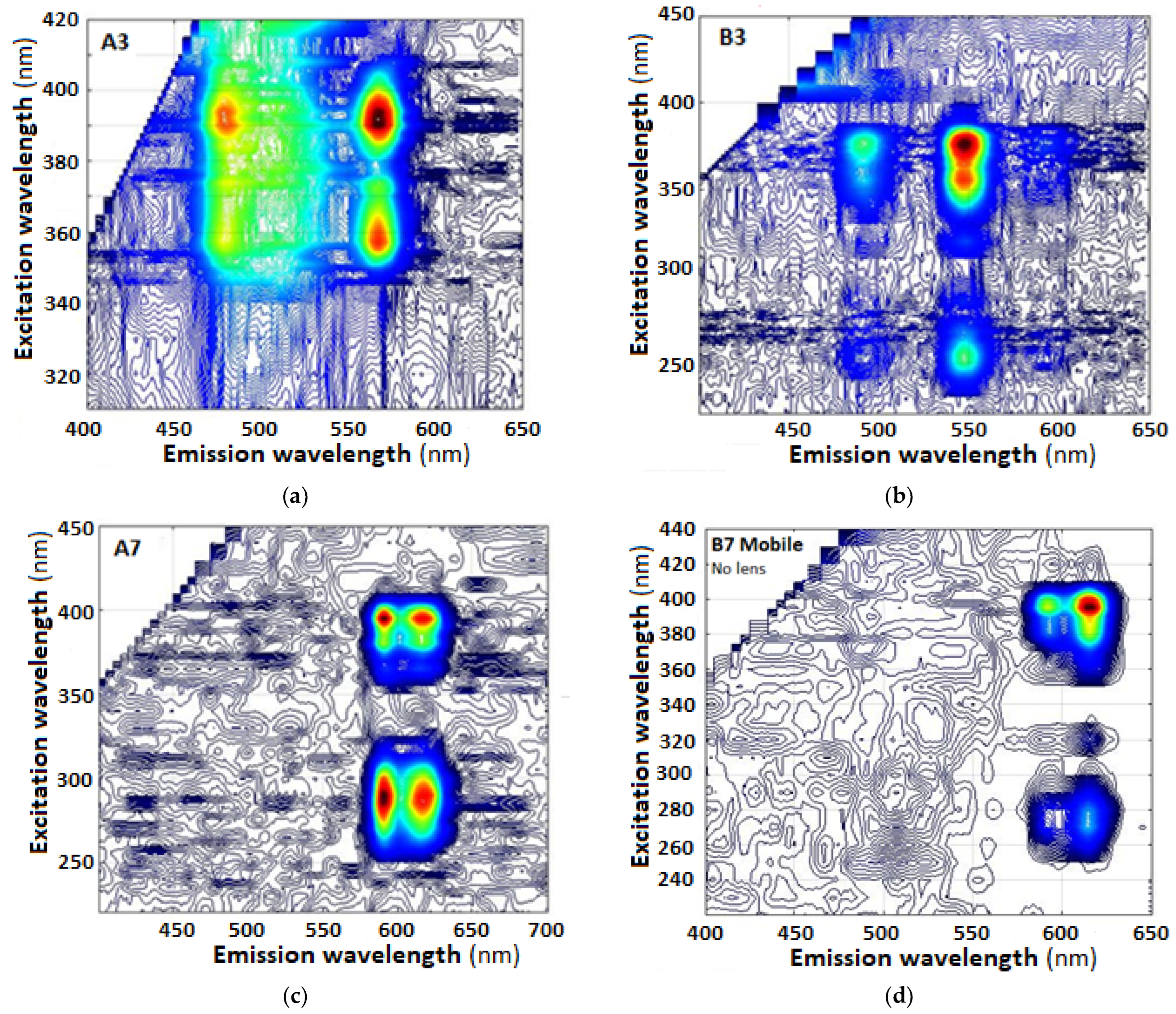
The factor D = 1/SN is the dispersion of the smartphone spectrometer and depends on the magnification of the camera. For the spectrum images of B4 (Figure 6b), SN = 0.1973 nm/pxl, so the dispersion is D = 5.0684 pixels/nm or D ≈ 5 pixels/nm. Figure 7a–f shows the topographic view of the 3D excitation–emission spectra of samples A3, B4, A7, B8, A10, and B10, which correspond to the spectra in Figure 2 for the same samples.
Figure 2 and Figure 7 present the 3D spectra of (a) A3, (c) A7, (e) A8 and (g) A10 measured by the Ocean Optics spectrometer (OO) and of (b) B4, (d) B7, and (f) B8 and (h) B10 measured by the mobile phone (MP). A comparison between these 3D spectra allows for the enumeration of the following observations:
(i)
The smartphone accurately reproduces the narrow excitation–emission band within the 400 nm to 700 nm mobile phone sensitivity range and allows for the identification of the emission maxima of the samples in spite of the distortions mentioned in Section 4.1.
(ii)
The smartphone cuts off all spectral content above 700 nm, and above 650 nm, weak maxima are practically undetectable, which is a disadvantage. At the same time, it efficiently eliminates the spectra of the excitation light for wavelengths ≤ 395 nm and strongly reduces them up to 405 nm, which is an important advantage for fluorescence measurements.
(iii)
The smartphone modifies the proportions between neighboring peaks, which means that to identify the sample, the spectrum as measured by a smartphone must be known, especially in the case of ratiometric measurements.
(iv)
The smartphone efficiently cuts off the emission from the excitation sources in the UV range, as evidenced by Figure 6a,b, in which range the spectrometer may be saturated.

4.3. Measurements with a Lens

In this case, the setup is modified by adding an optional short-focal-length lens in combination with a 1 mm-diameter diaphragm. The unit is placed on the sample and collects light from a larger solid angle. Thus, the signal level is increased. However, due to the magnification, the size of the sample is enlarged and occupies a larger number of pixels on the screen of the mobile phone.
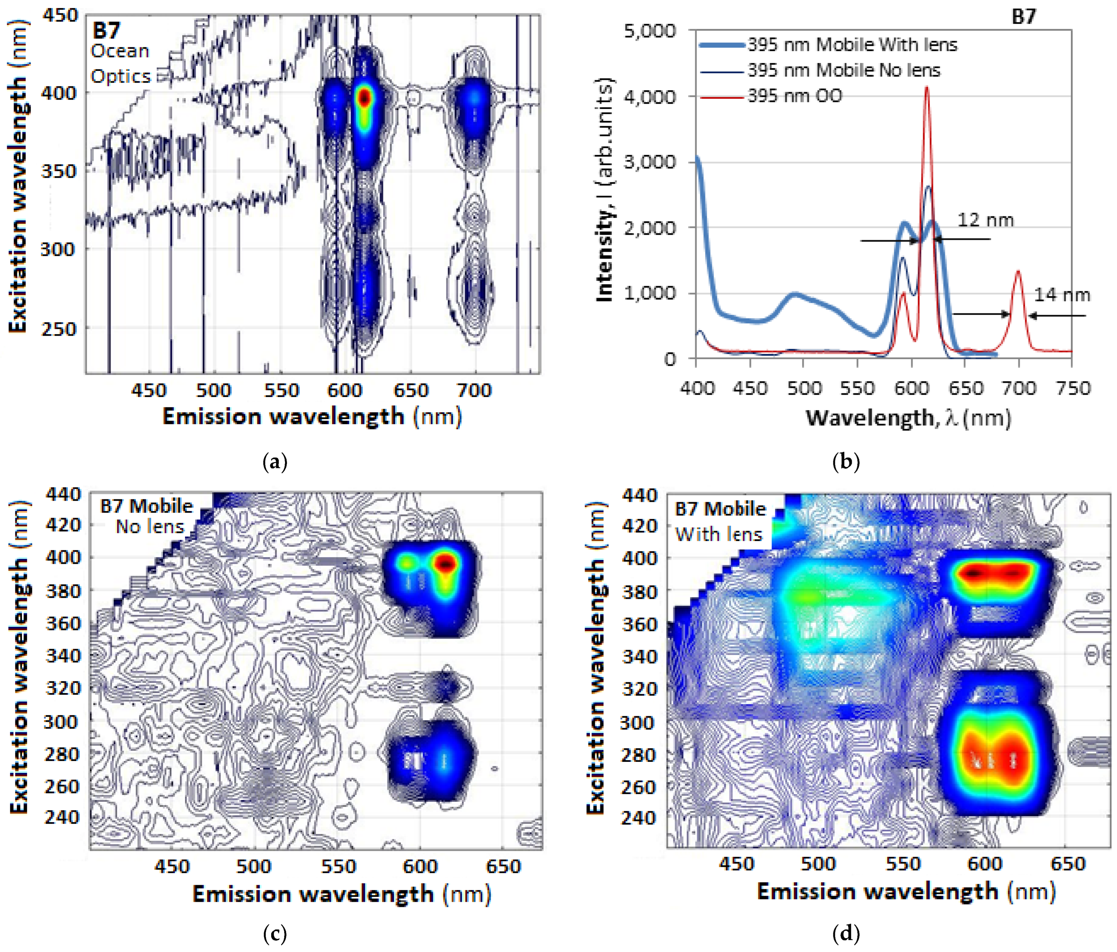
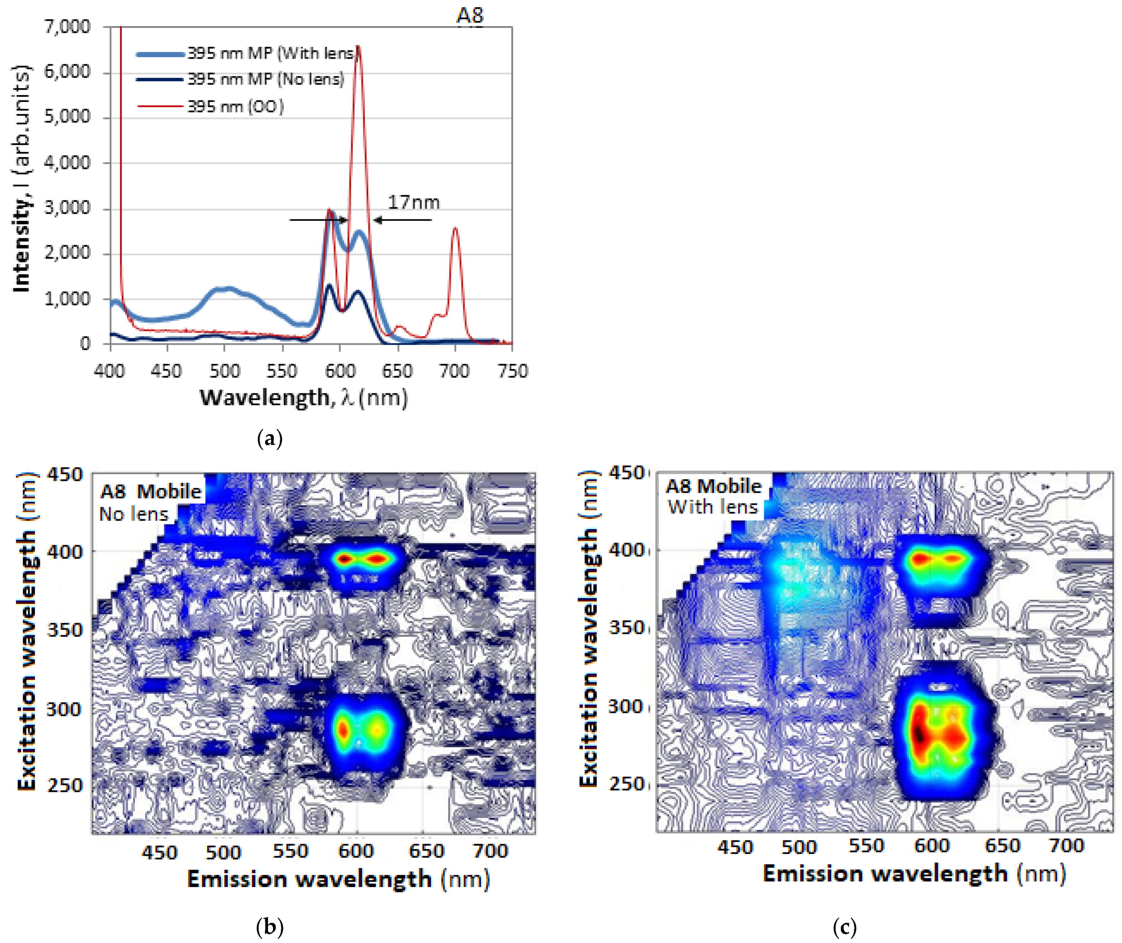
To illustrate the effect of the lens on the measured spectrum with an excitation wavelength close to the maximum excitation efficiency, which for the samples under study is in the range between 378 and 400 nm, we present in Figure 8 the fluorescence spectra of sample B7 as observed by the spectrometer and by a smartphone with and without a lens. We see that the visibility of the two peaks is the highest when measured by a spectrometer, lower when measured by the smartphone without lens, and worst when measured by a lens. The reason for the reduction in the visibility of the peaks is the poorer resolution, because unlike the spectrometer, no narrow slit is used to reduce the size of the image whose spectrum is being observed. A second reason is the saturation of the signal in the smartphone, as demonstrated in Figure 5d.
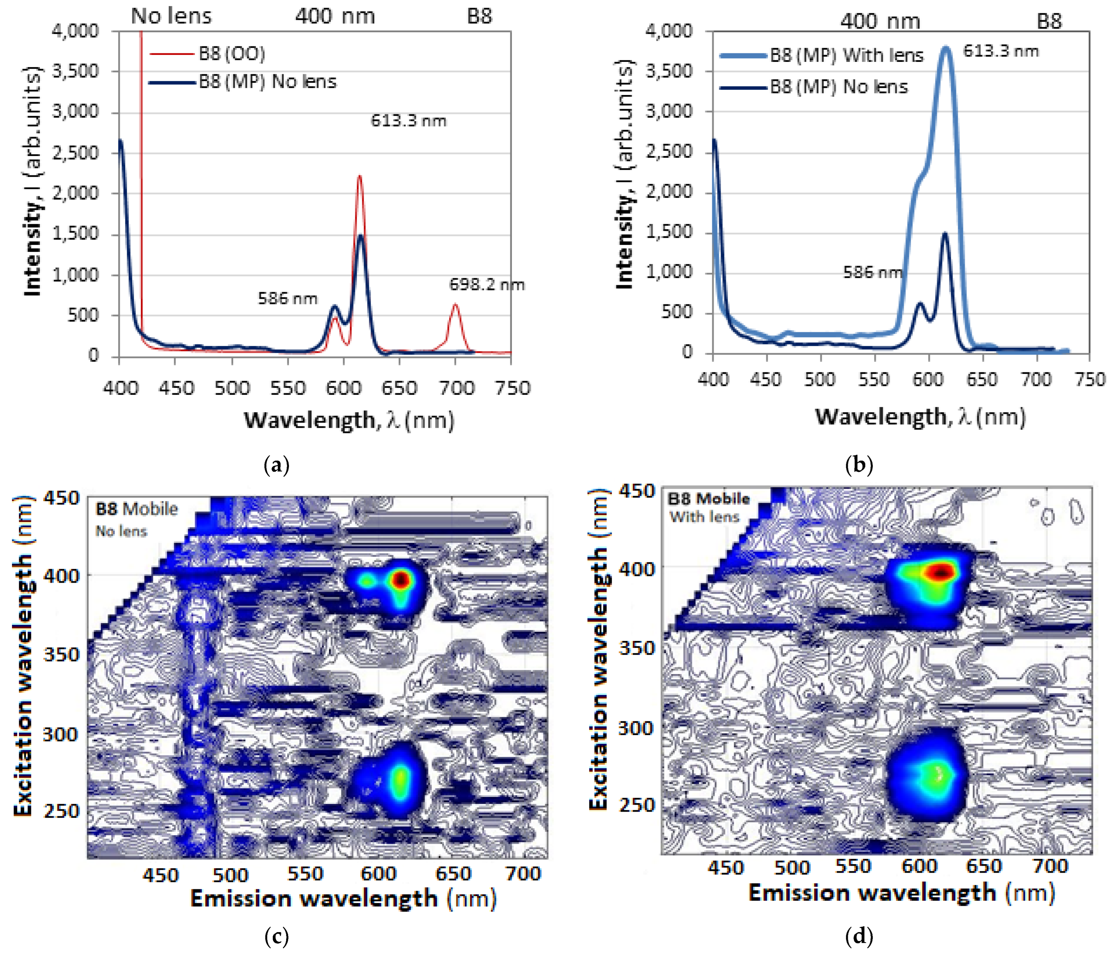
When a lens is used, two effects are clearly observed. First, since the short-focal-length lens gathers light from a wider angle, the signal level is increased. Second, weak signals from the background and stray light become visible. The mobile phone, however, has a higher transmission in the green range as evidenced by Figure 4, which leads to the appearance of the weaker broader maxima around 500 nm as in Figure 8 and Figure 9. Their presence is conditional on the existence of parasitic glares and background light and requires additional study.
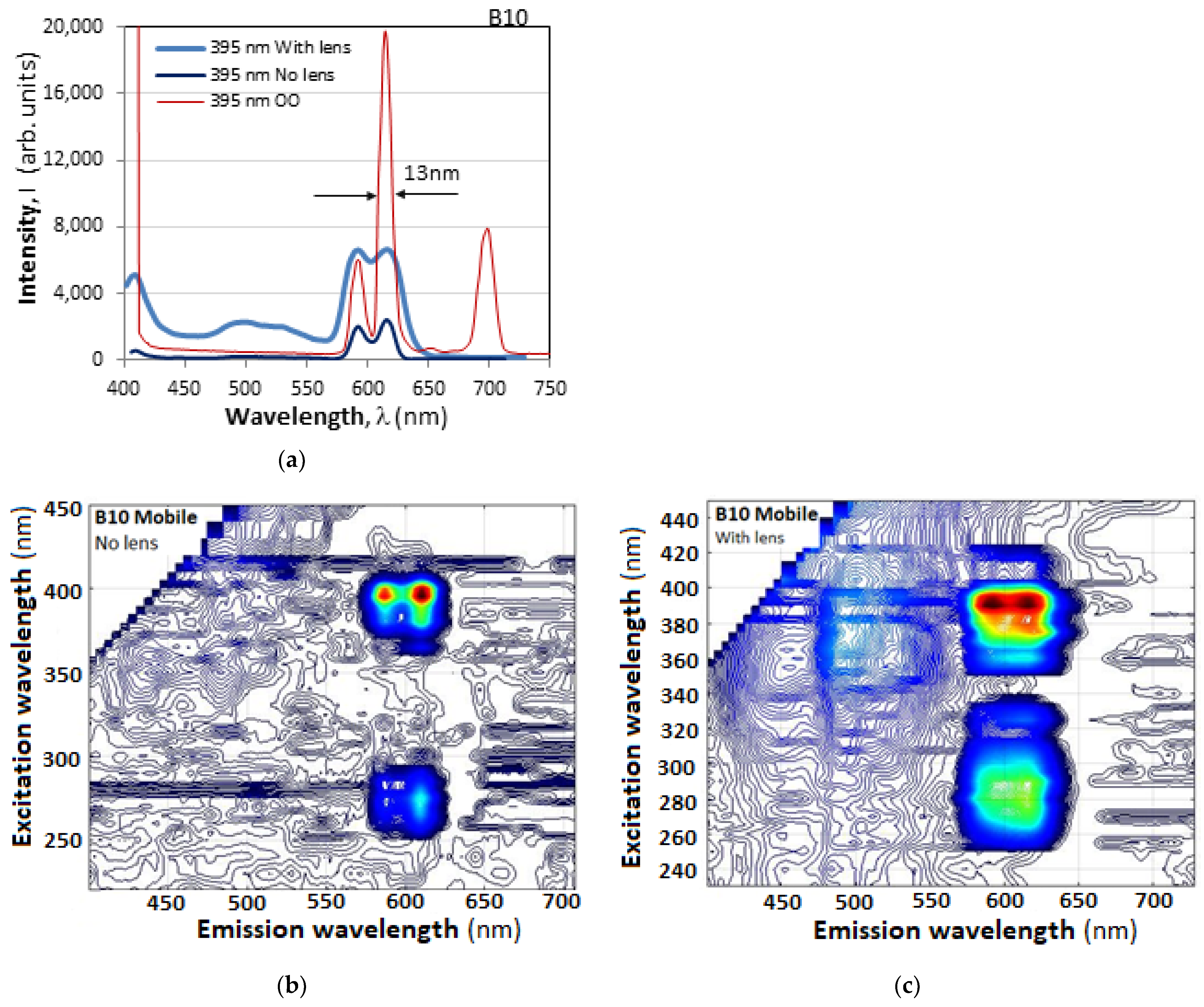
The same observations, to a different degree, are valid for samples B8 and B10 shown in Figure 10 and Figure 11. In all cases, what is important for the purposes of this study is the possibility of clearly outlining and identifying the strong narrow excitation–emission spectra, which proves to be successful.
In all cases, the RGB pixel filters strongly reduce the peak of the excitation light at wavelengths ≤ 400 nm, which is an important advantage. The effects of the additional magnification lens can be summarized as follows:
(i)
The lens increases the level of the signal at the expense of reduced visibility and resolution.
(ii)
The increased signal level may cause the appearance of spectral noise in the blue–green range because of background light and glares.

5. Measurements with LED Sources

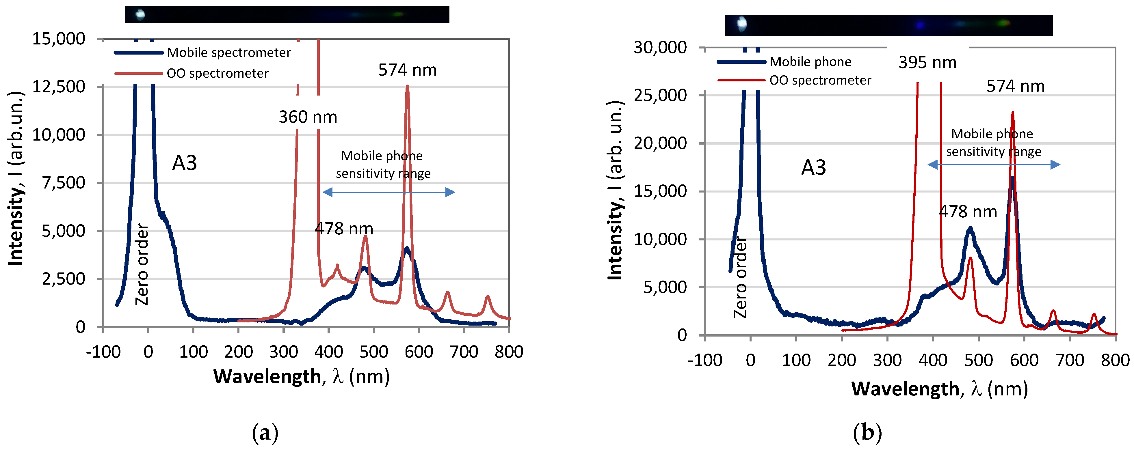
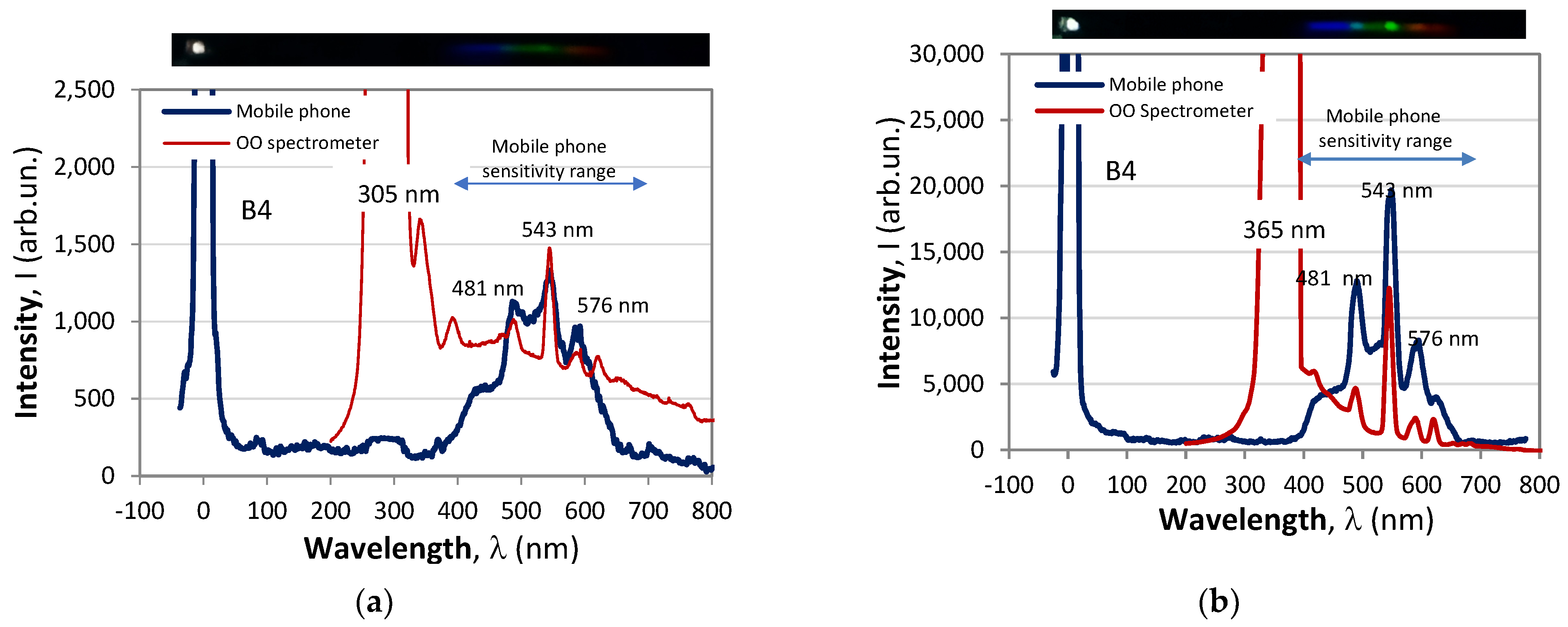
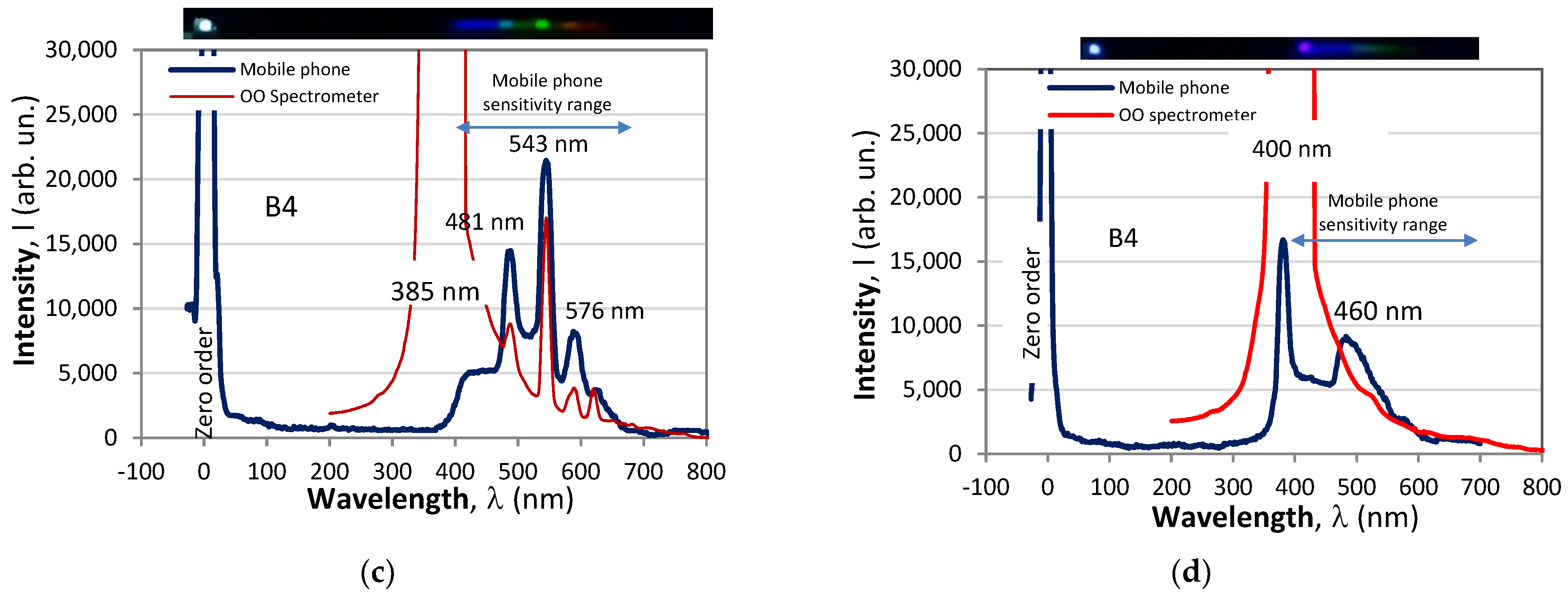
For the majority of applications of borates with smartphone interrogation, the excitation source is an LED or a laser diode, rather than a monochromator. In this case, the possible excitation wavelengths are limited in number, and the excitation wavelength of maximum intensity may be different from that of maximum efficiency. This may be a serious problem, since the excitation bandwidth of high efficiency is of the order of the bandwidth of an LED, i.e., 15–20 nm. To compare the monochromator with LED excitation, we carry out measurements with UV LEDs whose maximum intensity wavelength is close to the maximum efficiency wavelength. Some of the results are presented in Figure 12, Figure 13 and Figure 14.
The spectra at the same LED excitation measured by the spectrometer and the mobile phone are presented in the same graphs, which allows for the formulation of the following observations:
(i)
The mobile phone outlines the characteristic narrow-emission spectral peaks of the samples under study.
(ii)
The mobile phone very efficiently blocks the UV excitation light, and in the case when the excitation wavelength is close to the emission peak, the latter is still detectable (see Figure 14d).
(iii)
The mobile phone strongly attenuates all peaks above 670 nm.

6. Arrays of Fluorescent Markers

Since the smartphone efficiently blocks UV excitation and allows for the identification of the narrow-band spectral signatures of the different samples, we now investigate the possibility of discerning markers of these samples arranged in linear arrays so as to form specific patterns.

6.1. Basic Arrangement

Figure 15 presents the experimental arrangement to simultaneously illuminate a large number of samples. A glass cylinder is placed in front of the UV LED to form a thin line, which simultaneously excites up to 10 samples placed in holes of 1 mm in diameter in an opaque plate. Since the intensity of the light focused into a line is not uniformly distributed, we take the spectra of the samples in two groups of five.

6.2. Results and Comments

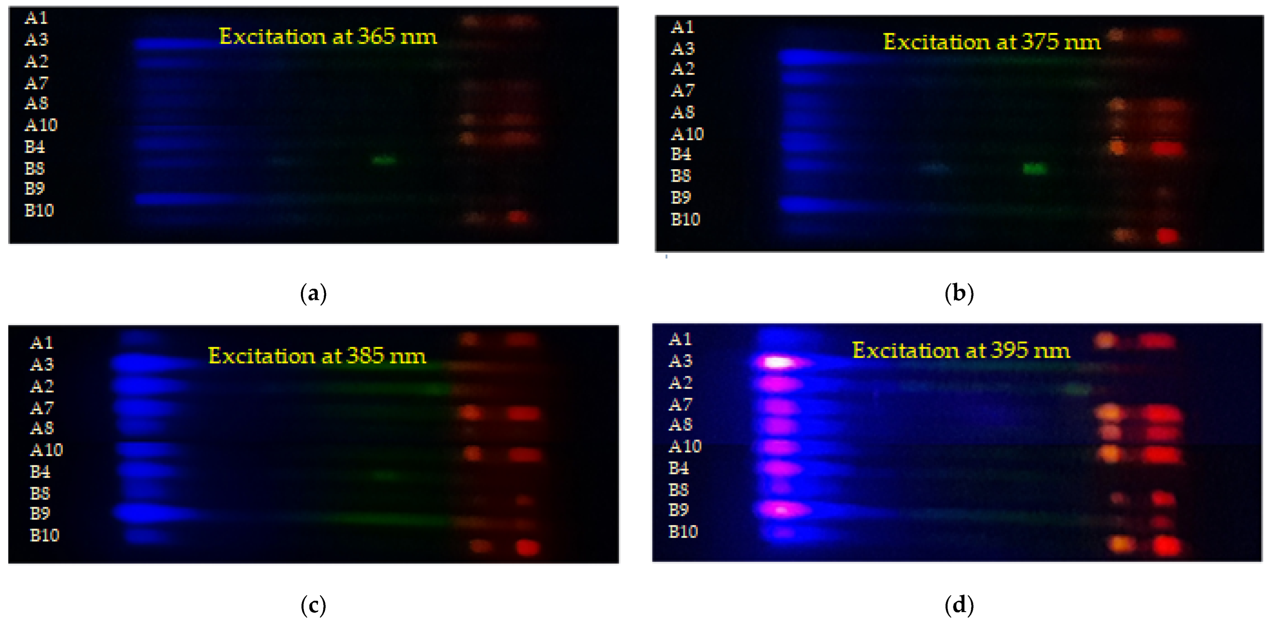
Using the arrangement in Figure 15, we perform a simultaneous observation of the spectra of 10 of the samples, namely A1, A2, A3, A7, A8, A10, B4, B5, B9, and B10, arranged in a column. Figure 16a–d shows the spectra under 365nm, 375 nm, 385 nm, and 395 nm LED excitation. We note that when the excitation wavelength is varied, the observed spectral arrays are noticeably changed. The strongest signal is for the 385 nm and 395 nm excitations and the wings of the excitation wavelengths are more pronounced than at 365 nm and 375 nm. These spectra suggest that in the case of a two-level encoding scheme in which a “0” (black) is attributed to a signal below a given threshold and a “1” (white) to a signal above the threshold, the four colored patterns in Figure 16 would appear as different black-and-white 2D spatial patterns.
The research performed and the results obtained outline the need for some further research in view of the possible applications related to luminescent markers using remote sensing and interrogation. In the first place, the deformations of the spectral response compared to those of spectrometers must be studied for a variety of makes of smartphones and for different levels of signals. Second, a more detailed study on the use of additional lenses to augment signal level must be performed, as well as on the effect of the internal magnification of the smartphone camera on the measured spectrum. Third, the spectral responses in the case of arrays of fluorescent materials, and last, the improvement of the synthesis technology to obtain more efficient luminescence with more repeatable characteristics must all be studied.

7. Conclusions

The experiments and the analysis performed allow for the formulation of the following conclusions:
C1.
The synthesized rare-earth-doped lanthanum and aluminum borates are characterized by spectra that are as narrow as Δλ’ = 15 nm for the excitation and Δλ = 12 nm FWHM for the emission bandwidths, which are comparable to the emission band when LEDs are used as excitation sources.
C2.
The particular peaks of maximum excitation–emission wavelengths depend on the particular rare earth dopants and their combinations, and in the general case, lanthanum borates demonstrate a higher luminescence intensity compared to the aluminum borates for the orange–red emission peaks (586 nm/613 nm) and comparable intensities to the green peak (543 nm).
C3.
Because the maximum efficiency excitation band Δλ’ is practically the same as the LED emission bandwidth, the studied La and Al borates are particularly appropriate for UV LED excitation in the 375 nm–395 nm range to serve as selective fluorescent markers for a number of applications.
C4.
Smartphones equipped with a low-cost transmission diffraction grating can efficiently be used for the contactless detection of the synthesized materials.
C5.
Because of their RGB filter characteristics, smartphones efficiently attenuate the excitation outside the visible range and are therefore useful in the case when excitation in the infrared is based on upconversion [26].
C6.
Compared to spectrometers, smartphones exhibit a rather non-uniform spectral sensitivity curve featuring several maxima as well as a power-law-diminishing intensity ratio.
C7.
Smartphones allow for the plotting of 3D excitation–emission spectra and accurately identify the individual excitation–emission peaks of the particular samples. However, as the spectral sensitivity of the smartphone is determined by the transmission spectra of its RGB filters and the diminishing smartphone-to-spectrometer intensity ratio, the relative intensities of the different peaks may differ from those measured by a standard spectrometer.
C8.
The use of an additional short-focal-length lens in combination with the smartphone increases the intensity of the detected signal since more light is gathered, but on the other hand, it reduces the resolution and contrast in the detection of closely spaced peaks. It may also create some spectral noise in the green part of the spectrum.
C9.
Unlike the standard spectrometer, the smartphone allows for the simultaneous detection of the spectra of arrays of the studied fluorescent markers, of which the spatial distribution will appear different depending on the particular excitation.

Author Contributions

Conceptualization, K.H., I.P.K. and T.A.E.; methodology, K.H. and T.A.E.; software, D.B.; validation, I.P.K. and T.A.E.; formal analysis, T.A.E.; investigation, K.H., S.F. and T.A.E.; resources, K.H. and I.P.K.; data curation, D.B.; writing—original draft preparation, K.H. and T.A.E.; writing—review and editing, I.P.K.; visualization, D.B. and S.F.; supervision, I.P.K. and T.A.E.; project administration, I.P.K.; funding acquisition, T.A.E. All authors have read and agreed to the published version of the manuscript.

Funding

This research was funded by NSERC (Natural Sciences and Engineering Research Council) Discovery Grant, Canada.

Data Availability Statement

The raw data supporting the conclusions of this article will be made available by the authors on request.

Conflicts of Interest

The authors declare no conflicts of interest.

References

  1. Abacı, Ö.C.H.; Mete, E.; Esenturk, O.; Yılmaz, A. Tunable optical properties and DFT calculations of RE3+ codoped LaBO3 phosphors. Opt. Mater. 2019, 98, 109487. [Google Scholar] [CrossRef]
  2. Cornejo, C.R. Luminescence in Rare Earth Ion-Doped Oxide Compounds (Ch.3). In Luminescence—An Outlook on the Phenomena and Their Applications; Thirumalai, J., Ed.; InTech: New Delhi, India, 2016; pp. 33–63. [Google Scholar]
  3. Richardson, F.S. Terbium (III) and europium (III) ions as luminescent probes and stains for biomolecular systems. Chem. Rev. 1982, 82, 541–552. [Google Scholar] [CrossRef]
  4. Nagpure, P.A.; Bajaj, N.S.; Sonekar, R.P.; Omanwar, S.K. Synthesis and luminescence studies of novel rare earth activated lanthanum pentaborate. Indian J. Pure Appl. Phys. 2011, 49, 799–802. [Google Scholar]
  5. Ike, P.O.; Folley, D.E.; Agwu, K.K.; Chithambo, M.L.; Chikwembani, S.; Ezema, F.I. Influence of dysprosium doping on the structural, thermoluminescence and optical properties of lithium aluminium borate. J. Lumin. 2021, 233, 117932. [Google Scholar] [CrossRef]
  6. Ike, P.O.; Nwanya, A.C.; Agwu, K.K.; Ezema, F.I. Optical and thermoluminescence response of rare earth activated aluminium borate crystals. Opt. Mater. 2022, 127, 112263. [Google Scholar] [CrossRef]
  7. Fu, L.; Zhao, X.; Meng, Z.; Zhang, J.; Chu, G. Characterization and luminescent properties of lanthanum borate prepared by solution combustion method. Mater. Sci. Eng. B 2023, 291, 116362. [Google Scholar] [CrossRef]
  8. Zhu, Q.; Fan, Z.; Li, S.; Li, J.-G. Implanting bismuth in color-tunable emitting microspheres of (Y, Tb, Eu)BO3 to generate excitation- dependent and greatly enhanced luminescence for anti-counterfeiting applications. J. Asian Ceram. Soc. 2020, 8, 542–552. [Google Scholar] [CrossRef]
  9. Lee, J.K.; Hua, Y.; Yu, J.S. High-quality reddish-orange-emitting Sr6Y2Al4O15:Eu3+ phosphors for solid-state lighting and anti-counterfeiting applications. Ceram. Int. 2024, 50, 484–494. [Google Scholar] [CrossRef]
  10. Ingle, J.T.; Sonekar, R.P.; Omanwar, S.K. Combustion synthesis and superior photo-luminescence from rare earth doped (Eu, Tb) lanthanum borates phosphors for display. J. Mater. Sci. Mater. Electron. 2016, 27, 10735–10741. [Google Scholar] [CrossRef]
  11. Paterson, A.S.; Raja, B.; Mandadi, V.; Townsend, B.; Lee, M.; Buell, A.; Vu, B.; Brgoche, J.; Willson, R.C. A low-cost smartphone-based platform for highly sensitive point-of-care testing with persistent luminescent phosphors. Lab Chip 2017, 17, 1051–1059. [Google Scholar] [CrossRef]
  12. Ramalho, J.F.C.B.; António, L.C.F.; Correia, S.F.H.; Fu, L.S.; Pinho, A.S.; Brites, C.D.S.; Carlos, L.D.; André, P.S.; Ferreira, R.A.S. Luminescent QR codes for smart labelling and sensing. Opt. Laser Technol. 2018, 101, 304–311. [Google Scholar] [CrossRef]
  13. Shahvar, A.; Shamsaei, D.; Saraji, M. A portable smartphone-based colorimetric sensor for rapid determination of water content in ethanol. Measurement 2020, 150, 107068. [Google Scholar] [CrossRef]
  14. Xu, J.; Zhang, Y.; Li, Y.; Zhao, D.; Zhang, L.; Bi, N.; Gou, J.; Zhao, T.; Jia, L. Multifunctional dual-channel fluorescent nanoprobe for visual fluorescence detection of pathogenic bacteria and excessive antibiotics in food safety. J. Lumin. 2024, 266, 120303. [Google Scholar] [CrossRef]
  15. Tominaga, S.; Nishi, S.; Ohtera, R. Measurement and Estimation of Spectral Sensitivity Functions for Mobile Phone Cameras. Sensors 2021, 21, 4985. [Google Scholar] [CrossRef]
  16. Pituła, E.; Koba, M.; Smietana, M. Which smartphone for a smartphone-based spectrometer? Opt. Laser Technol. 2021, 140, 107067. [Google Scholar] [CrossRef]
  17. Swapna, K.; Mahamuda, S.; Rao, A.S.; Jayasimhadri, M.; Shakya, S.; Prakash, G.V. Tb3+ doped Zinc Alumino Bismuth Borate glasses for green emitting luminescent devices. J. Lumin. 2014, 156, 180–187. [Google Scholar] [CrossRef]
  18. Murthy, K.V.R.; Sai Prasad, A.S.; Rao, M.R. Luminescence Characteristics of Eu and Tb Doped YGdBO3 Phosphor. Phys. Procedia 2012, 29, 70–75. [Google Scholar] [CrossRef]
  19. Pisarski, W.A.; Pisarska, J.; Dominiak-Dzik, G.; Mączka, M.; Ryba-Romanowski, W. Compositional-dependent lead borate based glasses doped with Eu3+ ions: Synthesis and spectroscopic properties. J. Phys. Chem. Solids 2006, 67, 2452–2457. [Google Scholar] [CrossRef]
  20. Pisarska, J.; Kos, A.; Sołtys, M.; Żur, L.; Pisarski, W.A. Energy transfer from Tb3+ to Eu3+ in lead borate glass. J. Non-Cryst. Solids 2014, 388, 1–5. [Google Scholar] [CrossRef]
  21. Van Do, P.; Ngoc, T.; Ca, N.X.; Thanh, L.D.; Thanh Nga, P.T.; Chung Thuy, T.T.; Van Nghia, N. Study of spectroscopy of Eu3+ and energy transfer from Ce3+ to Eu3+ in sodium-zinc-lead-borate glass. J. Lumin. 2020, 229, 117660. [Google Scholar]
  22. Ebendorff-Heidepriem, H.; Ehrt, D. Formation and UV absorption of cerium, europium and terbium ions in different valencies in glasses. Opt. Mater. 2000, 15, 7–25. [Google Scholar] [CrossRef]
  23. Sankara, R.; Subba Rao, G.V. Eu3+ Luminescence, Ce4+→Eu3+ Energy Transfer, and White-Red Light Generation in Sr2CeO4. J. Electrochem. Soc. 2000, 147, 2773. [Google Scholar] [CrossRef]
  24. Wantana, N.; Kaewnuam, E.; Chanlek, N.; Kim, H.J.; Kaewkhao, J. Influence of Gd3+ on structural and luminescence properties of new Eu3+-doped borate glass for photonics material. Radiat. Phys. Chem. 2023, 207, 110812. [Google Scholar] [CrossRef]
  25. Hristova, K.; Kostova, I.; Eftimov, T.; Tonchev, D. Synthesis and Luminescent Characteristics of Yttrium, Aluminium and Lanthanum Borates Doped with Europium Ions (Eu3+). Bulg. Chem. Commun. 2024. accepted for publication. [Google Scholar]
  26. Zhu, D.; Guo, K.; Yao, J.; Duan, B.; Wu, Y.; Li, Y.; Wang, F.; Liu, T.; Hu, J. The single near-infrared upconversion luminescence of a novel KYb (MoO4)2: Er3+ phosphor for the temperature sensing. J. Mol. Struct. 2024, 1310, 138304. [Google Scholar] [CrossRef]
Figure 1. Experimental setup: (a) basic arrangements for the measurement of the 3D excitation–emission spectra of the samples using a standard optical fiber spectrometer; (b) side view of the arrangement from (a) with a smartphone camera equipped with a sheet transmission diffraction grating (1000 L/mm) to observe the spectrum.
Photonics 11 00434 g001
Figure 2. Topographic views of the excitation–emission fluorescence spectra measured by an Ocean Optics spectrometer of synthesized samples from the A (La2O3 + H3BO3) and B (Al2O3 + H3BO3) groups: (a) A3—(Dy2O3); (b) B4—(TbF3); (c) A7 and (d) B7—(Eu2O3 + TbF3); (e) A8 and (f) B8—(Eu2O3 + Ce(SO4)2 × 4 H2O); (g) A10 and (h) B10—(Eu2O3 + Gd2O3). The red rectangles show the wavelength ranges within which the spectra were measured with the smartphone.
Photonics 11 00434 g002aPhotonics 11 00434 g002b
Figure 3. Excitation efficiency spectra and bandwidths of samples: (a) A3 and (b) A10.
Photonics 11 00434 g003
Figure 4. The transmission spectra of the R, G, and B pixels of an Android smartphone [15].
Photonics 11 00434 g004
Figure 5. Spectrometer vs. smartphone comparison: (a) an auxiliary experimental setup to compare spectrometer and smartphone responses; (b) the spectral dependence of the ratio r(λ) between the signal from the mobile phone to that of the spectrometer for a given signal level P(λ); (c) a white LED spectrum as measured by a spectrometer (OO) and a smartphone (MP); (d) the r(P) dependence for each of the R, G, and B spectral ranges.
Photonics 11 00434 g005
Figure 6. Stacked images of the spectra of samples (a) A3 and (b) B4 measured by the smartphone at excitations from 220 nm to 420 nm; (c) the λ(N) plot for B4.
Photonics 11 00434 g006
Figure 7. Topographic view of the excitation–emission fluorescence spectra of the two samples in Figure 3, taken by a smartphone: (a) A3; (b) B4; (c) A7; (d) B7; (e) A8; (f) B8; (g) A10 and (h) B10.
Photonics 11 00434 g007aPhotonics 11 00434 g007b
Figure 8. Illustration of the effect of using a magnifying lens for B7: (a) topographic view of the 3D excitation–emission spectra taken by a mobile with a lens; (b) comparison between the spectra of B7 excited at 395 nm taken by a spectrometer (Ocean Optics—OO) and a mobile phone with and without a lens. (c) sample B7 without lens and (d) sample B7 with lens.
Photonics 11 00434 g008
Figure 9. Illustration of the effect of using a magnifying lens for A8: (a) topographic view of the 3D excitation–emission spectra taken by a mobile phone with a lens; (b) comparison between the spectra of A8 excited at 395 nm taken by a spectrometer (OO) and a mobile phone with and without a lens; (c) same as (b) but with lens.
Photonics 11 00434 g009
Figure 10. Illustration of spectral resolutions for B8: (a) Ocean Optics spectrometer spectrum vs. mobile phone spectrum without a lens; (b) mobile phone spectra with and without an additional lens; (c) topographic view of the 3D excitation–emission spectra of sample B8 taken by a mobile phone without lens; (d) same as (c) with a lens.
Photonics 11 00434 g010
Figure 11. (a) Comparison between the spectra of B10 excited at 395 nm taken by a spectrometer (OO) and by a mobile phone with and without a lens. (b) A topographic view of the 3D excitation–emission spectra taken by a mobile phone without a lens; (c) same as (b) but with a lens.
Photonics 11 00434 g011
Figure 12. Comparison between the spectra of samples (a) A3 and (b) B4 measured by an Ocean Optics spectrometer and a smartphone at wavelengths of maximum excitation efficiency.
Photonics 11 00434 g012
Figure 13. Comparison between the spectra measured by standard and mobile spectrometers for the A3 sample: (a) LED excitation at 360 nm; (b) LED excitation at 395 nm.
Photonics 11 00434 g013
Figure 14. Comparison between the spectra measured by standard and mobile spectrometers for the S 62 SS sample: (a) LED excitation at 305 nm; (b) LED excitation at 365 nm; (c) LED excitation at 385 nm; (d) LED excitation at 400 nm.
Photonics 11 00434 g014aPhotonics 11 00434 g014b
Figure 15. Experimental setup to simultaneously observe the spectra of fluorescent arrays.
Photonics 11 00434 g015
Figure 16. Experimental setup to simultaneously observe the spectra of fluorescent arrays.
Photonics 11 00434 g016
Table 1. List and notation of the synthesized samples.
La2O3 + H3BO3
Sample
Notation
REMol % of REsAl2O3 + H3BO3
Sample
Notation
REMol % of REs
A1Eu2O32B1Eu2O32
A2Sm2O32B2Sm2O32
A3Dy2O32B3--
A4--B4TbF32
A5Gd2O32B5--
A6Ce(SO4)2 × 4 H2O2B6Ce(SO4)2 × 4 H2O2
A7Eu2O3 + TbF32/1B7Eu2O3 + TbF32/1
A8Eu2O3 + Ce(SO4)2 × 4 H2O2/1B8Eu2O3 + Ce(SO4)2 × 4 H2O2/1
A9--B9Eu2O3 + Dy2O32/1
A10Eu2O3 + Gd2O32/1B10Eu2O3 + Gd2O32/1
A11Eu2O3 + Gd2O3 + TbF33/2/1B11--
A12--B12Eu2O3 + Dy2O3 + TbF33/2/1
Disclaimer/Publisher’s Note: The statements, opinions and data contained in all publications are solely those of the individual author(s) and contributor(s) and not of MDPI and/or the editor(s). MDPI and/or the editor(s) disclaim responsibility for any injury to people or property resulting from any ideas, methods, instructions or products referred to in the content.