1. Introduction
With the continuous increase in communication services, the transmission capacities of communication systems increase, and the capacities of single-mode fiber (SMF) communication systems approach the nonlinear Shannon limit. At present, few-mode fiber (FMF) communication technology based on mode division multiplexing (MDM) is a new expansion scheme used to break through the capacity limit of SMF systems [
1,
2,
3,
4,
5,
6]. Spatial division multiplexing fibers, represented by FMF and multi-core fiber (MCF), have become key innovation contenders in high-capacity transmission media, and will rapidly develop in the fields of long-distance high-capacity transmission and high-density access to data centers. Therefore, in light of the engineering deployment and large-scale application of FMF communication, one of the future SDM technologies, studying new FMF link fault detection technology is of great significance.
At present, fault detection of FMF links mainly follows the traditional fault detection concept of SMF. According to the implementation method of the detection signal, it can be divided into the optical time domain reflectometer (OTDR) [
7] and the optical frequency domain reflectometer (OFDR) [
8]. Among them, the OTDR is currently the most widely used type of fault detection technology in engineering. Its basic principle is to inject continuous optical pulses into the fiber link, and then measure and analyze the Rayleigh backscattering and Fresnel reflection power distribution curves carried by the fundamental mode LP
01. The precise location of any position, different types of events, and the loss characteristic measurement can be realized conveniently, in real time, and reliably. At present, many researchers are continuously conducting in-depth research on this technology and proposing optimization solutions, including chaotic OTDR technology [
9], single photon detector OTDR [
10], pulse coding modulation [
11], coherent OTDR [
12], linear optical sampling technology [
13], OTDR signal processing algorithm [
14,
15], etc. The measurement dynamic range, fault detection sensitivity, spatial resolution, and other parameters are greatly improved. However, it is very clear that due to the strong Fresnel reflections produced by the front fiber end faces, connectors, and other optical elements, the large power difference between these Fresnel reflections and backscattered Rayleigh leads to saturation of the photodetector (PD), resulting in a large dead zone in the single-mode OTDR system [
16]. Depending on the width of the input light pulse and the bandwidth of the photodetector, the dead zone is usually tens to hundreds of meters. In the dead zone, the traditional OTDR cannot provide reliable FMF link fault detection data, so it is a serious problem for OTDR-based FMF link fault detection applications.
At present, to reduce the influence of the dead zone caused by the end face of the front-end fiber, and so on, in practical engineering applications, we can reduce the length of the dead zone by cleaning the entrance connector to reduce the Fresnel reflection power. At times, this method may not completely eliminate the effect of the Fresnel reflection due to the quality of the optical fiber connector. In terms of technology, a transitional fiber (also known as a false fiber) is added between the OTDR and the optical fiber under-tested (FUT) during the actual fault detection. The false fiber is an optical fiber with a length ranging from 300 to 2000 m (the length can be selected according to the need). The dead zone of the front end falls in the transition false fiber, and the beginning end of the FUT falls within the linear stable region of the OTDR curve. This method makes the dead zone occur in the transition false fiber instead of the FUT. Therefore, the fault event at the beginning of the fiber link is easier to detect. However, this scheme reduces the maximum detection range of the OTDR. In addition, the connector between the transition fiber and the FUT may also create another dead zone at the beginning of the FUT. The OFDR method obtains the information in the fiber by measuring the frequency and phase information of the reflected light and performs high-precision measurements on the short fiber segment, without being affected by the dead zone caused by the pulse width in the traditional OTDR, effectively overcoming the dead zone problem in the OTDR. For example, Maxim E. Belokrylov et al. used advanced signal processing algorithms, digital frequency filtering, and empirical mode decomposition to achieve high spatial resolution [
17]. Fan Xinyu et al. proposed a hardware-adaptive OFDR phase noise compensation method, which has high computational efficiency and is easy to implement in hardware, achieving a dynamic range of 37.5 km and a spatial resolution of 7 cm [
18]. The OTDR based on time-dependent single photon counting has been reported to overcome dead zone limitations by detecting spontaneous Stokes–Raman signals, but this scheme cannot be used for detection and sensing applications that rely on Rayleigh backscattering [
19]. The chaos OTDR can overcome the blind spot problem in a traditional OTDR, to some extent, by using a chaotic laser signal and correlation detection technology [
20]. Yuan Mao et al. used the TMF-based OTDR to accurately perceive the location and frequency of vibration events located within the dead zone [
21]. Weicheng Chen et al. proposed a mode-coupled measurement system based on two photonic lantern schemes, which can eliminate the Fresnel reflection and the associated dead zone from the front facet of the fiber [
22].
Therefore, aimed at the problem of blind zone fault detection in FMF links, a dead-zone-free OTDR system is proposed based on the unique spatial mode dimension of FMF and the mode-selective photonic lantern multiplexer/demultiplexer (MUX/DEMUX). The detection optical pulse is injected through the fundamental mode LP
01 so that the Fresnel reflection from the fiber end surface only occurs on the LP
01 mode. The Rayleigh backscattering reflecting the fault distribution characteristics of the fiber link can be detected by the non-excited higher-order spatial mode. The experimental results show that—compared with the traditional OTDR LP
01 detection method—the proposed scheme can effectively solve the fault event detection in the blind area of FMF links. Compared with the TMF-based OTDR method for vibration sensing [
21], our proposed method can be used for the fault detection of FMF links, such as fusion splice, connector mismatch, and FMF break, by using the non-excited higher-order spatial modes LP
11a, LP
11b, LP
21a, LP
21b, and LP
02 Rayleigh backscattering amplitude. At the same time, the high sensitivity detection of fusion splice faults can be realized by using high-order spatial mode.
2. Experimental Principle
Figure 1 shows a comparison diagram of the traditional single-mode OTDR and the OTDR system based on higher-order spatial mode detection proposed in this paper. As shown in
Figure 1a, in a single-mode OTDR, the optical pulse is injected into the FMF through an SMF circulator. When the optical pulse carried by the fundamental mode LP
01 is transmitted forward along FMF, two different types of optical signals are transmitted in reverse. The first type of signal is reflected by the Fresnel reflected light signal at the connection of the circulator 2 port. The second type of signal is the elastic Rayleigh backscattering caused by the dielectric density fluctuation. The inelastic Brillouin scattering and Raman scattering are not considered in this study because they are not affected by the dead zone. Due to the mode coupling between FMF modes, Fresnel-reflected, and Rayleigh backscattering signals exist in the form of the fundamental mode LP
01 and other parts of the excited higher-order spatial mode. When reversely transmitted to the fiber circulator 2 port, the other higher-order spatial modes are coupled to the fundamental mode LP
01 or the loss disappears. Finally, the optical signal is still carried by the fundamental mode LP
01. The large power difference between Fresnel reflection and Rayleigh backscattering leads to saturation of the photodetector, resulting in a large dead zone in the single-mode OTDR system, as shown in
Figure 1a. Similarly, in a multimode OTDR-based system, the blind zone effect still exists because multiple spatial modes are excited and all modes are detected after reverse transmission.
The OTDR system based on the higher-order spatial mode proposed in this paper is shown in
Figure 1b. Compared with the traditional single-mode OTDR system, a mode MUX/DEMUX is added between the transmitter and the FMF under test. Assuming that the FMF used supports the propagation of N spatial modes, the mode MUX/DEMUX should have N input SMF ports and one FMF output port. Using the example shown in
Figure 1b for analysis, the optical pulse is injected into the MUX LP
01 mode port through the SMF circulator for spatial mode conversion and then injected into the FMF link. Due to the presence of spatial mode coupling between modes, the LP
01 mode energy is coupled to other higher-order spatial modes. When transmitting backward, the DEMUX converts the backscattering light of each spatial mode to the corresponding fundamental mode LP
01. The Fresnel reflections from inside the circulator and at the connector occur only in the LP
01 mode of the injected optical pulse, while the fault distribution of the reaction FMF link can be detected by Rayleigh backscattering of non-excited higher-order spatial modes. Therefore, the OTDR based on higher-order modes (LP
11a, LP
11b, LP
21a, LP
21b, etc.) can effectively avoid the influence of the dead zone, and fundamentally solve the dead zone problem of traditional OTDR. Similarly, any mode can also be used to inject detection optical pulses, while other spatial modes achieve dead-zone-free detection.
3. Experimental Results and Discussion
To verify the feasibility of the proposed scheme, the performance of the traditional single-mode OTDR system is compared with that of the OTDR system based on the higher-order spatial mode proposed in this paper. The experimental setup for FMF link fault detection based on the traditional single-mode OTDR is shown in
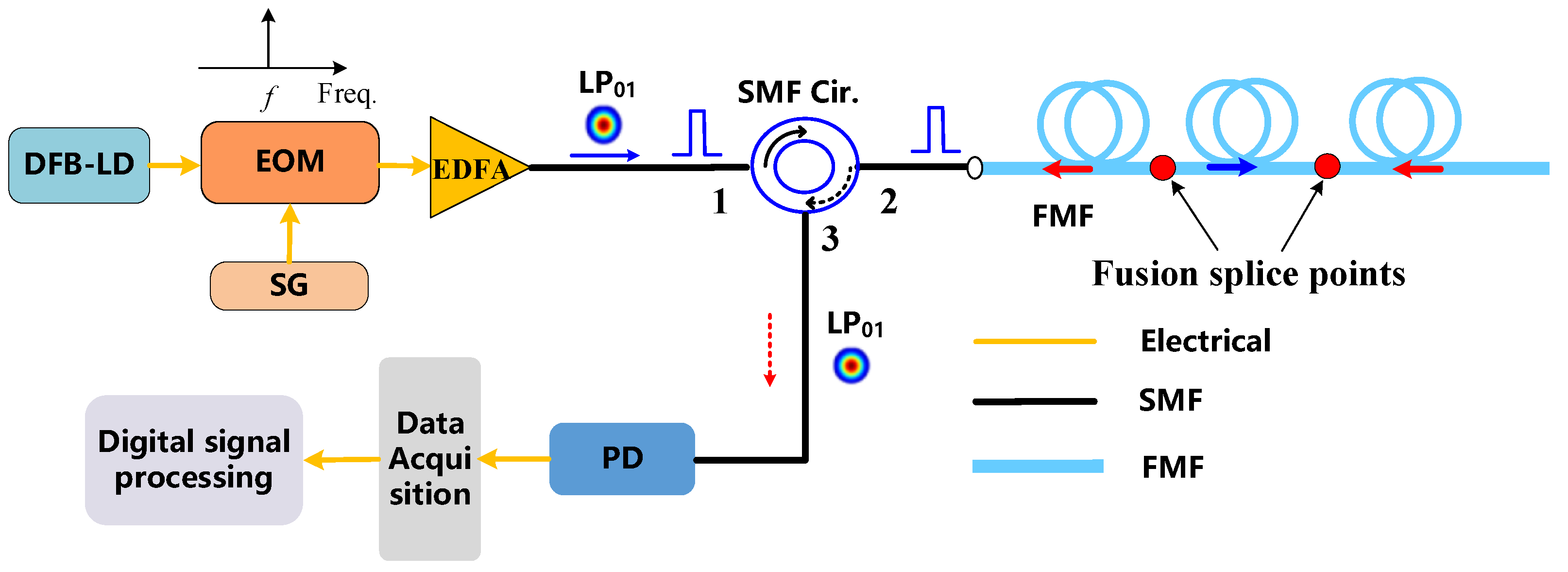
Figure 2. The distributed feedback laser (DFB) generates a 1550 nm continuous wave light, which is modulated by an electro-optic modulator (EOM) driven by a signal generator (SG) to generate an optical pulse signal with repetition frequency, f, and pulse width, T. The models of the DFB, SG, and EOM are Fby Photoelectric OSMPAC-15-3M, RIGOL DG1032, and Thorlabs LN56S, respectively. The modulated light pulse is amplified by the erbium-doped fiber amplifier (EDFA) and injected into the 3 km FMF link through the SMF circulator (SMF Cir.), and the fusion splice fault is introduced at the position 500 m away from the FMF input port. The fault event is set in the OTDR blind zone. At the same time, a fusion splice fault event is also introduced at 2.5 km of the FMF link. The core and cladding diameter of FMF under test are 13.28 μm and 125.26 μm, respectively. The mode field diameter and cutoff wavelength are 9.25 μm and 1325 nm, respectively. When the detecting optical pulse is transmitted along the FMF link, the Rayleigh backscattering signal returns to the single-mode fiber circulator through port 2 and enters the photodetector through port 3 for photoelectric conversion, and the electrical signal is sampled and averaged through the oscilloscope to further suppress the influence of noise on the detection result. Finally, digital signal processing is performed on the collected data, and the fault detection and location are performed by the Rayleigh backscattering curve of the LP
01 mode.
Based on the experimental device shown in
Figure 2, the FMF link fault detection is carried out. The SG output pulse signal with the repetition frequency of 10 kHz, pulse width of 1000 ns, and peak pulse power of 40 mw are set. The optical pulses are injected into the FMF link under test through the optical circulator. As shown in
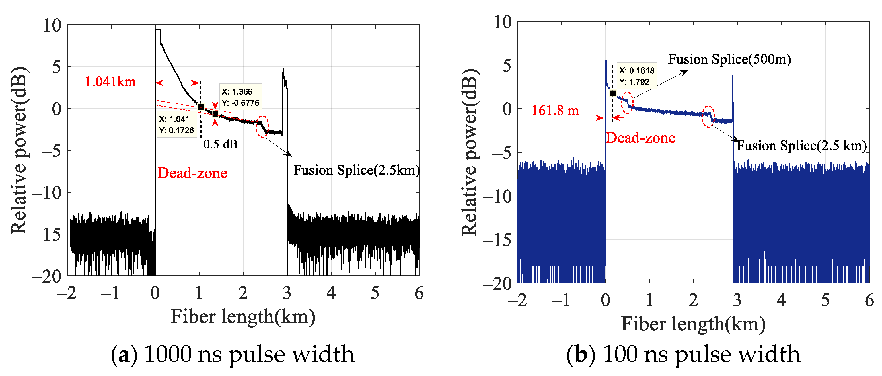
Figure 3, the fault detection results of the FMF link are based on the traditional single-mode OTDR under different optical pulse widths. At the beginning end of the FMF, it can be more clearly observed that the PD saturation is caused by excessive Fresnel reflection power from the fiber end face, the circulator interior, and the connector. The distance from the reflection point to the PD recovery to the backscattering level is approximately 0.5 dB, which means the attenuation blind zone is approximately 1041 m, as shown in
Figure 3a. Due to the existence of this blind area, the fusion splice fault at 500 m cannot be effectively identified. In contrast, the Rayleigh backscattering distribution can be observed after the dead zone, and the precise detection and location of the fusion splice fault at 2.5 km can be achieved. It can be seen that the traditional single-mode OTDR still has some defects in realizing the accurate detection and location of fault events in the blind zone of the FMF link. As shown in
Figure 3b, when the modulated light pulse width is 100 ns, the Fresnel reflection and Rayleigh backscattering power of the LP
01 mode are reduced, and the photoelectric detector saturation recovery is faster, resulting in the blind zone range being reduced to 161.8 m. Compared with the 1000 ns pulse width condition, the blind area is reduced by about 879.2 m, and the fusion splice fault at 500 m can be detected. However, faults within 161.8 m cannot be effectively detected based on the LP
01 mode. Therefore, the length of the blind area can be reduced by reducing the width of the pulse, but the blind area problem cannot be solved fundamentally.
Figure 4 shows an experimental setup for dead-zone-free fault detection in an FMF link based on the Rayleigh backscattering of the higher-order spatial mode. The system structure is basically the same as that in
Figure 2; the main difference is that a 6-LP mode selective photonic lantern (Phoenix, 6PLS-GI-15-1-2-2-MS) is added between the SMF circulator and the FMF, which can support LP
01, LP
11a, LP
11b, LP
21a, LP
21b, and LP
02 spatial mode conversion and demultiplexing. The wavelength range of a photonics lantern is from 1520nm to1620 nm. The insertion loss of fiber-in to fiber-out is less than 4 dB, and the mode crosstalk between LP
01 and higher-order modes is better than −20 dB. Thus, the backscattered power caused by the photonic lantern from LP
01 to other higher-order modes is so small that it can be neglected. The modulated optical pulse enters the mode selective photonic lantern from the LP
01 port (or LP
11a, LP
11b, LP
21a, LP
21b, or LP
02 port) for spatial mode conversion and outputs the corresponding single excited LP
01 mode (or LP
11a, LP
11b, LP
21a, LP
21b, LP
02 spatial modes). Due to the existence of spatial mode coupling of the FMF, the Rayleigh backscattering light from excited and non-excited coupling modes (LP
01, LP
11a, LP
11b, LP
21a, LP
21b, and LP
02 modes) in the FUT returns to the photonic lantern for spatial mode separation. Then the backscattered light carried by the LP
01 mode (or LP
11a, LP
11b, LP
21a, LP
21b, or LP
02 mode) is returned to the optical fiber circulator by port 2 and output by port 3, and then the backscattered light is detected by a photodetector (Fby Photoelectric, IAM-6020) with a bandwidth of 20 M. The electrical signals are sampled and averaged by the RIGOL MSO5104 oscilloscope with a sampling rate of 8 G Sa/s, and the Rayleigh backscattering curves of each spatial mode are obtained for fault detection.
The example shown in
Figure 4 is used for experimental analysis. The modulated optical pulses are injected from the LP
01 port of the mode-selective photonic lantern, and the Rayleigh backscattering curve of the LP
01 spatial mode is obtained through the third port of the optical circulator, which is correlated with the Rayleigh backscattering light in the LP
01 mode. As expected, the Rayleigh backscattering curve of the LP
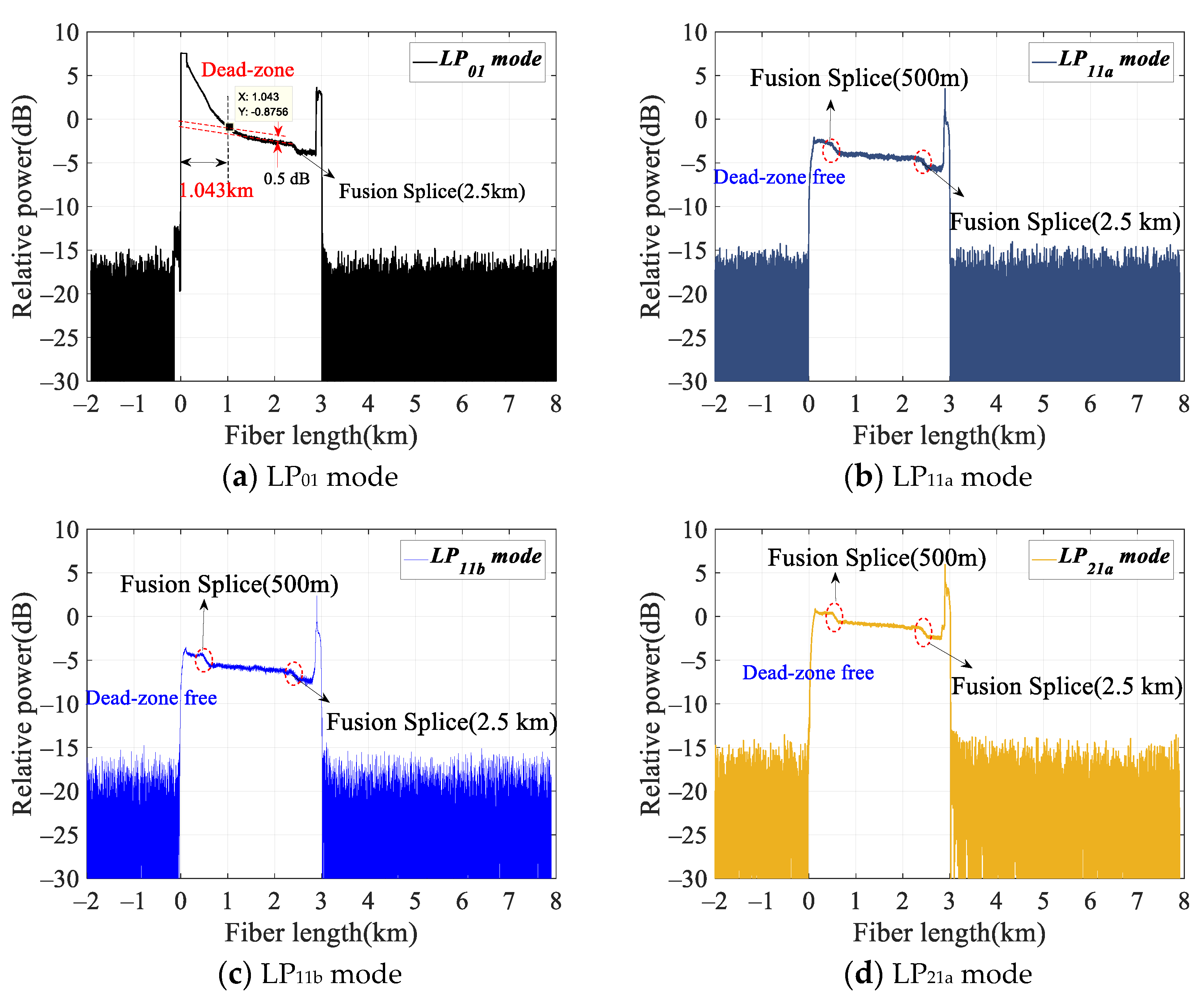
01 mode is affected by a dead zone at the beginning of the FMF link, as shown in
Figure 5a. Because the attenuation blind area caused by Fresnel reflection in the front segment is about 1043 m, the fusion splice fault at 500 m cannot be effectively detected and located. Since the blind area has no impact on the fusion splice fault at 2.5 km, effective detection and location can be achieved. This experimental setup is similar to the traditional single-mode OTDR shown in
Figure 2, so the dead zone problem still exists.
Next, the optical pulses are injected through the LP
01 port of the photonic lantern, and the backscattering curves of the higher-order spatial mode are obtained from the LP
11a, LP
11b, LP
21a, LP
21b, and LP
02 ports of the photonic lantern.
Figure 5b shows the Rayleigh backscattering curve of the LP
11a spatial mode. Obviously, the blind zone disappears, and the precise detection and location of the fusion splice fault at 500 m and 2.5 km can be realized. The main reason is that the Fresnel reflection from the optical fiber end face, the circulator interior, and the connector only occurs on the fundamental mode LP
01 of the injected optical pulse. The Rayleigh backscattering power along the entire FMF link will not saturate PD. Similarly, the LP
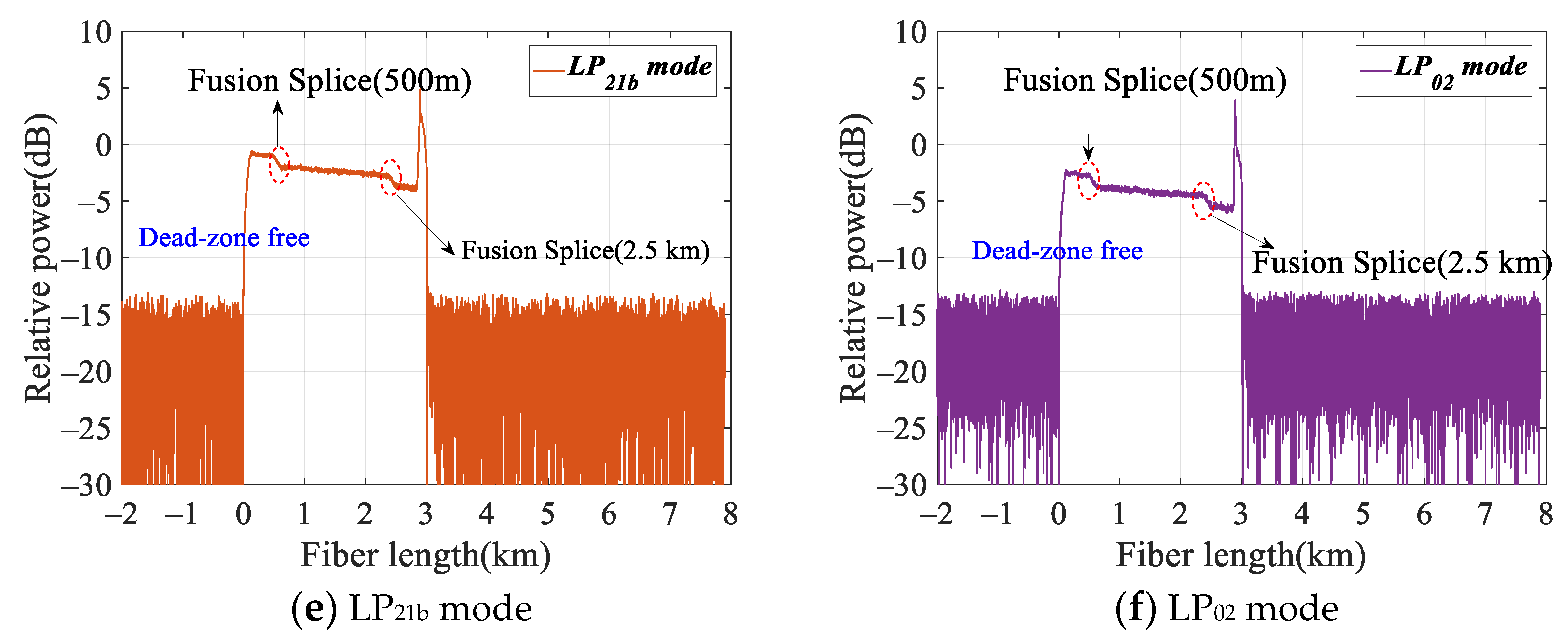
11b, LP
21a, and LP
21b modes can effectively eliminate the dead zone, as shown in
Figure 5c–f, and achieve accurate detection and positioning of the fusion splice fault locations at 500 m and 2.5 km. At the same time, it can be seen that the higher-order spatial mode has higher fault detection sensitivity for fusion splice faults, and the higher-order spatial mode fusion splice loss is greater. The previous work has also confirmed this conclusion [
23], which can realize the high-sensitivity fault detection of FMF links. Therefore, through the analysis of the above results, we can conclude that the proposed method based on the higher-order spatial mode can effectively eliminate the blind area caused by the Fresnel reflection of the front end of the fiber end and realize the accurate detection of the dead zone for the FMF link.
In order to further verify that the scheme can achieve higher precision dead-zone-free detection, we conducted an in-depth analysis of the detection results of the fusion splice located 100 m under the condition of a 100 ns probe optical pulse, as shown in
Figure 6. The Rayleigh backscattering curve of LP
01 mode is affected by a dead zone at the beginning of the FMF link, and the length of the blind zone is about 174 m, so the fusion splice fault at 100 m cannot be effectively detected, as shown in
Figure 6a. The higher-order spatial mode Rayleigh backscattering can realize the precise detection of the fusion splice fault at 100 m, as shown in
Figure 6b. It can be concluded that this scheme can realize higher precision detection without a dead zone.
Similarly, any spatial mode can be used to inject the detection optical pulse, while other spatial modes can be used to achieve dead-zone-free detection. Using LP
11a, LP
11b, LP
21a, LP
21b, and LP
02 modes as excitation spatial modes, respectively, the Rayleigh backscattering curves of other spatial modes of FMF are obtained from other ports of the photonic lantern. The measurement results are shown in
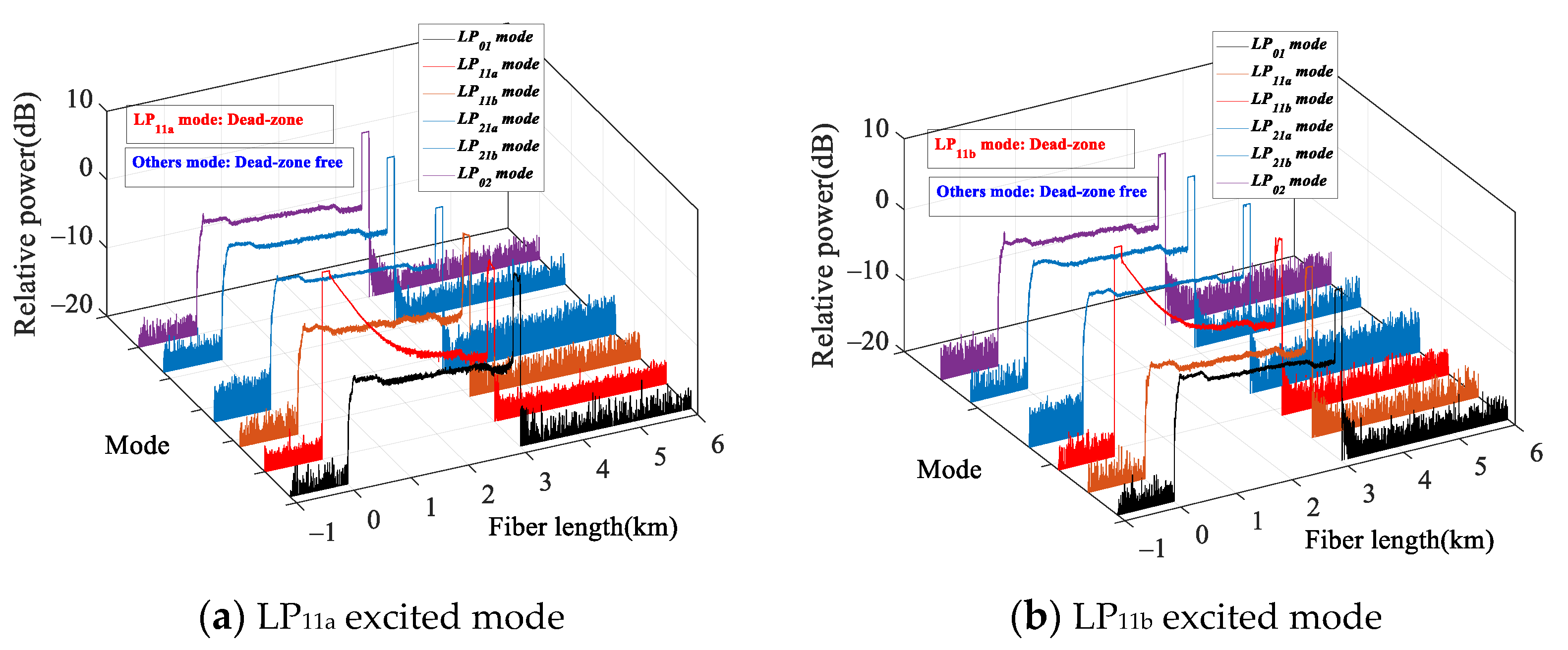
Figure 7. According to the analysis of
Figure 7a–d, when LP
11a, LP
11b, LP
21a, LP
21b, and LP
02 modes are excitation modes, respectively, the Fresnel reflections from the end face of the fiber, the interior of the circulator, and the connector only occur in the corresponding excitation spatial mode of the injected optical pulse. The attenuation blind area caused by front Fresnel reflection in the excitation mode is approximately 1000 m, which makes the fusion splice fault at 500 m unable to be effectively detected and located. Since the dead zone has no impact on the fusion splice fault at 2.5 km, effective detection and location can be achieved. The Rayleigh backscattering, which reflects the fault distribution characteristics of the FMF link, can be detected by the non-excited higher-order spatial mode to realize the dead-zone-free accurate detection of fusion splice faults at 500 m. Through the above analysis, it can be seen that the scheme can effectively eliminate the dead zone caused by the front Fresnel reflection and realize the non-excitation mode without blind area detection. However, the dead zone is also caused by the reflection events (such as the FC/APC and FC/PC connector mismatch) inside the FMF link. Therefore, how to realize dead-zone-free detection inside the FMF link is a worthwhile and important area of research.

