Article

Modulation of Second-Order Sideband Efficiency in an Atom-Assisted Optomechanical System

1
School of Physics and Optoelectronic Engineering, Yangtze University, Jingzhou 434023, China
2
Engineering Research Center of Vehicle Display Integrated Systems in Anhui Province, School of Electrical Engineering, Anhui Polytechnic University, Wuhu 241000, China
*
Authors to whom correspondence should be addressed.
Photonics 2024, 11(5), 416; https://doi.org/10.3390/photonics11050416
Submission received: 31 March 2024 / Revised: 19 April 2024 / Accepted: 26 April 2024 / Published: 30 April 2024
(This article belongs to the Special Issue Optics and Laser: Light Field Manipulation)

Abstract

:
We propose an efficient scheme to enhance the generation of optical second-order sidebands (OSSs) in an atom-assisted optomechanical system. The cavity field is coupled with a strong driving field and a weak probe field, and a control field is applied to the atom. We use the steady-state method to analyze the nonlinear interaction in the system, which is different from the traditional linear analysis method. The existence of an auxiliary three-level atom driven by the control field significantly enhances the generation of an OSS. It is found that the efficiency of the OSS can be effectively modulated by adjusting the Rabi frequency of the control field, optomechanical cooperativity and atomic coupling strength. Our scheme provides a promising solution for controlling light propagation and has potential application in quantum optical devices and quantum information networks.

1. Introduction

In recent decades, the study of cavity optomechanical systems has developed rapidly in theory and experiments, such as radiation-pressure fluctuations, three-dimensional viscous confinement and cooling, tunable electromagnetically induced multi-transparencies, quantum-coherent coupling, etc. [1,2,3,4,5,6,7,8]. As we know, a cavity optomechanical system comprises an optical nano/microcavity coupled with a mechanical oscillator via radiation pressure coupling. Due to the continuous advancements in micro- and nano-processing technology, the fabrication of high-quality optical microcavities has been significantly improved [9,10]. This progress has led to the rapid development of cavity optomechanical systems in various applied fields, such as normal mode splitting [11,12], mechanical resonator sideband cooling [13,14], quantum sensors [15,16,17,18], quantum information processes [19,20,21], etc. An intriguing phenomenon observed in a cavity optomechanical system is known as optomechanically induced transparency (OMIT) [22,23,24]. This effect serves as an analog to electromagnetically induced transparency and can be comprehensively understood as the linearization of optomechanical interactions [25,26,27]. Due to the correlation between the output spectrum and the measured physical quantities, the transmission window of the probe field can be applied to the measurement of small physical quantities in optically and mechanically induced transparent structures.
In recent years, there has been a growing interest in nonlinear optical–mechanical effects within cavity optomechanical systems. By considering the nonlinear interaction term in the dynamic equation of an optical–mechanical system, many interesting phenomena caused by nonlinear optical–mechanical interactions have been revealed, and the scope of cavity optical–mechanical systems has been expanded to topics such as the generation of second-order sidebands [28,29,30], sideband frequency combs [31], optical–mechanical chaos [32], photon-blockade effects [33,34] and carrier–envelope phase correlation effects [35,36]. Among these phenomena, OSS is the first non-linear sideband of the higher-order sidebands, and the generation of high-order sidebands stands out as a characteristic manifestation of nonlinear interactions. It has garnered significant attention in various fields, such as optical frequency combs [29,30], optical communication [36,37] and high-sensitivity measurement [38]. However, the generally weak effect of high-order sidebands has limited their practical applications. As a consequence, a significant amount of research effort has been dedicated to enhancing the higher-order sideband effects in optomechanical systems, leading to the development of numerous hybrid optomechanical systems. For example, the hybrid atomic cavity optomechanical system [39,40,41,42], the hybrid electromagnetic optomechanical system [43] and the PT symmetric optical resonator [44] have been used to enhance the high-order sideband effect.
In this paper, we introduce a novel hybrid optomechanical system aimed at enhancing the effects of a second-order sideband. This system comprises an optical microcavity with a movable mirror and a three-level cold atom. In this work, we found that the Rabi frequency of the atom, optomechanical cooperativity and atomic coupling strength play important roles in the generation of second-order sideband conversion efficiency. Moreover, we also found that the conversion efficiency of the second-order sideband can be significantly enhanced under different parameters in the hybrid optical–mechanical system of a three-level cold atom.
The structure of this paper is organized as follows. Section 2 presents the model and Hamiltonian of the system and derives the analytical expression of the output field. Section 3 discusses the influence of system parameters on the generation of the second-order sideband, and analyses the mutual compensation between the influence of the parameters. Section 4 presents the conclusions of this paper.

2. Theoretical Model and Equations

The model we consider is shown schematically in Figure 1. The system consists of an optical microcavity with a mobile reflector and a three-level atom. The resonance frequency and loss rate of the cavity are described as ω c a v and κ a . The cavity is driven by a strong driving field with a frequency of ω d and an amplitude of ε d as well as a weak probe field with a frequency of ω p and an amplitude of ε p , respectively. The three-level atom is located in the cavity, and its excited and ground states are labeled as | 1 and | 2 , | 3 . The atomic transition | 1 | 2 with an energy-level difference of ω 12 = ω 1 ω 2 is coupled by the cavity mode of frequency ω c a v . The corresponding frequency detuning and coupling strength are indicated by Δ c a v = ω 12 ω c a v and g . The transition | 1 | 3 is driven by a control field of frequency ω 0 with Rabi frequency Ω and detuning Δ 0 = ω 12 ω 0 . The interaction between the cavity mode and the mechanical resonator is described by radiation pressure with a coupling strength of G , where the frequency of the mechanical resonator is ω m .
Using the rotating wave approximation of the system, the full Hamiltonian of the system, as shown in Figure 1, can be written as [26,27,32,34]
H I = Δ c a v σ 11 + ( Δ c a v Δ d ) σ 22 + ( Δ c a v Δ 0 ) σ 33 + ( Δ d Δ c a v ) a a + ω m b b G a a ( b + b ) + ( Ω σ 13 + g a σ 12 + H . c . ) + i 2 η γ a [ ( ε d a ε d * a ) + ( ε p a e i ( Δ p Δ d ) t ε p * a e i ( Δ p Δ d ) t ) ] ,
where a and b ( a and b ) are the annihilation (creation) operators of the cavity field and phonon field, respectively; Δ p = ω p ω c a v is the detuning of the cavity resonance frequency and the frequency of the probe laser; and Δ d = ω d ω c a v is the detuning of the cavity resonance frequency and the frequency of the drive laser.
The term Δ c a v σ 11 + ( Δ c a v Δ d ) σ 22 + ( Δ c a v Δ 0 ) σ 33 + ( Δ d Δ c a v ) a a + ω m b b in Equation (1) describes the free Hamiltonian of the system. The term G a a ( b + b ) describes the coupling between the cavity field and the phonon field with the coupling coefficient G . The term Ω σ 13 describes the coupling between the control field and the atom. The term g a σ 12 describes the coupling between the cavity field and the atom with the coupling coefficient g . The term i 2 η γ a ( ε d a ε d * a ) describes the interaction between the cavity field and the drive field, and i 2 η γ a ( ε p a e i ( Δ p Δ d ) t ε p * a e i ( Δ p Δ d ) t ) describes the interaction between the cavity field and the probe field. The amplitude of the driving field [7] is defined as ε d = P d / ω d , where P d is the power of the driving field, and the amplitude of the probe field is defined as ε p = P p / ω p , where P p is the power of the probe field. In addition, the coupling coefficient η c is assumed to be a constant, and the specific value η c = 1 / 2 .
Based on the Hamiltonian in Equation (1) and considering the damping of the cavity field and phonon field, the quantum dynamic evolution of the system can be described by the following Heisenberg–Langevin equation [33,35]:
a ˙ = [ κ a + i ( Δ d Δ c a v ) i G ( b + b ) ] a i g * σ 21               + 2 η γ a ε d + 2 η γ a ε p e i ( Δ p Δ d ) t + f a , b ˙ = ( γ m + i ω m ) b i G a a + f b , σ ˙ 21 = ( γ 12 + i Δ d ) σ 21 + i g a ( σ 11 σ 22 ) i Ω σ 23 + f 21 , σ ˙ 23 = [ γ 32 + i ( Δ d Δ 0 ) ] σ 23 i Ω * σ 21 + f 23 ,
where the quantum noise of the cavity terms f a , f b , f 21 and f 23 , have been neglected in Equation (2), because f a = f b = f 21 = f 23 = 0 . κ a and γ m are the loss rates of the cavity and atom. It should be noted that the steady-state solution of the system is not easy to obtain because of the nonlinear terms (i.e., i G a ( b + b ) and i G a a ) in Equation (2). Using the linearization of the Heisenberg–Langevin equations, these nonlinear terms are neglected in many previous works. However, we focus on the efficient generation of a second-order sideband caused by the nonlinear terms in this hybrid system.
Based on the assumption that the driving field is much stronger than the probe field, the perturbation method is used to solve Equation (2). This method allows us to describe all operators in the form of o = o s + δ o ( o = a , a , b , b ) , where o s is the steady-state solution. We can write operators as their expected values, because we only focus on the value response of the probe field in the system. Then, the expression of the steady-state solution can be obtained as follows:
a s = 2 η κ a ε d γ a + i Δ + g 2 γ 12 + i Δ d Ω 2 γ 32 + i ( Δ d Δ 0 ) , b s = i G a ¯ 2 γ m + i ω m .
Then, we focus on the perturbation made by the probe field. The evolution of the perturbation can be written as
δ a ˙ = ( κ a + i Δ ) δ a i g * δ c + 2 η γ a ε p e i ( Δ p Δ d ) t , δ b ˙ = ( γ m + i ω m ) δ b i G δ a δ a , δ c ˙ = ( γ 12 + i Δ d ) δ c i g δ a i Ω δ d , δ d ˙ = [ γ 32 + i ( Δ d Δ 0 ) ] δ d i Ω * δ c .
In this work, we focus on the influence of the probe field caused by the nonlinear terms (i.e., i G δ a ( δ b + δ b ) and i G δ a δ a ). Therefore, we give the trial solution of Equation (4), which has the following form:
δ a = A 1 e i δ t + A 1 + e i δ t + A 2 e 2 i δ t + A 2 + e 2 i δ t , δ a = ( A 1 ) * e i δ t + ( A 1 + ) * e i δ t + ( A 2 ) * e 2 i δ t + ( A 2 + ) * e 2 i δ t , δ b = B 1 e i δ t + B 1 + e i δ t + B 2 e 2 i δ t + B 2 + e 2 i δ t , δ b = ( B 1 ) * e i δ t + ( B 1 + ) * e i δ t + ( B 2 ) * e 2 i δ t + ( B 2 + ) * e 2 i δ t ,
where the coefficients A 1 and A 2 correspond to the first-order sideband with frequency ω d ± δ and second-order sideband with frequency ω d ± 2 δ , and the signs + and in ω d ± δ and ω d ± 2 δ describe the lower and upper sidebands, respectively. When the probe field and pump field drive the cavity optomechanical system simultaneously, due to the nonlinear terms (i.e., i G δ a ( δ b + δ b ) , i G δ a δ a ) in Equation(4), there are a series of frequencies ω d ± n δ ( n is an integer) in the output field, where the first upper and lower sidebands are also called the anti-Stokes field and Stokes field. The output fields with frequencies of ω d + 2 δ and ω d 2 δ are divided into higher and lower second-order sidebands. By substituting Equation (5) into Equation (4) and comparing the coefficients of the same order, we can obtain the amplitude of the first-order sideband and second-order sideband:
A 1 = F 3 ( δ ) F 4 ( δ ) 2 η c κ a ε p F 12 ( δ ) F 13 ( δ ) , ( A 1 + ) * = [ F 3 ( δ ) F 4 ( δ ) ] G 2 | a s | 2 A 1 F 11 ( δ ) , B 1 = i G [ a s ( A 1 + ) * + a s * A 1 ] F 4 ( δ ) , ( B 1 + ) * = i G [ a s ( A 1 + ) * + a s * A 1 ] F 3 ( δ ) , A 2 = [ F 13 ( 2 δ ) + [ F 3 ( 2 δ ) F 4 ( 2 δ ) ] G 2 a s ] A 1 ( A 1 + ) * F 12 ( 2 δ ) F 13 ( 2 δ ) + i G F 3 ( δ ) F 4 ( δ ) F 11 ( 2 δ ) A 1 ( B 1 + ) * i G 3 | a s | 2 F 3 ( δ ) F 4 ( δ ) [ F 3 ( 2 δ ) F 4 ( 2 δ ) ] ( A 1 + ) * B 1 [ F 12 ( 2 δ ) F 13 ( 2 δ ) ] F 11 ( 2 δ ) ,
with
F 1 ( n δ ) = i n δ + ( κ a i Δ ) , F 2 ( n δ ) = i n δ + ( κ a + i Δ ) , F 3 ( n δ ) = i n δ + ( γ m i ω m ) , F 4 ( n δ ) = i n δ + ( γ m + i ω m ) , F 5 ( n δ ) = i n δ + ( γ 12 i Δ d ) , F 6 ( n δ ) = i n δ + ( γ 12 + i Δ d ) , F 7 ( n δ ) = i n δ + γ 32 i ( Δ d Δ 0 ) , F 8 ( n δ ) = i n δ + γ 32 + i ( Δ d Δ 0 ) , F 9 ( n δ ) = | g | 2 F 7 ( n δ ) / ( | Ω | 2 + F 5 ( n δ ) F 7 ( n δ ) ) , F 10 ( n δ ) = | g | 2 F 8 ( n δ ) / ( | Ω | 2 + F 6 ( n δ ) F 8 ( n δ ) ) , F 11 ( n δ ) = [ F 1 ( n δ ) + F 9 ( n δ ) ] F 3 ( n δ ) F 4 ( n δ ) + [ F 3 ( n δ ) F 4 ( n δ ) ] G 2 | a s | 2 , F 12 ( n δ ) = [ F 2 ( n δ ) + F 10 ( n δ ) ] F 3 ( n δ ) F 4 ( n δ ) + [ F 4 ( n δ ) F 3 ( n δ ) ] G 2 | a s | 2 , F 13 ( n δ ) = [ F 3 ( n δ ) F 4 ( n δ ) ] [ F 4 ( n δ ) F 3 ( n δ ) ] G 4 | a s | 4 F 11 ( n δ ) .
From Equation (6), it can be seen that the amplitude of the first-order sideband is proportional to the probe field, while the amplitude of the second-order sideband contains a term from the upconverted first-order sideband generation process and a term directly describing the second-order sideband generation process. According to the input–output relation of the cavity s o u t = s i n η c κ a a [7], we can obtain the output transmission spectrum as follows:
s o u t = c 1 e i ω d t + c p e i ω p t η c κ a A 2 e i ( 2 ω p ω d ) t η c κ a A 1 + e i ( 2 ω d ω p ) t η c κ a A 2 + e i ( 3 ω d 2 ω p ) t ,
where the terms c 1 = ε d η c κ a a s and c p = ε p η c κ a A 1 represent the frequency of ω d and ω p in the output transmission spectrum, respectively; the term η c κ a A 1 + e i ( 2 ω d ω p ) t represents the Stokes process; the term η c κ a A 2 e i ( 2 ω p ω d ) t describes the second-order upper sideband process, in which the output field with frequency ω d + 2 Ω can be produced; and the term η c κ a A 2 + e i ( 3 ω d 2 ω p ) t describes the second-order lower sideband process, in which the output field with frequency ω d 2 Ω can be produced.
The transmission of the probe field is defined as t p = c p / ε p . As mentioned above, the optical transmission strength can be obtained as follows
| t p | 2 = | 1 η c κ a A 1 ε p | 2 .
In this work, we introduce a dimensionless parameter to describe the conversion efficiency of the second-order sideband in this hybrid system.
η = | η c κ a A 2 / ε p | .
The above equation can describe the generation efficiency of the second-order sideband. In the next section, we will discuss how to achieve the enhancement of the second-order sideband.

3. Numerical Results and Discussion

In this section, we will numerically investigate the properties of second-order sideband generation in Figure 2, Figure 3, Figure 4 and Figure 5. In this study, our primary focus lies in the generation efficiency of the second-order sideband.
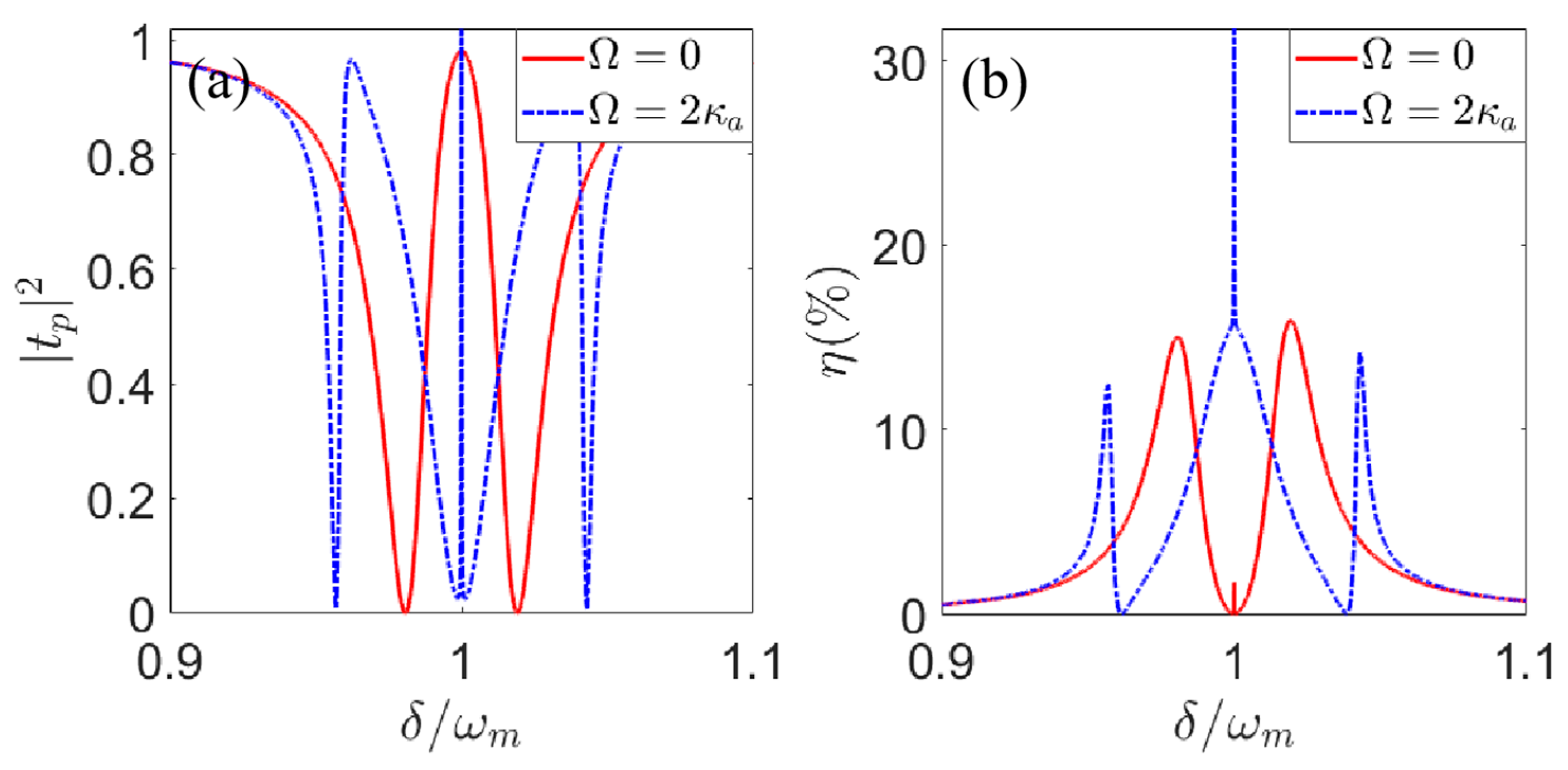
First, we examine the influence of the atom on the efficiency of second-order sideband generation. In Figure 2, we plot the transmission | t p | 2 and the efficiency of the second-order upper sideband η as a function of detuning δ / ω m for different values of the Rabi frequency Ω of the control field. The red solid line and blue dash-dotted line in Figure 2 correspond to the cases of Ω = 0 and Ω = 2 κ a , respectively. In the absence of the control field, i.e., Ω = 0 , there is a transparent window near the resonance condition δ = ω m . At the positions of the transmission dip, the conversion efficiency of the second-order sideband η only arrives at 15.5 % (see Figure 2b, blue dash-dotted line). When the Rabi frequency of the control field exists and increases to Ω = 2 κ a , Rabi splitting occurs, the number of peaks of the second-order sideband changes from two to three and the conversion efficiency of the second-order sideband η is significantly improved, reaching 31.5 % . One can conclude that the existence of an intracavity atom driven by a control field can significantly improve the conversion efficiency of the second-order sideband.
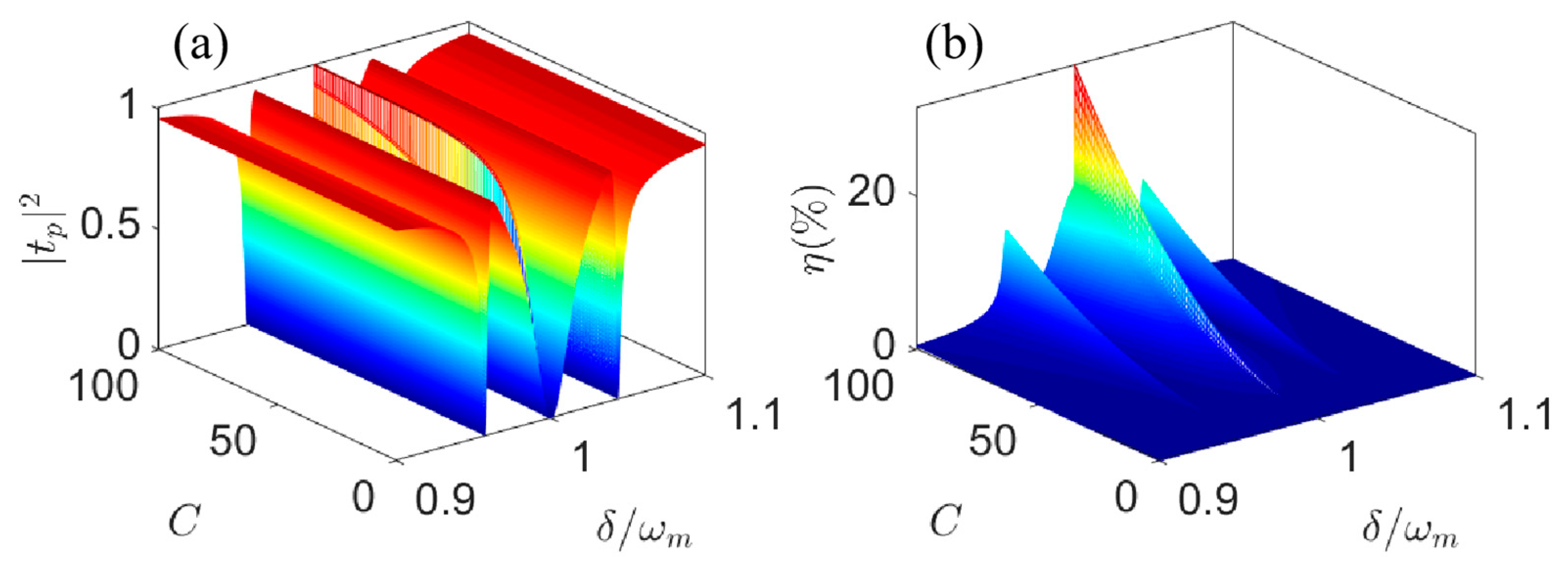
Second, we investigate the effect of optomechanical cooperativity C on the efficiency of the second-order sideband. Figure 3 plots | t p | 2 and η as a function of detuning δ / ω m for different levels of optomechanical cooperativity C . Here, we give the optomechanical cooperativity C = G 2 a ¯ 2 / κ a γ m [42]. As we know, optomechanical cooperativity C is negatively correlated with cavity field attenuation κ a and mechanical mode attenuation γ m . From the spectrum lines of Figure 3, we can find that the conversion efficiency of the second-order sideband increases significantly with an increase in optomechanical cooperativity from 0 to 100. Therefore, enhanced optomechanical cooperativity C can improve the efficiency of the second-order sideband. According to Equation (4), the conversion efficiency of the second-order sideband mainly comes from the nonlinear terms (i.e., i G δ a ( δ b + δ b ) , i G δ a δ a ). That is to say, the efficiency of the second-order sideband is related to optomechanical coupling strength G . In our model, the optomechanical cooperativity C will increase proportionally with an increase in optomechanical coupling strength G . Thus, the conversion efficiency of the second-order sideband increases with an increase in optomechanical cooperativity C .
Third, we explore the influence of atom–cavity coupling strength on the efficiency of the second-order sideband. We plot the transmission | t p | 2 and the efficiency of the second-order upper sideband η as a function of detuning δ / ω m for different values of coupling strength g in Figure 4. From the three spectrum lines of Figure 4 with different values of coupling strength g = 0.5 κ a (see Figure 4, red solid line), g = κ a (see Figure 4, blue dash-dotted line) and g = 1.5 κ a (see Figure 4, yellow dashed line), when adjusting the atomic coupling strength g , we can find that the second-order sidebands rapidly decrease as the coupling strength g increases. This indicates that atom–cavity coupling inhibits the generation of a second-order sideband. Therefore, controlling the atom–cavity coupling strength is also an effective means to modulate the generation of a second-order sideband.
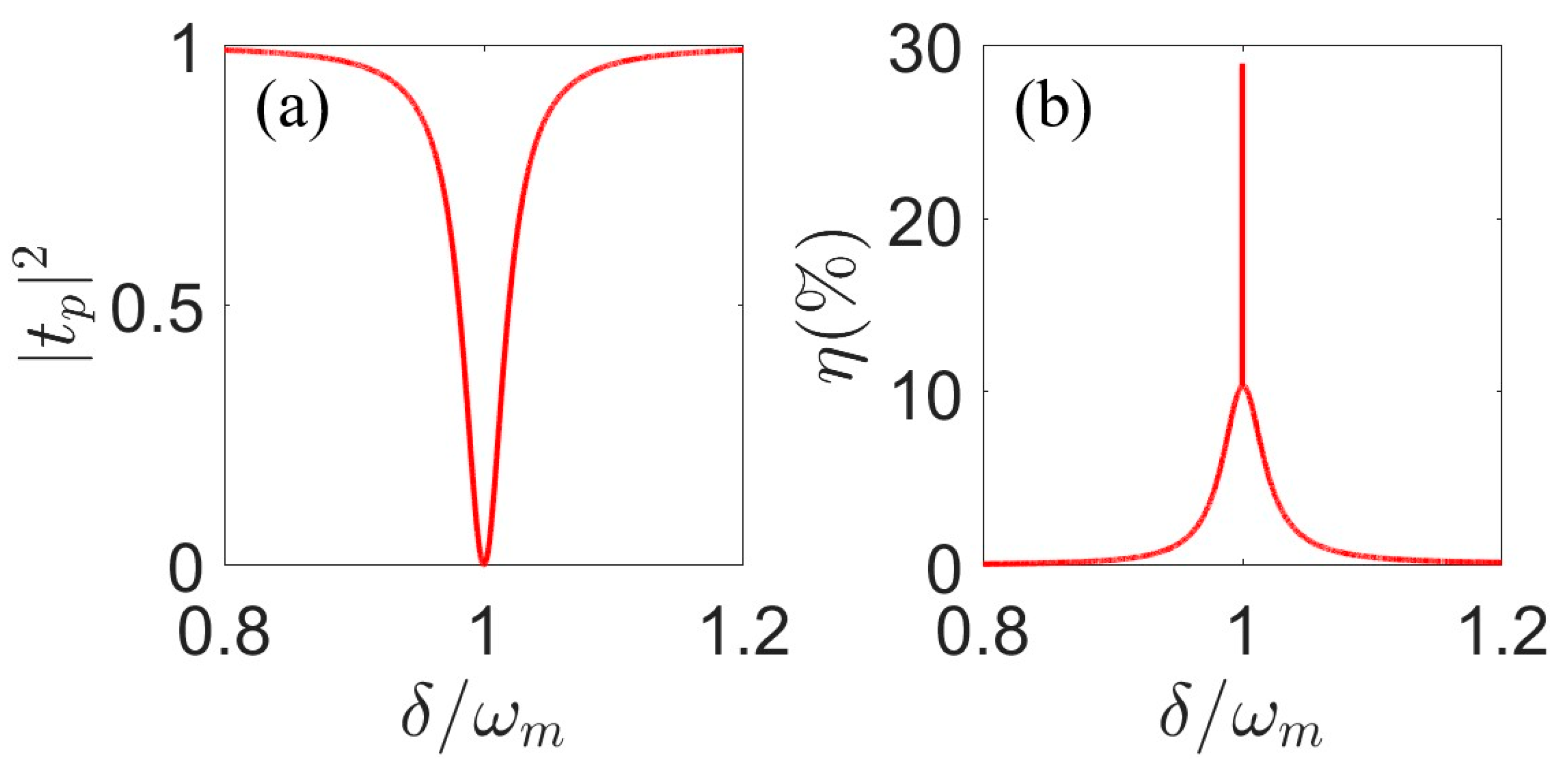
Finally, according to Equation (4), the second-order sideband efficiency η is directly influenced by optomechanical coupling. When the optomechanical coupling is very weak, we can reduce the strength of the atom–cavity coupling to compensate for the nonlinear effect. In Figure 5, by setting optomechanical cooperativity to C = 0.01 and the atom–cavity coupling strength to g = 0.00015 κ a , we can find that the conversion efficiency of the second-order sideband can also reach nearly 30 % . This demonstrates that the optomechanical cooperativity C and the atom-cavity coupling strength g can effectively control the second-order sideband conversion efficiency of the system.

4. Conclusions

In summary, our study focused on the theoretical investigation of the enhanced generation of an optical second-order sideband in a three-level cold atom-assisted optomechanical system. The optomechanical cavity with the three-level cold atom is driven by a strong control field and a weak probe pulse. By utilizing the perturbation method, we successfully derived explicit analytical expressions for the transmission intensity and the conversion efficiency of the second-order sideband. Based on these equations and by carefully selecting appropriate parameters, we analyze the influences of Rabi frequency of the atom Ω , optomechanical cooperativity C and atomic coupling strength g on the conversion efficiency of the second-order sideband. The results show that the second-order sideband conversion efficiency can be enhanced by adjusting the Rabi frequency of the atom Ω , optomechanical cooperativity C and atomic coupling strength g , and the effects of different parameters on the second-order sideband conversion efficiency can compensate for each other. The present investigation offers a promising pathway for modulating the nonlinear optical properties of hybrid optomechanical systems.

Author Contributions

Conceptualization, W.-X.Y. and L.L.; data curation, L.L. and L.-X.F.; formal analysis, L.L., T.S. and L.-X.F.; methodology, L.L.; resources, T.S.; software, L.L. and L.-X.F.; writing—original draft preparation, L.L., T.S. and L.-X.F.; writing—review and editing, L.L. and L.-X.F. All authors have read and agreed to the published version of the manuscript.

Funding

This research was supported by the National Natural Science Foundation of China (Grant Nos. 12075036, 12104067 and 12375008), the Innovation Research Groups of the Hubei Natural Science Foundation of China (2023AFA025) and the Science and Technology Research Project of the Education Department of Hubei Province (Q20211314).

Institutional Review Board Statement

Not applicable.

Informed Consent Statement

Not applicable.

Data Availability Statement

Data are contained within the article.

Conflicts of Interest

The authors declare no conflicts of interest.

References

  1. Caves, C.M. Quantum-mechanical radiation-pressure fluctuations in an interferometer. Phys. Rev. Lett. 1980, 45, 75. [Google Scholar] [CrossRef]
  2. Chu, S.; Hollberg, L.; Bjorkholm, J.E.; Cable, A.; Ashkin, A. Three-dimensional viscous confinement and cooling of atoms by resonance radiation pressure. Phys. Rev. Lett. 1985, 55, 48. [Google Scholar] [CrossRef] [PubMed]
  3. Huang, S.; Agarwal, G.S. Normal mode splitting and antibunching in stokes and anti-stokes processes in cavity optomechanics: Radiation pressure induced four-wave mixing cavity optomechanics. Phys. Rev. A 2010, 81, 76. [Google Scholar] [CrossRef]
  4. Huang, S.; Agarwal, G.S. Electromagnetically induced transparency with quantized fields in optocavity mechanics. Phys. Rev. A 2011, 83, 43826. [Google Scholar] [CrossRef]
  5. Wu, Z.; Luo, R.H.; Zhang, J.Q.; Wang, Y.H.; Yang, W.; Feng, M. Force-induced transparency and conversion between slow and fast light in optomechanics. Phys. Rev. A 2017, 96, 033832. [Google Scholar] [CrossRef]
  6. Liu, Q.C.; Li, T.F.; Luo, X.Q.; Zhao, H.; Xiong, W.; Zhang, Y.S.; Chen, Z.; Liu, J.S.; Chen, W.; Nori, F.; et al. Method for identifying electromagnetically induced transparency in a tunable circuit quantum electrodynamics system. Phys. Rev. A 2016, 93, 053838. [Google Scholar] [CrossRef]
  7. Weis, S.; Riviere, R.; Deleglise, S.; Gavartin, E.; Arcizet, O.; Schliesser, A.; Kippenberg, T.J. Optomechanically induced transparency. Science 2010, 330, 1520–1523. [Google Scholar] [CrossRef]
  8. Verhagen, E.; Deléglise, S.; Weis, S.; Schliesser, A.; Kippenberg, T.J. Quantum-coherent coupling of a mechanical oscillator to an optical cavity mode. Nature 2012, 482, 63–67. [Google Scholar] [CrossRef] [PubMed]
  9. Safavi-Naeini, A.H.; Alegre, T.M.; Chan, J.; Eichenfield, M.; Winger, M.; Lin, Q.; Hill, J.T.; Chang, D.E.; Painter, O. Electromagneticauy induced transparency and slow light with optomechanics. Nature 2011, 472, 69–73. [Google Scholar] [CrossRef]
  10. Karuza, M.; Biancofiore, C.; Bawaj, M.; Molinelli, C.; Galassi, M.; Natali, R.; Tombesi, P.; Di Giuseppe, G.; Vitali, D. Optomechanically induced transparency in a membrane-in-the-middle setup at room temperature. Phys. Rev. A At. Mol. Opt. Phys. 2013, 88, 013804. [Google Scholar] [CrossRef]
  11. Dobrindt, J.M.; Wilson-Rae, I.; Kippenberg, T.J. Parametric normal-mode splitting in cavity optomechanics. Phys. Rev. Lett. 2008, 101, 263602. [Google Scholar] [CrossRef] [PubMed]
  12. Gröblacher, S.; Hammerer, K.; Vanner, M.R.; Aspelmeyer, M. Observation of strong coupling between a micromechanical resonator and an optical cavity field. Nature 2009, 60, 724–727. [Google Scholar] [CrossRef] [PubMed]
  13. Nie, W.; Chen, A.; Lan, Y. Coupling mechanical motion of a single atom to a micromechanical cantilever. Opt. Express 2017, 25, 32931–32947. [Google Scholar] [CrossRef]
  14. Arcizet, O.; Cohadon, P.F.; Briant, T.; Pinard, M.; Heidmann, A. Radiation-pressure cooling and optomechanical instability of a micromirror. Nature 2006, 444, 71–74. [Google Scholar] [CrossRef] [PubMed]
  15. Bao, L.; Qi, B.; Dong, D.; Nori, F. Fundamental limits for reciprocal and nonreciprocal non-Hermitian quantum sensing. Phys. Rev. A 2021, 103, 042418. [Google Scholar] [CrossRef]
  16. Li, L.; Yang, W.X.; Zhang, Y.; Shui, T.; Chen, A.X.; Jiang, Z. Enhanced generation of charge-dependent second-order sideband and high-sensitivity charge sensors in a gain-cavity-assisted optomechanical system. Phys. Rev. A 2018, 98, 063840. [Google Scholar] [CrossRef]
  17. Jing, H.; Lü, H.; Özdemir, S.K.; Carmon, T.; Nori, F. Nanoparticle sensing with a spinning resonator. Optica 2018, 5, 1424–1430. [Google Scholar] [CrossRef]
  18. Liu, S.; Liu, B.; Wang, J.; Sun, T.; Yang, W.X. Realization of a highly sensitive mass sensor in a quadratically coupled optomechanical system. Phys. Rev. A 2019, 99, 033822. [Google Scholar] [CrossRef]
  19. Singh, S.K.; Peng, J.X.; Asjad, M.; Mazaheri, M. Entanglement and coherence in a hybrid Laguerre–Gaussian rotating cavity optomechanical system with two-level atoms. J. Phys. B At. Mol. Opt. Phys. 2021, 54, 215502. [Google Scholar] [CrossRef]
  20. Lü, X.Y.; Zhang, W.M.; Ashhab, S.; Wu, Y.; Nori, F. Quantum-criticality-induced strong Kerr nonlinearities in optomechanical systems. Sci. Rep. 2013, 3, 2943. [Google Scholar] [CrossRef]
  21. Lodahl, P.; Mahmoodian, S.; Stobbe, S.; Rauschenbeutel, A.; Schneeweiss, P.; Volz, J.; Pichler, H.; Zoller, P. Chiral quantum optics. Nature 2017, 541, 473–480. [Google Scholar] [CrossRef] [PubMed]
  22. Agarwal, G.S.; Huang, S. Electromagnetically induced transparency in mechanical effects of light. Phys. Rev. A 2010, 1, 041803. [Google Scholar] [CrossRef]
  23. Aspelmeyer, M.; Kippenberg, T.J.; Marquardt, F. Cavity optomechanics. Rev. Mod. Phys. 2014, 86, 1391. [Google Scholar] [CrossRef]
  24. Jiang, C.; Liu, H.; Cui, Y.; Li, X.; Chen, G.; Chen, B. Electromagnetically induced transparency and slow light in two-mode optomechanics. Opt. Express 2013, 1, 12165–12173. [Google Scholar] [CrossRef] [PubMed]
  25. Hou, B.P.; Wei, L.F.; Wang, S.J. Optomechanically induced transparency and absorption in hybridized optomechanical systems. Phys. Rev. A 2015, 92, 033829. [Google Scholar] [CrossRef]
  26. Bai, C.; Hou, B.P.; Lai, D.G.; Wu, D. Tunable optomechanically induced transparency in double quadratically coupled optomechanical cavities within a common reservoir. Phys. Rev. A 2016, 93, 043804. [Google Scholar] [CrossRef]
  27. Suzuki, H.; Brown, E.; Sterling, R. Nonlinear dynamics of an optomechanical system with a coherent mechanical pump: Second-order sideband generation. Phys. Rev. A 2015, 92, 33823. [Google Scholar] [CrossRef]
  28. Xiong, H.; Si, L.G.; Zheng, A.S.; Yang, X.; Wu, Y. Higher-order sidebands in optomechanically induced transparency. Phys. Rev. A 2012, 86, 013815. [Google Scholar] [CrossRef]
  29. Liu, S.; Yang, W.X.; Zhu, Z.; Shui, T.; Li, L. Quadrature squeezing of a higher-order sideband spectrum in cavity optomechanics. Opt. Lett. 2018, 43, 9. [Google Scholar] [CrossRef]
  30. Li, J.; Li, J.; Xiao, Q.; Wu, Y. Giant enhancement of optical high-order sideband generation and their control in a dimer of two cavities with gain and loss. Phys. Rev. A 2016, 93, 063814. [Google Scholar] [CrossRef]
  31. Li, J.; Qu, Y.; Yu, R.; Wu, Y. Generation and control of optical frequency combs using cavity electromagnetically induced transparency. Phys. Rev. A 2018, 97, 023826. [Google Scholar] [CrossRef]
  32. Lü, X.Y.; Jing, H.; Ma, J.Y.; Wu, Y. PT-symmetry-breaking chaos in optomechanics. Phys. Rev. Lett. 2015, 114, 253601. [Google Scholar] [CrossRef] [PubMed]
  33. Wu, Y.; Yang, X. Strong-coupling theory of periodically driven two-level systems. Phys. Rev. Lett. 2007, 98, 013601. [Google Scholar] [CrossRef]
  34. Gao, Y.P.; Liu, X.F.; Wang, T.J.; Cao, C.; Wang, C. Photon excitation and photon-blockade effects in optomagnonic microcavities. Phys. Rev. A 2019, 100, 043831. [Google Scholar] [CrossRef]
  35. Gao, Y.P.; Cao, C.; Lu, P.F.; Wang, C. Phase-controlled photon blockade in optomechanical systems. Fundam. Res. 2023, 3, 30–36. [Google Scholar] [CrossRef]
  36. Xiong, H.; Si, L.-G.; Lü, X.-Y.; Yang, X.; Wu, Y. Carrier-envelope phase-dependent effect of high-order sideband generation in ultrafast driven optomechanical system. Opt. Lett. 2013, 38, 353. [Google Scholar] [CrossRef] [PubMed]
  37. Lu, X.H.; Si, L.G.; Wang, X.Y.; Wu, Y. Exceptional points enhance sum sideband generation in a mechanical PT-symmetric system. Opt. Express 2021, 29, 4875–4886. [Google Scholar] [CrossRef] [PubMed]
  38. Hodaei, H.; Hassan, A.U.; Wittek, S.; Garcia-Gracia, H.; El-Ganainy, R.; Christodoulides, D.N.; Khajavikhan, M. Enhanced sensitivity at higher-order exceptional points. Nature 2017, 548, 187–191. [Google Scholar] [CrossRef]
  39. Liu, Z.X.; Xiong, H.; Wu, Y. Generation and amplification of a high-order sideband induced by two-level atoms in a hybrid optomechanical system. Phys. Rev. A 2018, 97, 013801. [Google Scholar] [CrossRef]
  40. Zhang, W.; Qin, L.G.; Tian, L.J.; Wang, Z.Y. Multiple induced transparency in a hybrid driven cavity optomechanical device with a two-level system. Chin. Phys. B 2021, 30, 094203. [Google Scholar] [CrossRef]
  41. Liu, S.; Yang, W.X.; Shui, T.; Zhu, Z.; Chen, A.X. Tunable two-phonon higher-order sideband amplification in a quadratically coupled optomechanical system. Sci. Rep. 2017, 7, 17637. [Google Scholar] [CrossRef] [PubMed]
  42. Liu, Z.X. Precision measurement of magnetic field based on second-order sideband generation in a hybrid electromagnetic-optomechanical system. IEEE Sens. J. 2018, 18, 9145–9150. [Google Scholar] [CrossRef]
  43. Jiao, Y.; Lü, H.; Qian, J.; Li, Y.; Jing, H. Nonlinear optomechanics with gain and loss: Amplifying higher-order sideband and group delay. New J. Phys. 2016, 18, 083034. [Google Scholar] [CrossRef]
  44. Hao, H.; Kuzyk, M.C.; Ren, J.; Zhang, F.; Gu, Y. Hybrid electromagnetically-optomechanically induced transparency in an atom-assisted optomechanical system. J. Phys. B At. Mol. Opt. Phys. 2019, 52, 105502. [Google Scholar]
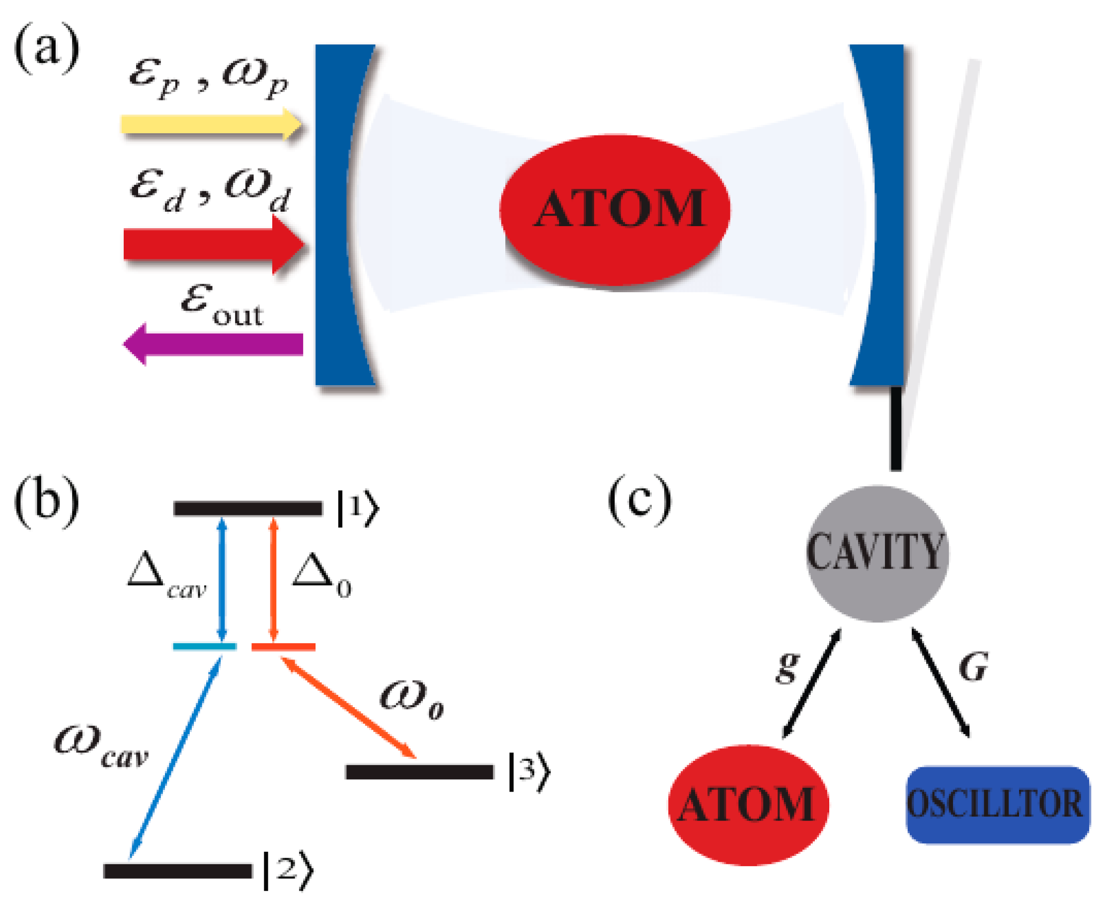
Figure 1. (a) Schematic diagram of a hybrid optomechanical system, which consists of a passive cavity system and an atom as well as an oscillator. The hybrid system is driven by a strong control field and a weak probe field through the passive cavity. (b) Schematic diagram of the internal energy level structure of an Λ -type three-level cold atom. (c) Atomic and mechanical oscillators coupled with the cavity field separately.
Photonics 11 00416 g001
Figure 2. (Color online) Calculation results of (a) the transmission | t p | 2 and (b) the efficiency of the second-order upper sideband η as a function of detuning δ / ω m for different values of the Rabi frequency Ω . The other system parameters: κ a = 2 π MHz , ω m = ω p l = 2 π × 50   MHz , γ m = 0.01   κ a , C = 100 , g = κ a , λ a = 532   nm , P d = 300   μ W , Δ a = Δ b = ω m .
Photonics 11 00416 g002
Figure 3. (Color online) Calculation results of (a) the transmission | t p | 2 and (b) the efficiency of the second-order upper sideband η as a function of detuning δ / ω m for different values of optomechanical cooperativity C . The other system parameters: κ a = 2 π MHz , ω m = ω p l = 2 π × 50   MHz , γ m = 0.01 κ a , g = κ a , Ω = 2 κ a , λ a = 532   nm , P d = 300   μ W , Δ a = Δ b = ω m .
Photonics 11 00416 g003
Figure 4. (Color online) Calculation results of (a) the transmission | t p | 2 and (b) the efficiency of the second-order upper sideband η as a function of detuning δ / ω m for different values of coupling strength g . The other system parameters: κ a = 2 π MHz , ω m = ω p l = 2 π × 50   MHz , γ m = 0.01 κ a , C = 10 , Ω = 2 κ a , λ a = 532   nm , P d = 300   μ W , Δ a = Δ b = ω m .
Photonics 11 00416 g004
Figure 5. (Color online) Calculation results of (a) the transmission | t p | 2 and (b) the efficiency of the second-order upper sideband η as a function of detuning δ / ω m . The other system parameters: κ a = 2 π MHz , ω m = ω p l = 2 π × 50   MHz , γ m = 0.01 κ a , C = 0.01 , g = 0.00015 κ a , Ω = 2 κ a , λ a = 532   nm , P d = 300   μ W , Δ a = Δ b = ω m .
Photonics 11 00416 g005
Disclaimer/Publisher’s Note: The statements, opinions and data contained in all publications are solely those of the individual author(s) and contributor(s) and not of MDPI and/or the editor(s). MDPI and/or the editor(s) disclaim responsibility for any injury to people or property resulting from any ideas, methods, instructions or products referred to in the content.