1. Introduction
The study of optical effects at a tight focus of a coherent radiation field is a relevant and interesting problem, since all six components of the electric and magnetic field strength make approximately the same contribution to the field formation at the focus. The contribution of any field components cannot be neglected, and the paraxial approximation cannot be used. Therefore, many interesting optical effects are known at a tight focus: optical wheels [
1,
2], polarizing Mobius strips [
3,
4,
5,
6], intensity zero nodes [
7,
8,
9], reverse energy flow [
10,
11], magnetization [
12,
13,
14], spin–orbital conversion [
15,
16,
17], and spin [
18,
19,
20] and orbital [
21,
22,
23,
24] Hall effects. Let us look at these effects in a little more detail.
“Photon wheels” [
1,
2] are formed at the focus due to transverse spin angular momentum, when the longitudinal component of the electric field has a phase delay of π/2 with one or two transverse components. In this case, the rotation ellipses of the polarization vector lie in the meridional plane, which is formed by the optical axis and one of the transverse Cartesian axes. The rotation of the polarization vector in the meridional plane during beam propagation resembles the rotation of a wheel.
Möbius strips are three-dimensional structures consisting of a surface with only one side. These structures, which can be easily demonstrated by cutting a paper strip, adding a twist, and then joining again ends of the paper, have intriguing mathematical properties in terms of topology and geometry. The authors of [
3] used a liquid crystal q-plate to create a given wavefront of a laser beam and to obtain an optical version of a Möbius strip by effectively “cutting and twisting” the polarization properties of a light beam at a tight focus. And then, using the method of three-dimensional nanotomography of optical vector fields, they completely reconstructed the structure of the light polarization in the focal region and confirmed the appearance of Möbius polarization strips. Also, different shapes of a Möbius polarization strip were obtained at the focus in [
4]. In [
5], the authors experimentally investigated polarization topologies similar to Möbius strips by exploiting an amplitude and phase reconstruction technique. A non-collinear superposition of two unfocused paraxial light beams in orthogonal states of circular polarization was considered in [
6]. One beam was an optical vortex, and the other one was a plane wave. The authors theoretically and experimentally confirmed the formation of many-turn Möbius strips or twisted ribbons when the topological charge of one of the component beams was odd or even, respectively.
The theory of nodal photonic structures was developed in [
7,
8]. In [
9], the nodes of intensity zeros (phase or polarization singularities) at the focus were considered. For nodal structures approaching the wavelength scale, longitudinal polarization effects become significant, and the electric and magnetic fields differ, resulting in intertwined nodal structures in the transverse and longitudinal polarization components, which are called a nodal beam of polarization singularities. In [
9], their structure is analyzed using polynomial beam approximations and numerical diffraction theory.
In [
10], by comparing the numerical and experimental intensity distributions at the tight focus of an optical vortex with topological charge 2 and left-handed circular polarization, the diameter of a “tube” with a reverse flow of light energy was determined. The diameter of the reverse energy flow tube along the optical axis was about 300 nm for the case of a numerical aperture of 0.95 and a wavelength of 532 nm. It has also been shown experimentally that when a beam with second-order cylindrical polarization is focused by a lens with a numerical aperture of 0.95, a circularly symmetric energy flow with very weak intensity in the center (Arago spot) appears at the focus. This Arago spot is formed as a result of diffraction of the forward energy flow at the boundary of the reverse energy flow tube. Formation of the photonic nanojet with energy backflow was considered in [
11].
The effect of optical magnetization at a tight focus was considered in [
12,
13,
14]. It is highly desirable for all-optical magnetic recording to have a focal spot with pure longitudinal magnetization. In [
14], a metalens is considered that has the triple functions of an azimuthal polarization converter, a helical phase plate, and a focusing lens. The three-in-one combination allows linearly polarized incident light to be converted into a first-order vortex beam with azimuthal polarization and focused into a diffraction-limited spot. The polarization state of the focal spot is measured as net circular polarization, which means that the net longitudinal magnetizing field can be induced by the inverse Faraday effect. The lateral width of the focal spot at half maximum is 1.9 μm, and the experimental metasurface conversion efficiency is about 19%.
The effect of spin–orbital conversion at a tight focus was theoretically considered in [
15,
16,
17]. It was shown in [
16] that the longitudinal component of the spin angular momentum is maximum on the optical axis in a strong focus of a Gaussian beam with circular polarization, and the longitudinal component of the orbital angular momentum is maximum on the ring. Thus, it is possible to evaluate the influence of the spin angular momentum and the orbital angular momentum on the movement of the captured microparticle separately. The spin–orbital transformation was experimentally demonstrated for a Gaussian beam with circular polarization, when a transverse energy flow (i.e., an orbital angular momentum) arises at the focus, which is transferred to the microparticle and causes it to rotate. The spin–orbital conversion also occurs when light passes through a metalens [
17].
The photonic Hall effect was first discovered when linearly polarized light passed through a multilayer micro-cavity [
18]. The spin [
19] and orbital [
20] Hall effect at a tight focus is that the initial light field has a zero-spin angular momentum, while at the focus there appear spatially separated regions in which the spin angular momentum or the orbital angular momentum have different signs [
21,
22,
23,
24], that is, photons with a spin of a different sign and a topological charge of a different sign appear at the focus. A lot of studies on the spin Hall effect at the focus have recently appeared. For example, it is shown in [
25] that after the focusing and propagation of a conventional linearly polarized Gaussian beam in free space, regions with left and right elliptical polarization appear in the beam cross section. In [
26], the geometric spin Hall effect is considered. This effect manifests itself when a light field with transverse angular momentum is formed at the focus, which leads to a displacement of the focal spot. In [
26], a light beam with left and right circular polarization was spatially separated in the initial plane to obtain a field with the transverse angular momentum at the focus. The authors of [
27] used a multifocal metalens to form the spin Hall effect. If such a metalens is illuminated by the linearly polarized light, several beams with left-handed circular polarization and right-handed circular polarization will be formed at the focus. In [
28], a review of modern work on the optical Hall effect is given.
In this paper, we continue to study the spin Hall effect at a tight focus. Previously, in [
21], we showed that four regions with spins of different signs are always formed at the tight focus of an optical vortex with topological charge
n and linear polarization regardless of number
n. In this study, we will show that if an optical vortex with linear polarization is coherently added to a plane wave that also has linear polarization (both linear polarizations are in the same direction), the number of regions with spins of different signs in the focal plane will increase with increasing topological charge of the optical vortex. The theory in this research is based on the Richards–Wolf formalism [
29], which adequately describes the strength of a monochromatic electromagnetic field near a tight focus.
2. Theoretical Foundations
Consider an initial light field, the Jones vector of which has the form:
where (θ, ϕ) are polar and azimuthal angles, defining a point on a sphere whose center lies at the focus,
n is the topological charge of an optical vortex,
a is a constant,
A(θ) is an amplitude of the initial light field depending only on the polar angle θ, which is related to the radial variable (
r =
fcosθ), and
f is a focal length of the spherical lens. It is clear from Equation (1) that the initial light field is a superposition of an optical vortex with linear polarization and a plane wave also with linear polarization. Therefore, each projection of the electric field strength vector near the focus will also be a superposition of two fields: an optical vortex with linear polarization and a plane wave with linear polarization. These projections can be taken from [
21,
29,
30], respectively. Then, according to the Richards–Wolf formalism, we obtained at the focus of the field (1):
In Equation (2), quantities
Iν,μ denote integral functions that depend only on the radial variable, in which the first index is the type of integral (ν = 0, 1, 2), and the second index (µ = 0, ±1, ±2, …) is equal to the order of the Bessel function
Jμ(ξ) under the integral:
where
k = 2π/λ is the wave number of light with the wavelength λ,
f is the focal length of a spherical lens, (
r, ϕ,
z) are cylindrical coordinates, θ
0 is the maximum inclination angle of rays to the optical axis, which determines the numerical aperture of the aplanatic lens NA = sin(θ
0), and ξ =
kr sin(θ).
Using Equation (2), an expression for the intensity distribution in the focal plane can be derived:
In the formulas in Equation (4),
I0 is the intensity at
a = 0, which coincides with that previously obtained in [
21]. Since Equation (4) includes a term with
I0,0, the intensity at the center of the focal plane will be different from zero for any
n, and the central intensity maximum will be extended along the
x axis, parallel to the initial polarization direction. This is determined by the dependence of main terms with the highest contribution to the intensity with the factor cos2ϕ, which has two positive maxima at the angles ϕ = 0 and ϕ = π. It is clear from Equation (4) that the intensity has a different form for even and odd numbers
n. Moreover, for even
n = 2
p, the intensity pattern is centrally symmetric, since arguments of trigonometric functions included in the transverse intensity are even functions; therefore, trigonometric functions themselves do not change sign when ϕ is replaced by ϕ + π. And the expression for the longitudinal intensity includes products of cosines with odd arguments, which also do not change sign when ϕ is replaced by ϕ + π. Since Equation (4) for
n = 2
p does not change when ϕ is replaced by −ϕ, the intensity pattern is symmetrical about the horizontal axis. And since the pattern is axisymmetric, it is also symmetrical about the vertical axis. The intensity pattern with an odd topological charge
n = 2
p + 1 will only have symmetry about the vertical Cartesian axis, since its value does not change when ϕ is replaced by π–ϕ. The number of main local intensity maxima, where the light energy mainly falls, can be determined based on the approximate equation, taking into account only the “main” terms in Equation (4):
Equation (5) includes only squares or products of integrals (3) with the first zero number, because it was shown in [
30] that the main contribution to the light field at the focus is made by terms with the first number zero in integrals (3). It can be seen from Equation (5) that the number of side lobes of the intensity pattern will be
n, since the cosine will change sign
n times over the period.
Using Equation (2), an expression for the longitudinal projection of the spin angular momentum according to the formula can be obtained:
Substituting Equation (2) into Equation (6), we obtain:
It can be seen from Equation (7) that if
a = 0, the longitudinal projection of the spin angular momentum coincides with the spin angular momentum for an optical vortex with linear polarization [
21]. It is also clear from Equation (7) that the expression for the spin angular momentum will have a different form and symmetry for an even or odd
n. When
n is even, the spin angular momentum (7) will have central symmetry, since under the sines and cosines the angle ϕ will be multiplied by an even number; therefore, when replacing ϕ with ϕ + π, the spin angular momentum pattern will not change. It is also clear from Equation (7) that replacing ϕ with −ϕ does not lead to a change in the spin angular momentum pattern. This means that the distribution of the longitudinal spin angular momentum is symmetrical about the horizontal axis. And since the spin angular momentum pattern is symmetrical about the horizontal axis and at the same time axisymmetric, it is also symmetrical about the vertical axis. When
n is odd, the spin angular momentum pattern (7) will be symmetrical only relative to the vertical axis. Since replacing ϕ by π-ϕ does not change the sign of sin(2
p + 1)ϕ, Equation (7) includes cos(
n + 2)ϕ for even
n or sin(
n + 2) ϕ for odd
n. Therefore, the maximum number of positive and negative spin angular momentum regions when traversing the beam cross section in a circle centered on the optical axis will be equal to 2(
n + 2), that is, the field (1) will have an even number of positive and negative areas with spins of different signs in the focus. This is due to the fact that, since the field (1) has a spin equal to zero (
Sz,0 = 0) in the initial plane, the total spin (the longitudinal component of the spin angular momentum averaged over the beam cross section at the focus) should be equal to zero at the focus:
This also follows from Equation (7), if it will be integrated over the entire focal plane. Terms from Equation (7), in which there are the trigonometric functions cosine and sine, will give zeros after integration over the angle ϕ and over the period. There will be a term from Equation (7) that does not have trigonometric functions:
Equation (9) follows from the result of integration over the radial variable
r of Equation (3), which was obtained in [
30]:
It can be seen from Equation (10) that the result of integrating Equation (3) does not depend on the second number, that is, on the number of the Bessel function. Therefore, the energy of terms and will be the same in Equation (9).
4. Results and Discussion
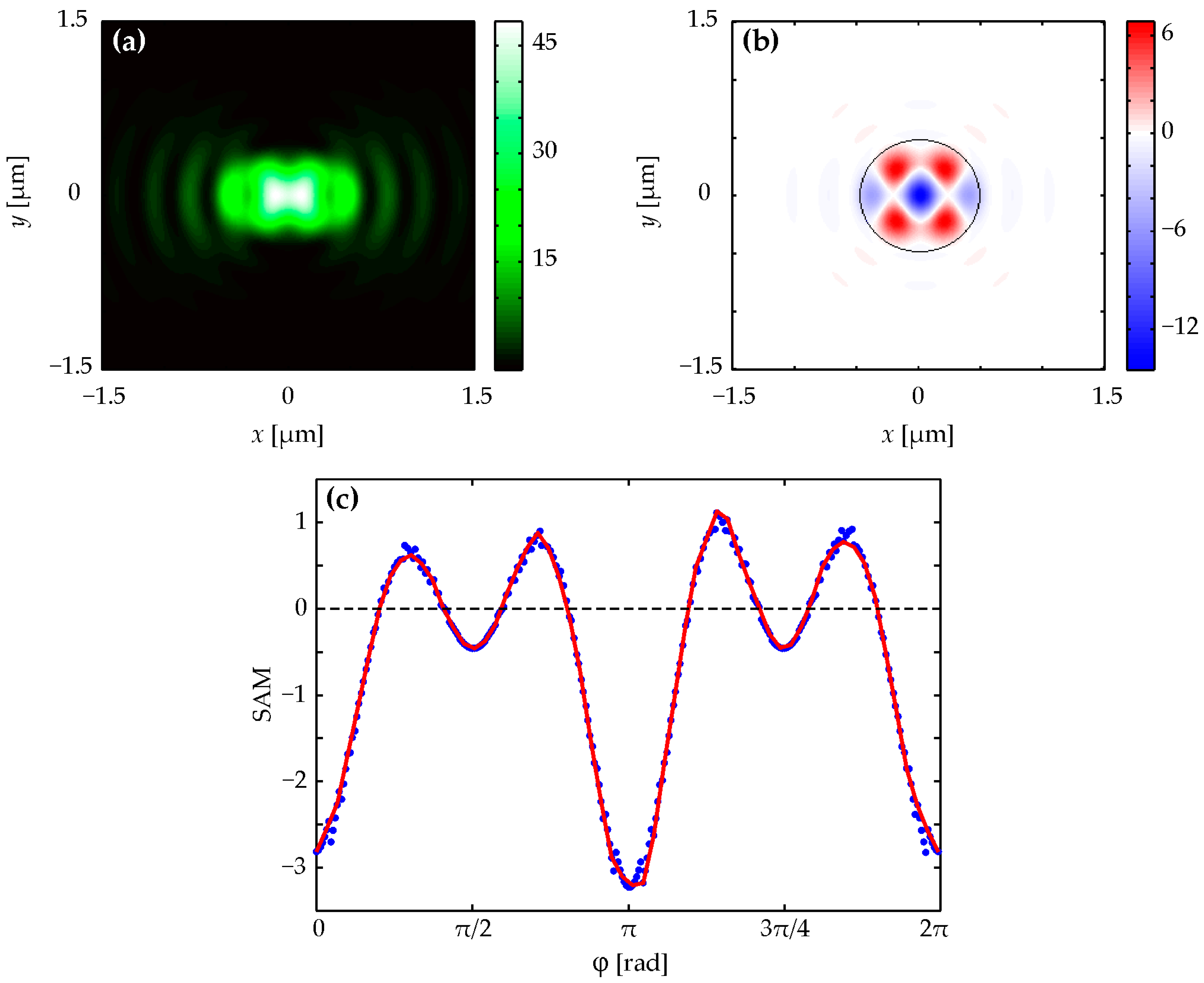
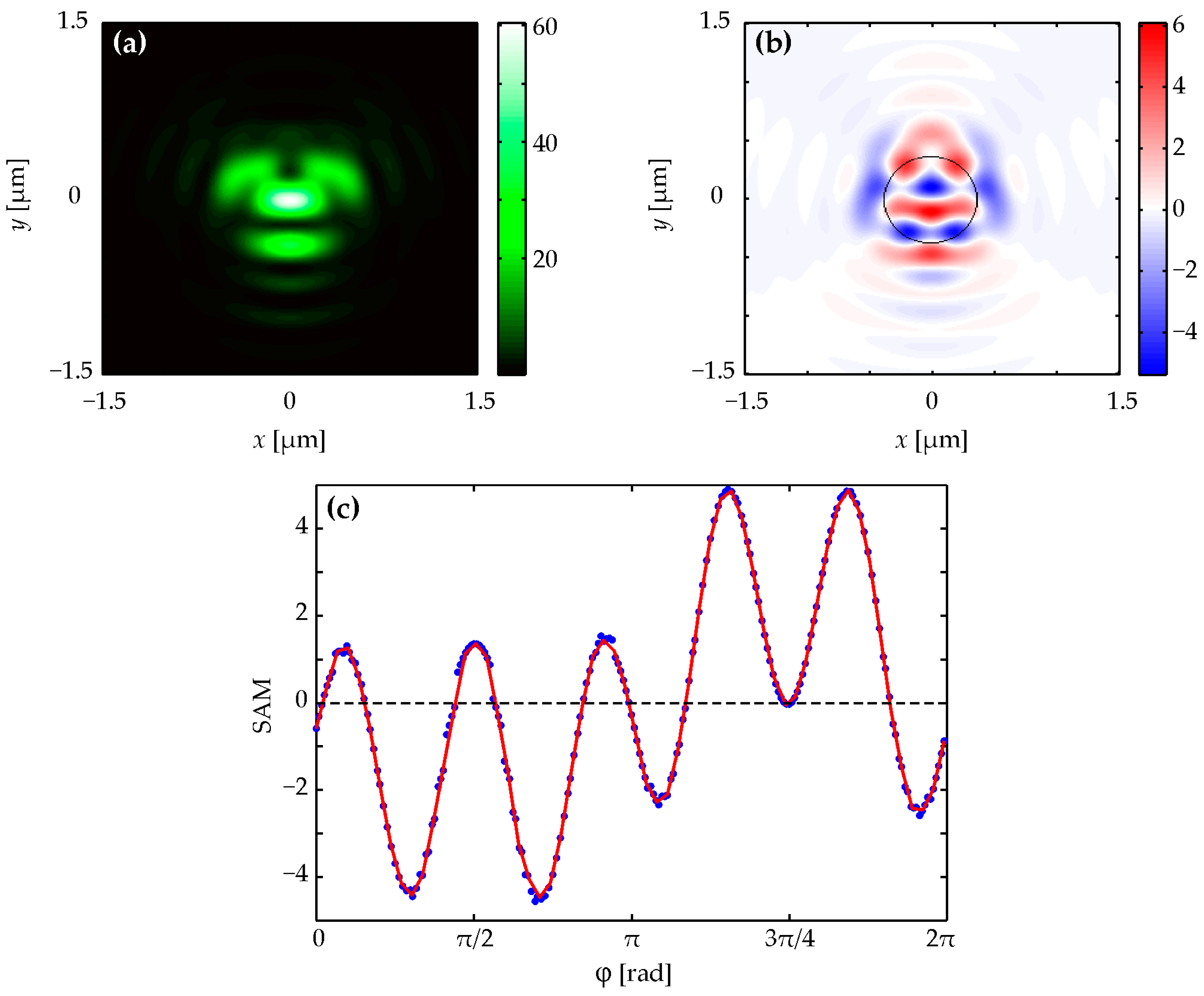
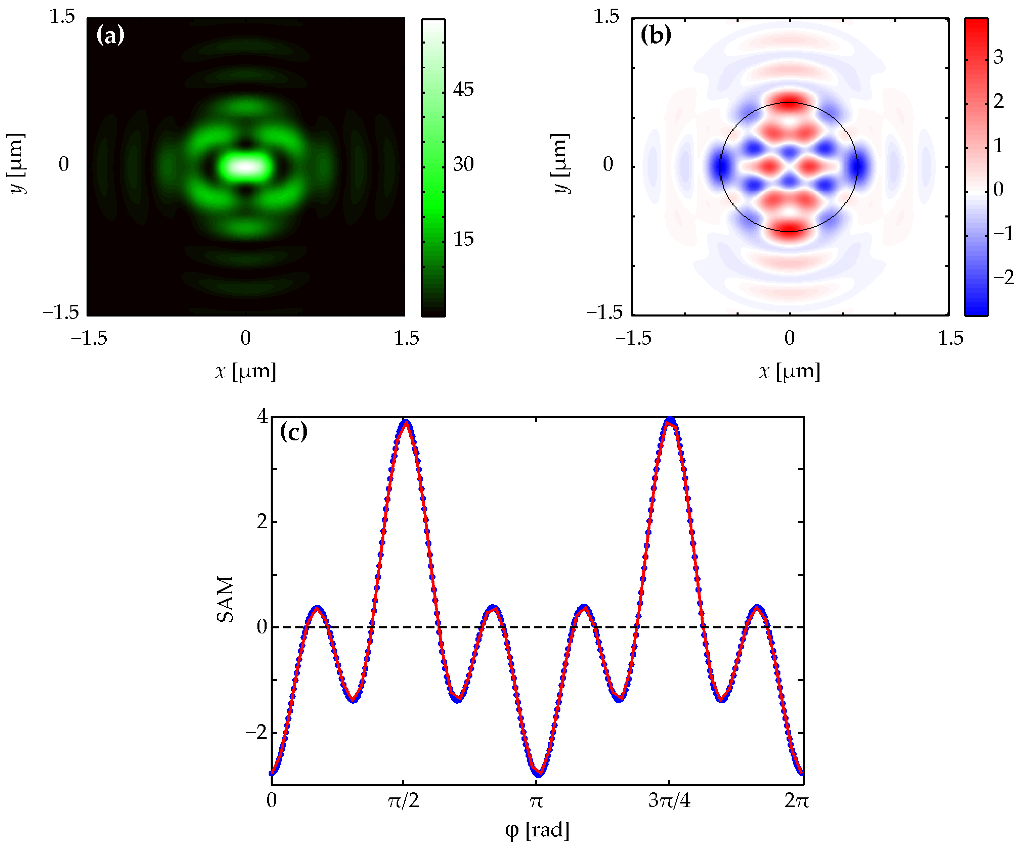
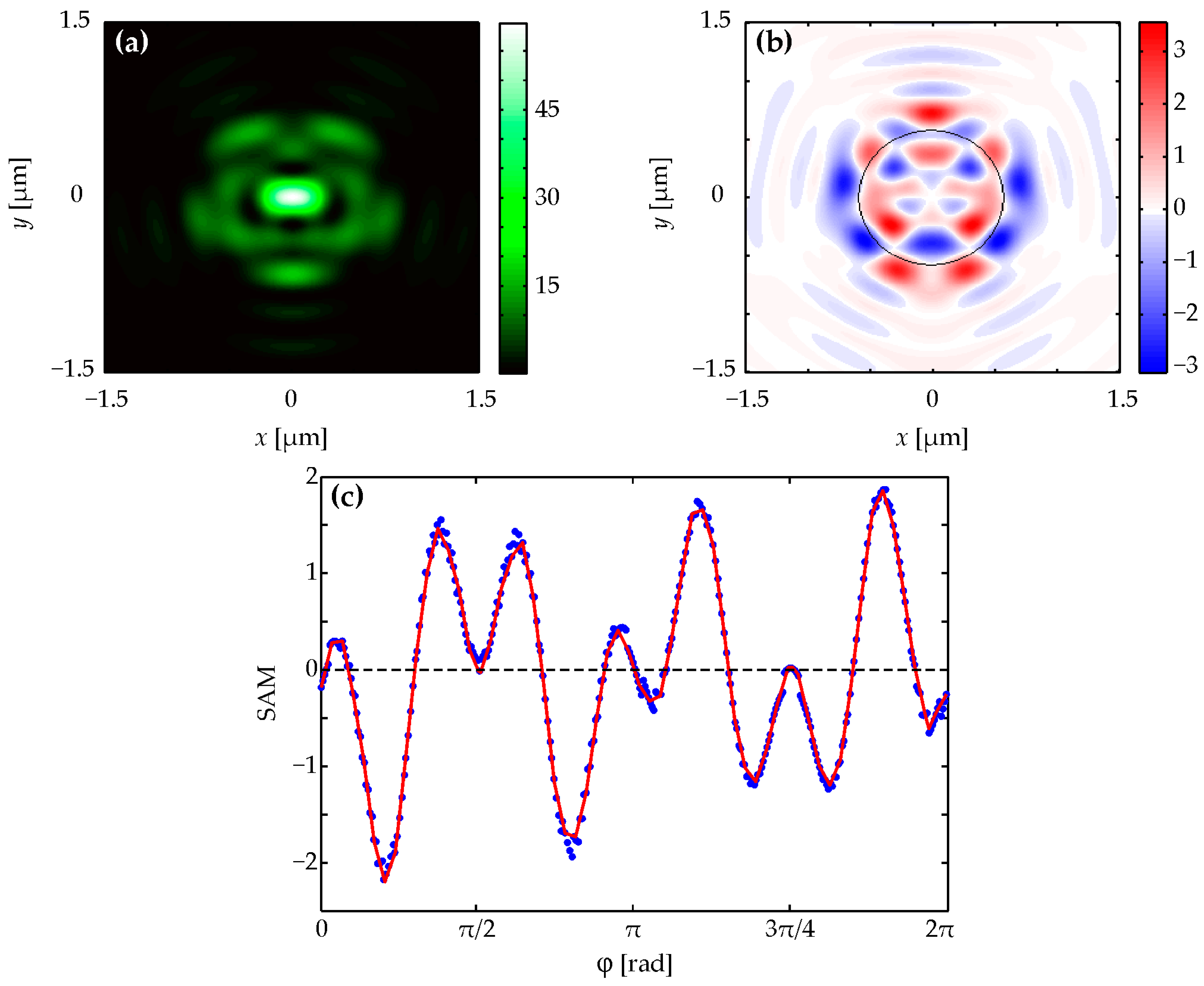
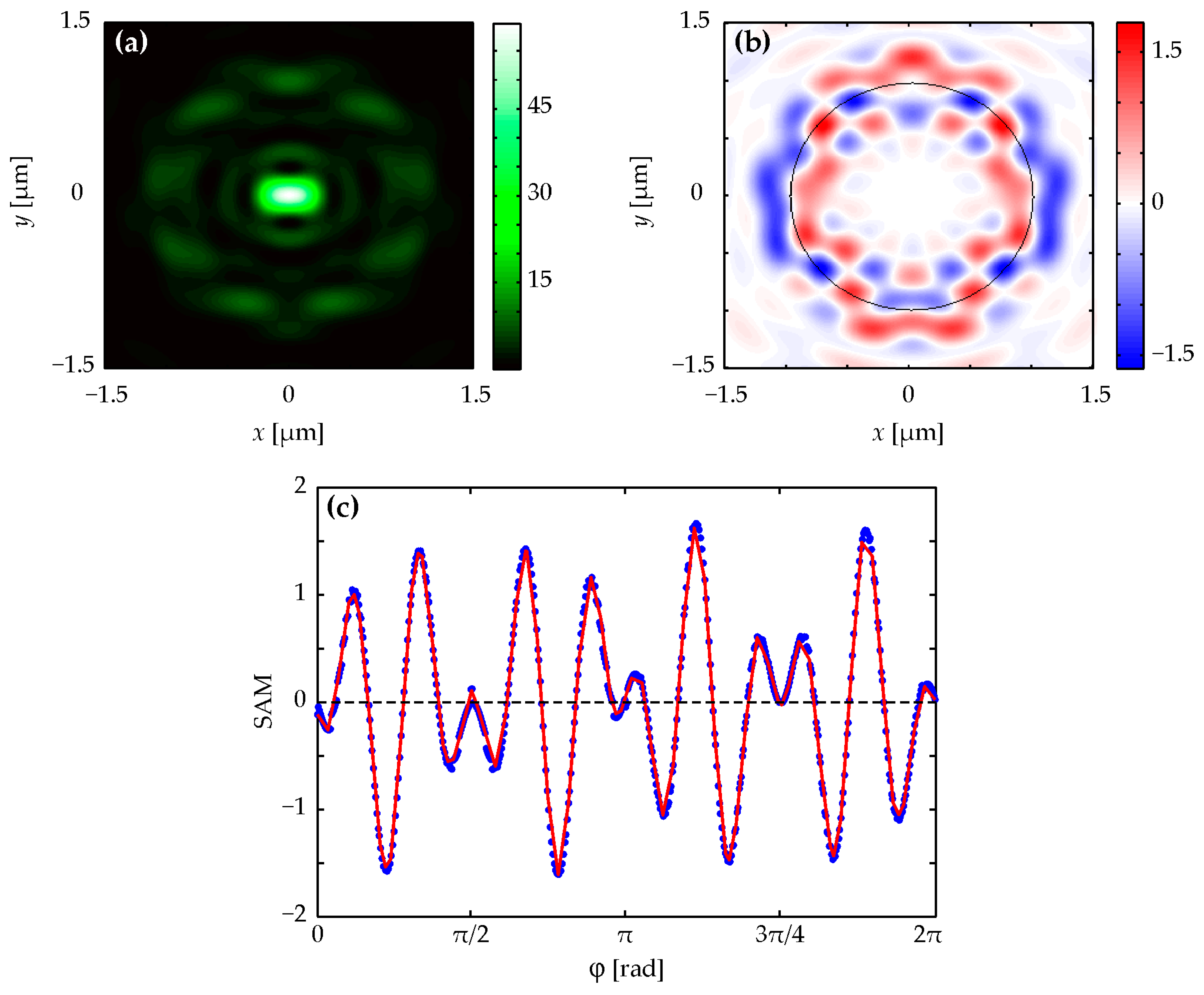
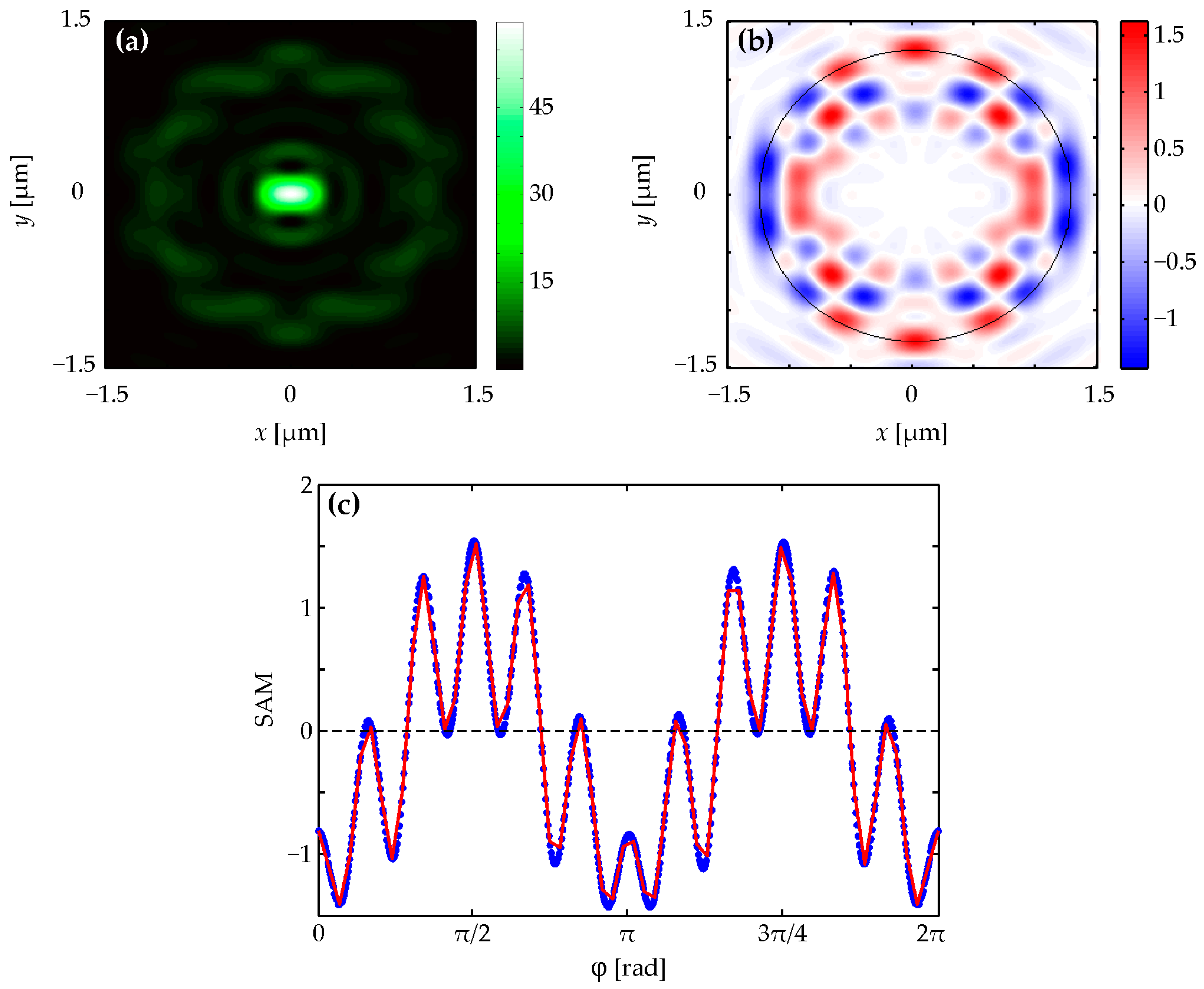
Figure 1a and
Figure 3a demonstrate that intensity patterns for
n = 2 and
n = 4 are symmetrical about both coordinate axes, and the intensities in
Figure 2a and
Figure 4a with
n = 3 and
n = 5 are symmetrical only relative to the vertical coordinate axis. This confirms the correctness of the expression for intensity (4), which has a different form for even and odd numbers
n. The number of local side lobes equal to
n = 2 (
Figure 1a), 3 (
Figure 2a), 4 (
Figure 3a), and 5 (
Figure 4a) can be counted in intensity patterns. It should be mentioned that the central intensity maximum should not be taken into account while calculating. This confirms the correctness of the simplified equation for intensity (5), in which there is a dependence on the azimuthal angle of the form cos(
nϕ + ϕ
0). This shows that the intensity will have
n local maxima when going around a circle of a certain radius.
Figure 1b,c and
Figure 3b,c demonstrate that the spin angular momentum density patterns for
n = 2 and
n = 4 are symmetrical about both coordinate axes, and the spin angular momentum density patterns in
Figure 2b,c and
Figure 4b,c with
n = 3 and
n = 5 are symmetrical only relative to the vertical coordinate axis. This confirms the correctness of Equation (7), which has a different form for even and odd numbers
n. By counting the number of red and blue spots in spin angular momentum distributions (they should be counted along the black dotted circle shown in the figures), we can be sure that the local areas where the spin angular momentum is positive and negative are equal to 8 (
Figure 1b,c), 10 (
Figure 2b,c), 12 (
Figure 3b,c), and 14 (
Figure 4b,c) according to the formula 2(
n + 2). This is consistent with Equation (7). Equation (7) includes cos(
n + 2)ϕ for even
n or sin(
n + 2)ϕ for odd
n. Thus, an increase in the topological charge
n of the field (1) by one increases the number of regions on the black circle in
Figure 1b,
Figure 2b,
Figure 3b and
Figure 4b by two (one region with a positive spin and one with a negative one). A similar comparison can be made for
Figure 5 and
Figure 6, which show the intensity and the longitudinal spin for the field (1) at
n = 9 (
Figure 5) and
n = 10 (
Figure 6).
Since the longitudinal component of the spin angular momentum coincides with the third Stokes component (i.e., with the projection of the vector which is perpendicular to the polarization ellipse at each point of the focal plane), the polarization vector rotates counterclockwise (right-handed elliptical polarization) in the red areas presented in
Figure 1b,
Figure 2b,
Figure 3b,
Figure 4b,
Figure 5b and
Figure 6b, and the polarization vector rotates clockwise (left-handed elliptical polarization) in the blue areas presented in
Figure 1b,
Figure 2b,
Figure 3b,
Figure 4b,
Figure 5b and
Figure 6b. Moreover, the type and magnitude of the polarization change near the optical axis changes with increasing
n > 0. There is a left-handed almost circular polarization near the optical axis in
Figure 1b (
n = 2). There are two smaller areas with left and right elliptical polarizations near the optical axis in
Figure 2b (
n = 3). There are already four regions with a smaller size near the axis in
Figure 3b (
n = 4). Two of them are with left and two are with right elliptical polarizations. And there is a linear polarization on the optical axis in
Figure 4b (
n = 5).
Figure 1c,
Figure 2c,
Figure 3c,
Figure 4c,
Figure 5c and
Figure 6c show projections of the longitudinal spin angular momentum onto circles of different radii, depicted by a black dashed line in
Figure 1b,
Figure 2b,
Figure 3b,
Figure 4b,
Figure 5b and
Figure 6b. By counting the number of positive and negative values of the spin angular momentum function in
Figure 1c,
Figure 2c,
Figure 3c,
Figure 4c,
Figure 5c and
Figure 6c, we find that there are eight positive and negative spin regions of different signs in
Figure 1c.
Figure 2c demonstrates 10 such areas, as well as
Figure 3c—12,
Figure 4c—14, and so on. Moreover,
Figure 1c,
Figure 2c,
Figure 3c,
Figure 4c,
Figure 5c and
Figure 6c allow us to judge whether the polarization in a given local focus area is elliptical, close to linear, or elliptical, close to circular. It can be determined by the magnitude of maxima and minima of different signs. Also, from a comparison of the colored bars in
Figure 1b,
Figure 2b,
Figure 3b,
Figure 4b,
Figure 5b and
Figure 6b, it is clear that at small
n, when there are few regions with spins of different signs, the polarization in them is close to circular. And as
n increases, the polarization becomes more and more elliptical, approaching linear.
5. Conclusions
In this paper, the following new results were obtained. The tight focusing of a combined laser beam, which is an axial superposition of two beams with the same linear polarization (an optical vortex with topological charge
n and unit amplitude and a plane wave with amplitude
a), is considered. Using the Richards–Wolf theory, analytical expressions for all three projections of electric field strength vectors, intensity and longitudinal spin angular momentum distributions in the focal plane were obtained. It is shown that the form and symmetry of intensity and spin angular momentum distributions depend on the parity of the topological charge
n. As the number
n > 0 increases, the number of side lobes in the intensity pattern and the number of regions with the positive and negative spin angular momentum increase. The presence of photons with spins of different signs in the focal plane is a manifestation of the spin Hall effect at the focus. Such distributions of the intensity and the spin angular momentum at a tight focus can be used for nanostructuring the surface of a material sensitive to polarization [
31,
32] and for magnetizing a material with different polarities based on the inverse Faraday effect [
33,
34]. Beams with complex polarization can also be used to structure surfaces [
35] and to form vector structured beams [
36]. Vortex waves and the spin–orbital conversion arise not only in free space but also in a nonlinear cubic media, including Bose–Einstein condensates [
37,
38]. However, as a rule, these studies proposed only scalar vortex waves (solitons) and the spin–orbital conversion, which is considered as the interaction of the particle spin with a magnetic field [
37,
38]. In our work, the spin–orbital conversion (although rather the opposite, the orbital–spin conversion) arises due to focusing using a spherical lens. We also note that the beams considered in this research form a different number of local regions with spins of different signs at the focus. If several dielectric micro- or nanoparticles with low absorption are captured in these regions, they will rotate in different directions (clockwise or counterclockwise) depending on the sign of the spin in this region [
39].
