1. Introduction
Laser absorption spectroscopy has become a powerful tool for gas detection in atmospheric sciences, industrial safety and protection, leakage identification, and many other applications because of the exceptional selectivity and sensitivity in the infrared spectral region [
1,
2,
3]. With the development of semiconductor lasers, narrow linewidth lasers can operate at specific wavelengths by adjusting the injection current or operating temperature, and accurate measurements can be achieved by scanning the absorption lines of the gas [
4]. Among them, tunable diode laser absorption spectroscopy combined with the wavelength modulation technique (TDLAS-WMS) is a common method in trace gas sensing. It can significantly improve the signal-to-noise ratio (SNR) relative to the direct absorption method since the noise at other frequencies is not analyzed. In addition, WMS is a convenient method for the continuous monitoring of gases because the amplitude of even the harmonic signal is proportional to the gas concentration within the measurement path length [
5,
6]. However, conventional light–gas interaction platforms typically use large free-space gas cells as sensing elements. These cells are size-constrained and susceptible to degradation in the optical coatings due to ageing, which affects long-term stability [
7]. In contrast, optical transmission and remote detection capabilities based on optical fibers can make the detection system more flexible and stable [
8].
Due to the unique ability to guide light with low loss in a hollow core, the hollow-core fiber (HCF) overcomes the limitations of conventional solid silica fibers associated with high dispersion, damage thresholds, non-linear effects, and maximum operating wavelength ranges. HCFs are paving the way for a variety of new applications for glass-based fibers [
9]. Based on the wide application of HCFs in gas sensing, many studies have been conducted on the flow characteristics of gases within the fiber. Under free-diffusion conditions, the inflation process of a 1 m long HCF typically takes several hours. The time required for the gas to enter the hollow core of an HCF depends on several factors, including the gas inlet pressure, the fiber core diameter, the fiber length, the gas viscosity, etc. [
10,
11,
12,
13]. To open the gas inlet channel, Sahar et al. used a section of specially designed C-type fiber as a gas inlet, and fusion splicing between a single-mode fiber (SMF) and a photonic crystal fiber (PCF). During the experiment, the PCF was vacuumed through this gas channel at first, and then a gas mixture of acetylene (C
2H
2) and nitrogen (N
2) was released. The response time was approximately 20 min [
14]. Jaworski et al. reported a NO sensing experiment based on the TDLAS-WMS method. A 1.15 m long AR-HCF was used as a gas cell, the AR-HCF interface was placed in a pressurized environment, and the gas was quickly pressed into the fiber for detection, thanks to the large hollow core diameter of 122 μm of the AR-HCF. The filling time was less than 10 s with an overpressure of about 120 kPa. The results of long-term monitoring experiments show that the 20 ppbv detection limit is reached with an integration time of 70 s [
9]. Grzegorz et al. tested an overpressure ranging from 20 kPa to 400 kPa with a 7.5 m long AR-HCF; when they carried out the highly sensitive methane detection within the mid-infrared interband, the response times were 24 min (20 kPa) and less than 2 min (higher than 200 kPa). The diameter of the utilized AR-HCF was 41 μm [
15]. Jaworski also listed the ARHCF-based gas sensors’ performance, including the gas exchange time, fiber length, etc. [
6]. However, the differential pressure method poses challenges for hazardous gases as well as remote ambient gas measurements. Yang et al. used femtosecond laser micromachining to drill microchannels on the photonic-bandgap HCF (PBG-HCF). They successfully drilled 242 high-quality channels along the 2.3 m photonic-bandgap HCF with an average loss of less than 0.01 dB per channel. The response time was reduced to about 40 s under atmospheric pressure [
16]. Zhao et al. fabricated 34 microchannels along a 0.74 m long AR-HCF with a diameter of 56 μm to exchange gas; gas detection was carried out with mode-phase-difference photothermal spectroscopy, and the response time was 44 s [
17]. However, the optic fiber probe prepared in their method has less mechanical strength and introduces additional transmission loss.
In this paper, a near-infrared all-fiber remote gas passive detection strategy using an MH-ECF as the transmission fiber is proposed for the first time. The MH-ECF enables single-mode conduction while machining an air channel in the round center of the fiber, with the core in the cladding on the side of the hollow part. The AR-HCF at the remote end is used as a gas cell. The MH-ECF provides and conducts negative pressure, and the pressure is transmitted to the air core of the AR-HCF to form a negative pressure condition. The remote ambient gases can be inhaled into the AR-HCF to achieve gas detection. The experimental detection was performed with CO2 detection at an absorption line of 6330.83 cm−1 by using the TDLAS-WMS technique. The length of the MH-ECF used in the experiment was about 20 m, which is long enough to demonstrate the ability of remote sensing. The length of the AR-HCF after fabrication was measured with a measuring tape to be about 0.44 m (long enough for CO2 sensing and a convenient connection to both the gas chamber and the MH-ECF). Under the action of an air pump, the response time was about 456 s defined by t90, which is the time taken for the gas sensor to reach 90% of the final signal level, an improvement of about 30 times over free diffusion.
3. Fabrication Process and Experiment Results
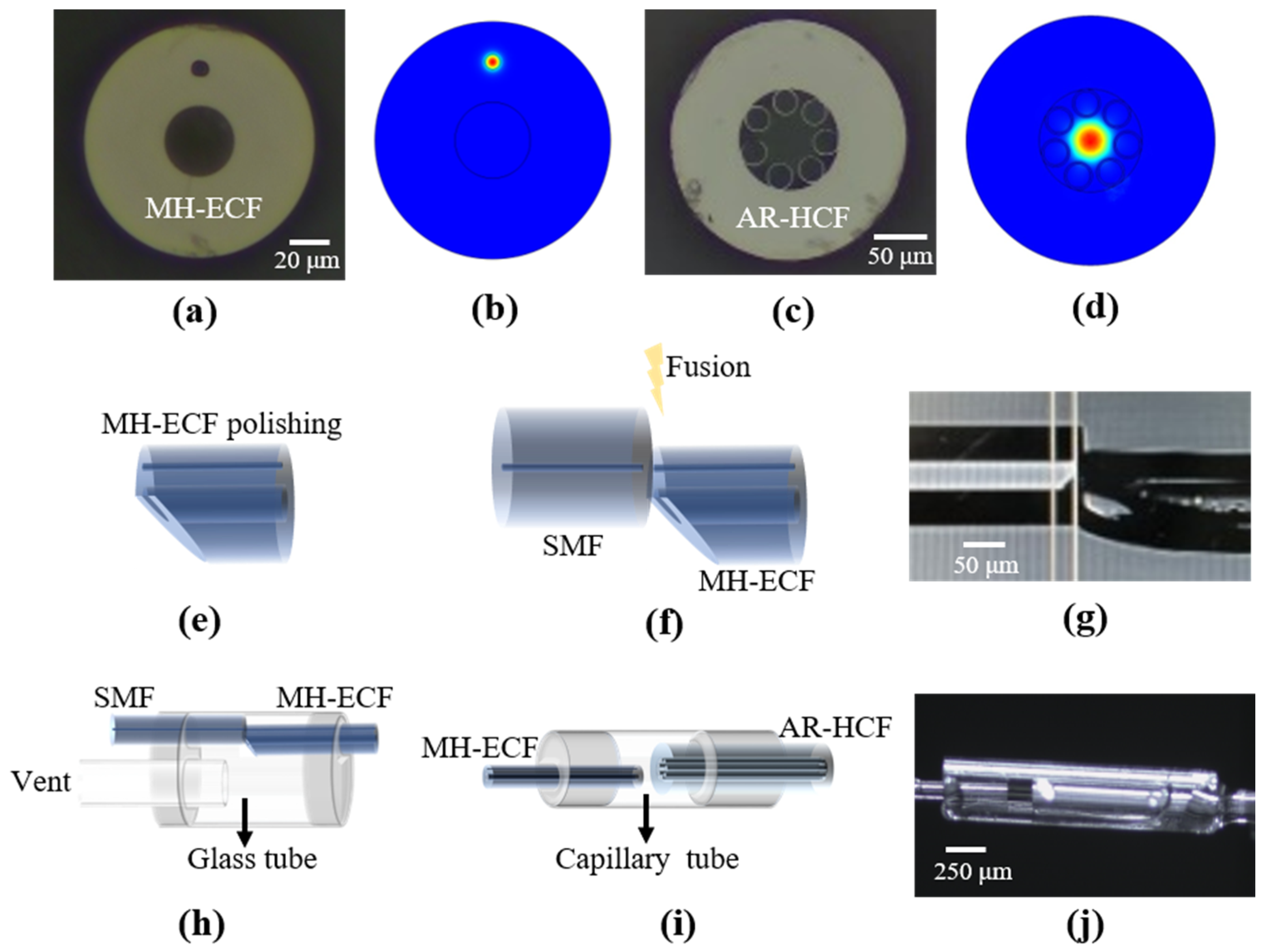
In this paper, an AR-HCF in the band near 1550 nm is used as a sensing gas cell. The transmission of light by an AR-HCF primarily depends on thin-wall capillaries with a diameter of approximately 26 μm which are inscribed on the inner wall of the quartz glass tube as illustrated in
Figure 1c. The inner cladding here is not a two-dimensional periodic structure and has no photonic bandgap. Light is guided in the hollow core by the principles of “anti-resonant” and “prohibited-coupling”. It has a mode field diameter of 37 μm and an outer cladding diameter of 199 μm. And we simulated the fundamental mode-field profile of the AR-HCF used in our experiments (to obtain the fiber end-face image shown in
Figure 1d) with COMSOL Multiphysics. Due to the smaller number of modes supported by an AR-HCF, generally single-mode or few-mode fibers, an AR-HCF could achieve better performance over a PBG-HCF, which was found to be primarily limited by multipath interference [
7,
24,
25]. However, an important issue in HCF-based gas sensors is how to introduce gas into the micron-sized hollow core. For the first time, the gas introduction is carried out by remote pumping in this paper. Among them, the remote conduction of the negative pressure difference is realized with a custom MH-ECF. The fiber structure is shown in
Figure 1a. While ensuring the single-mode conduction structure of the fiber, an air channel is processed in the cladding at the center of the fiber with a diameter of about 39 μm, and the core is in the cladding on one side of the air channel. The fundamental mode-field profile of the MH-ECF has also been simulated as shown in
Figure 1b.
In addition, the all-fiber RGS also includes two SMFs with FC/APC connectors, one of which is fusion splicing with a 20 m length MH-ECF, and the fusion interface is defined as interface 1 (IT1), which provides an extraction channel. Before fusion splicing, in order to open the ventilation path on the side of the MH-ECF, the air channel of the MH-ECF is opened by oblique polishing as shown in
Figure 1e [
26]. Power monitoring can be used to determine whether the cores are in alignment during fusion splicing. With the adjustment of the discharge magnitude and the time of the fusion splicer, the insertion loss of this interface is about 4 dB. IT1 is shown in
Figure 1f,g. Since IT1 needs to provide negative pressure, one end of the fiber can pass through a glass tube with an inner diameter of 4.6 cm before fusion. A vent tube is inserted into one side of the glass tube and sealed with Modified Acrylic Adhesive (302, Geliahao, Fushun, Liaoning, China) after fusion splicing, as shown in
Figure 1h. When pumping out from the vent tube, negative pressure can be provided at IT1.
The other end of the MH-ECF is connected to the AR-HCF with a length of approximately 0.44 m, whose connect interface is defined as interface 2 (IT2). IT2 serves to maintain gas flow within itself while being sealed from the external environment, ensuring the continuous transmission of the negative pressure difference. Due to the unique structure of both the AR-HCF and MH-ECF, fusion splicing directly results in a very narrow gas channel within IT2, which severely reduces gas flow. So that the MH-ECF and AR-HCF are inserted into a capillary tube with a 300 μm inner diameter as a sleeve, the alignment process is accomplished by a 3D fine-tuning stage. A minute quantity of UV adhesive (NOA63, Edmund Optics, Barrington, NJ, America) is drawn at the capillary port and sucked in by capillary action. To prevent any excess UV adhesive flowing into the hollow core of the fibers from the tips, timely activation of the UV curing lamp is essential. The cured structure is depicted in
Figure 1i. The insertion loss of IT2 after the curing process is approximately 5 dB, and the cured IT2 is shown in
Figure 1j. In addition, the implementation of the capillary sleeve enables the effective separation of the MH-ECF and AR-HCF, which can improve the optical coupling efficiency. Since the mode-field diameter between the MH-ECF and AR-HCF is different, as shown in
Figure 1b,d, it is necessary to keep a certain gap to ensure that the mode overlap integral is as large as possible [
27,
28,
29]. It should be noted that the curing process is performed with the help of a microscope.
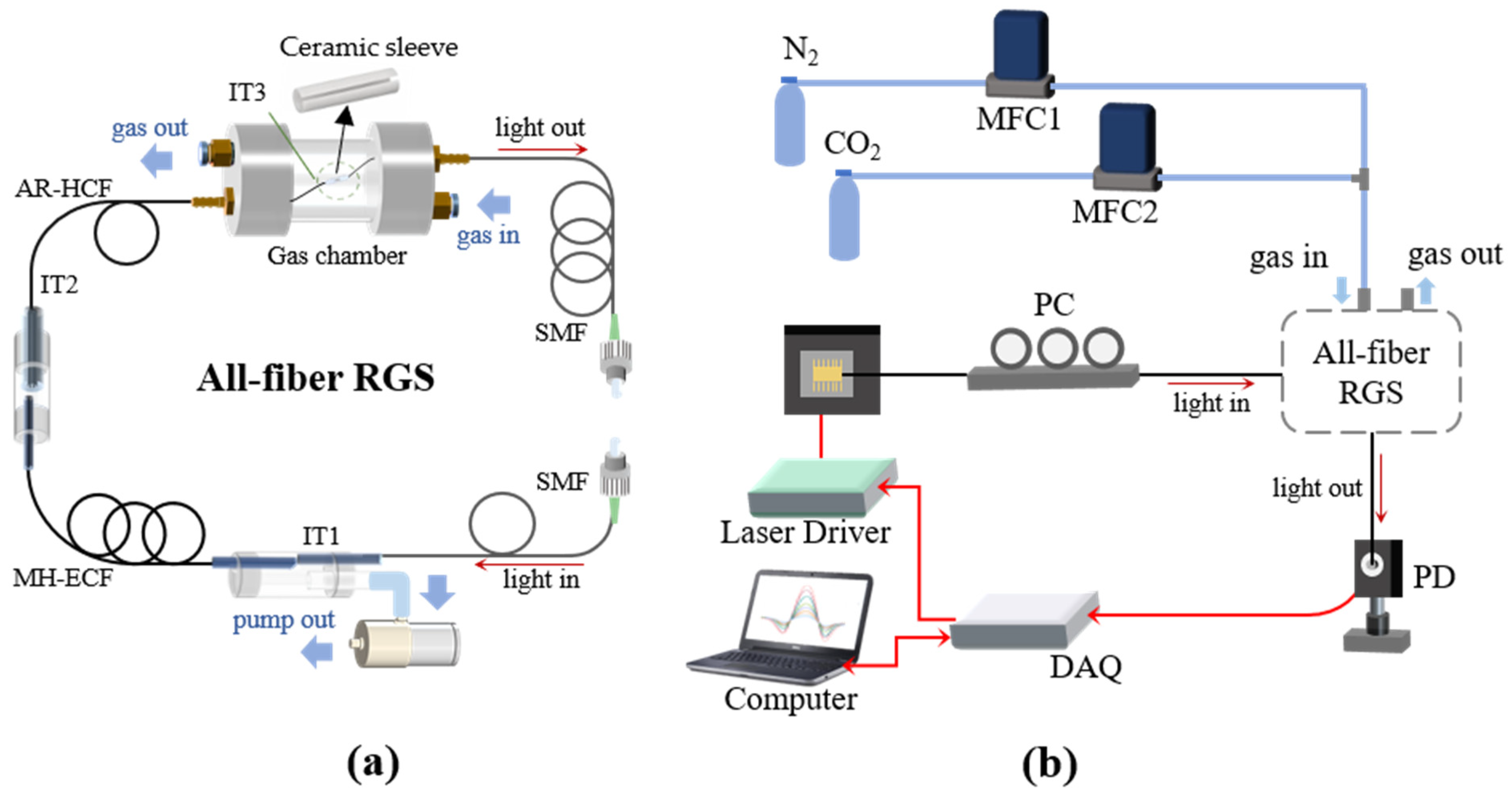
The other end of the AR-HCF is connected to another SMF, whose connect interface is defined as interface 3 (IT3) and is positioned in the test environment. The coupling is established with the ceramic ferrules and ceramic mating sleeve. A gap is left between the two-fiber end faces as a gas channel. After the connection of the three interfaces, the cumulative loss of all-fiber RGS amounts to approximately 14 dB. During the experiment, a detachable acrylic gas chamber is utilized as the test environment, as shown in
Figure 2a. The gas chamber consists of a spiral detachable top cover at both ends and a hollow cylindrical structure, with a pagoda joint and a fast connection-peg on each top. Before aligning the fibers, we pass the optical fibers through the pagoda joints on both sides first, then assemble the gas chamber, and seal the pagoda joints with the UV adhesive after coupling the fibers. The fast connection-pegs are the environmental inlet and outlet air passages. Since CO
2 is heavier than air, the lower position of the fast connection-peg is used as the inlet channel, and the higher one is used as the outlet channel.
The all-fiber RGS is illustrated in
Figure 2a, with FC/APC connectors employed at both ends to establish the connection between the laser and photodetector, and the three interfaces are also partially enlarged to show the entire connection condition more clearly. A pump (YL-6324, Dacheng Motor, Wenling, Zhejiang, China) is utilized to supply the negative pressure at IT1. To validate the efficacy of remote sensing, a 20 m MH-ECF is employed to produce negative pressure, thereby facilitating the suction of gas from the gas chamber into the AR-HCF, and the gas passive detection is achieved in the environment to be tested. The all-fiber RGS includes three ventilation pipes: the inlet and outlet pipes of the gas chamber at IT3, as well as the extraction pipe at IT1.
Figure 2b shows the schematic diagram of the carbon dioxide detection experiment. The absorption line at 6330.83 cm
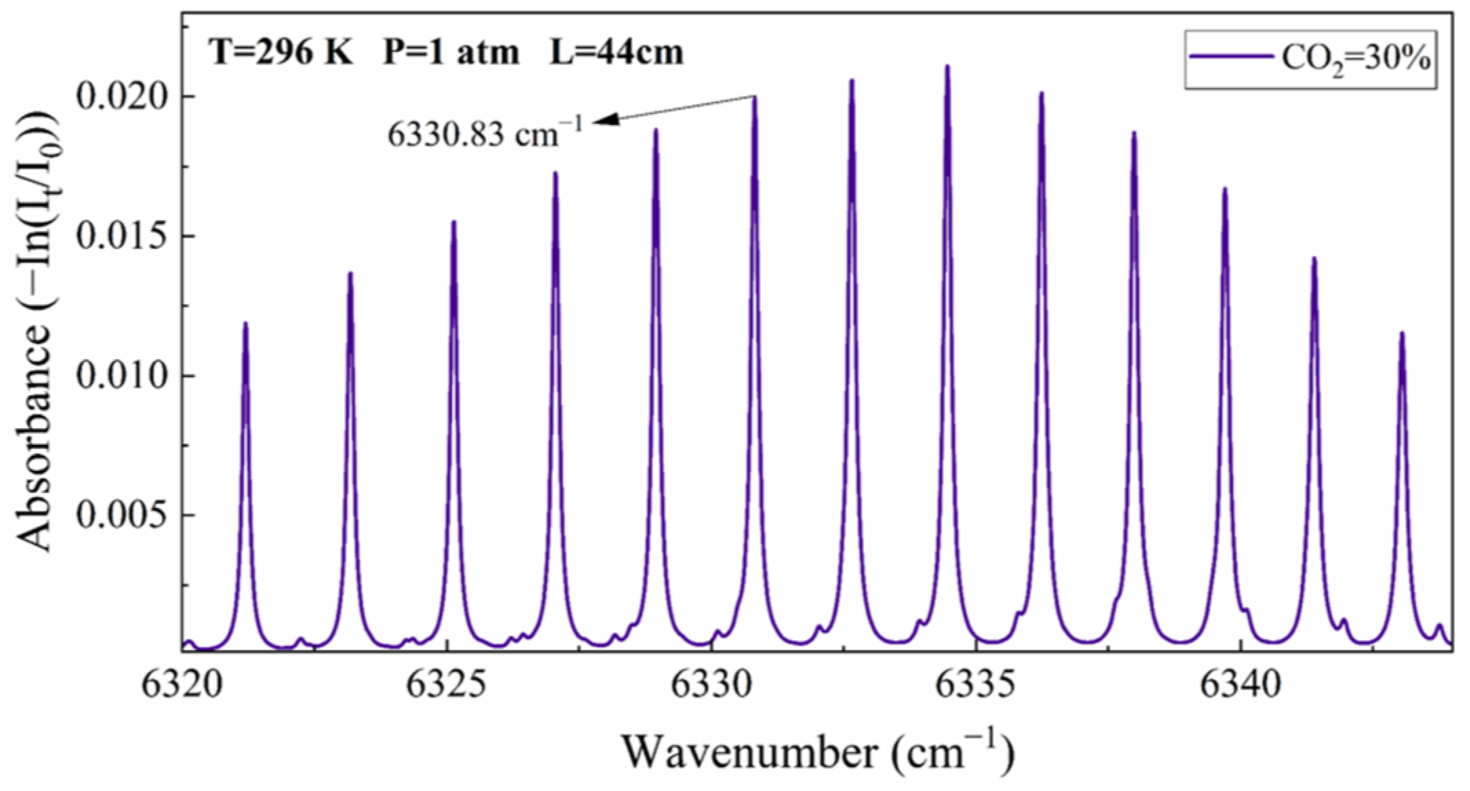
−1 could be effectively scanned by utilizing a 1580 nm CW-DFB (SWLD-1580, Sichuan Zhiyuanguang, Chengdu, Sichuan, China) according the HITRAN database and the parameters of the CW-DFB. The absorbance of 30% CO
2 around 1580 nm was simulated at a standard atmospheric pressure and temperature of 296 K with an effective optical path length of 44 cm, as shown in
Figure 3. The emitted light from the CW-DFB passes through a polarization controller and then is connected to the all-fiber RGS, and the transmitted light is received by the PD (PDA50B2, Thorlabs, Newton, NJ, USA), as shown in
Figure 2b. The program generates high-frequency sine wave and low-frequency triangular wave modulation signals, and transmits them via a data acquisition (DAQ) card (USB-6211, National Instrument, Austin, TX, USA) to the drive current of the laser driver (ITC102, Thorlabs, Newton, NJ, USA). The modulation frequencies are 9015 and 2 Hz, respectively. The optical signals received by the PD are converted into electrical signals and subsequently transmitted to the DAQ card for further processing. The acquired signals undergo demodulation using a digital lock-in amplifier [
30,
31], and the second harmonic (2f) signals can be acquired. The environment to be tested is constructed within the gas chamber, which is accomplished by a pair of mass flow controllers (MFCs) that control the flow rate of CO
2 and N
2, respectively.
In order to validate the sensing capability of the all-fiber RGS, the experiments with different concentrations of CO
2 are carried out first. The full width at half maxima (FWHM) is approximately 0.05 nm for the absorption line at 6330.83 cm
−1, the maximum amplitude of 2f can achieved when setting the modulation depth at 70 mV, and the current response coefficient of the laser drive is 40 mA/V [
23].
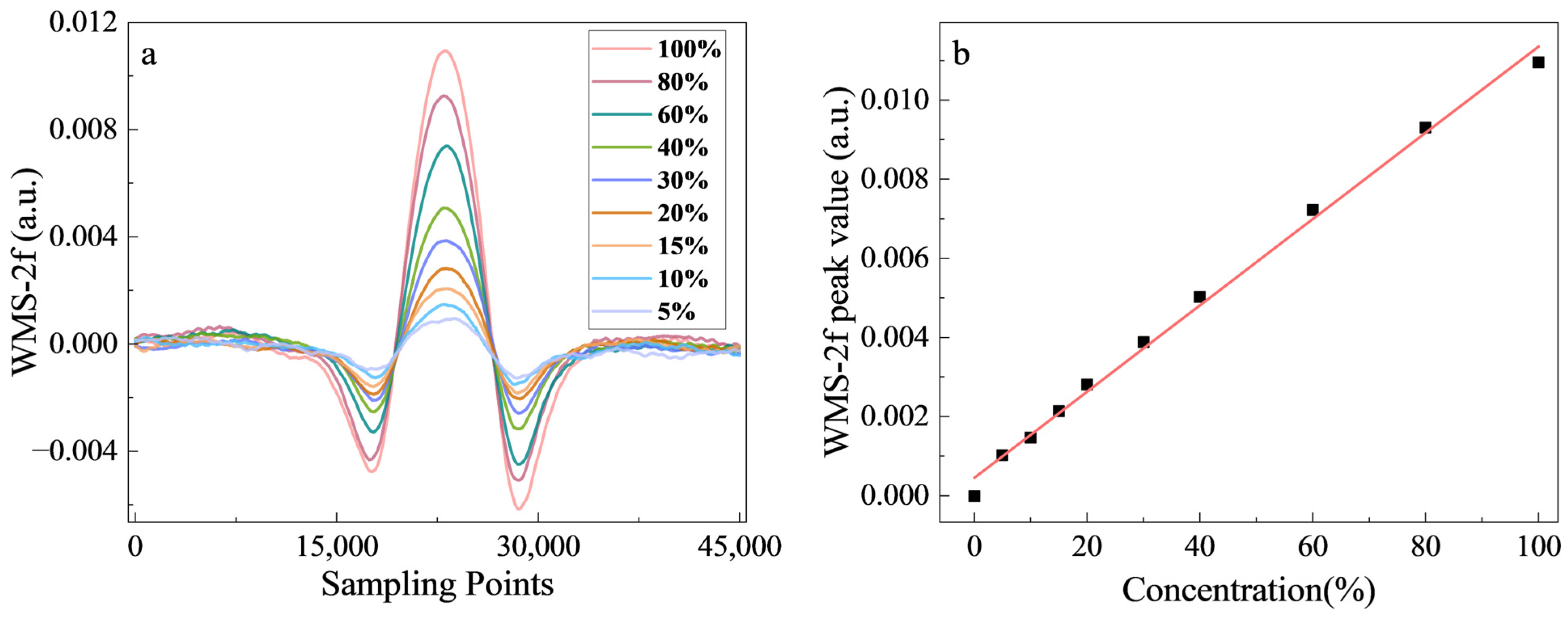
Figure 4a shows the demodulated WMS-2f signals of different concentrations of CO
2. During the experiment, we keep the total flow rate of MFCs working at 100 mL/min. The pressure variation between the gas chamber and the atmospheric environment is about 0.04 kPa under the flow rate, which is recorded by a pressure sensor (DLX-DMG512C, DELIXI, Leqing, Zhejiang, China). The varying concentration of CO
2 is achieved by adjusting the flow rate ratio of the MFCs. A triangular wave frequency of 2 Hz is utilized, and the record period and average time of the peak value of the WMS-2f signal are once and twice per second. The linear response of the all-fiber RGS is depicted in
Figure 4b, which is obtained by averaging 200 recordings for each concentration. The linear relationship is y = 1.09027 × 10
−4x+ 4.54997 × 10
−4. Although the detected CO
2 concentration is high, the determination coefficient (R-squared value) for the linear fit remains at 0.99545. The reason is that the absorption line has a small absorption cross section, the sensing fiber is relatively short, and the weak absorption condition
σNL << 1 is approached, where σ is the absorption cross section of CO
2 at the corresponding frequency,
N represents the molecular number density of the gas, which is directly related to the gas concentration, and
L is the effective optical path length [
32,
33,
34]. However, a slight non-linear problem can still be seen at higher concentrations, as shown in
Figure 4b. For this problem, the logarithm of the spectrum can be obtained to avoid the non-linear trend under strong absorption conditions [
35].
In addition, in order to verify the stability of the all-fiber RGS, long-term continuous monitoring is also carried out with 30% CO
2.
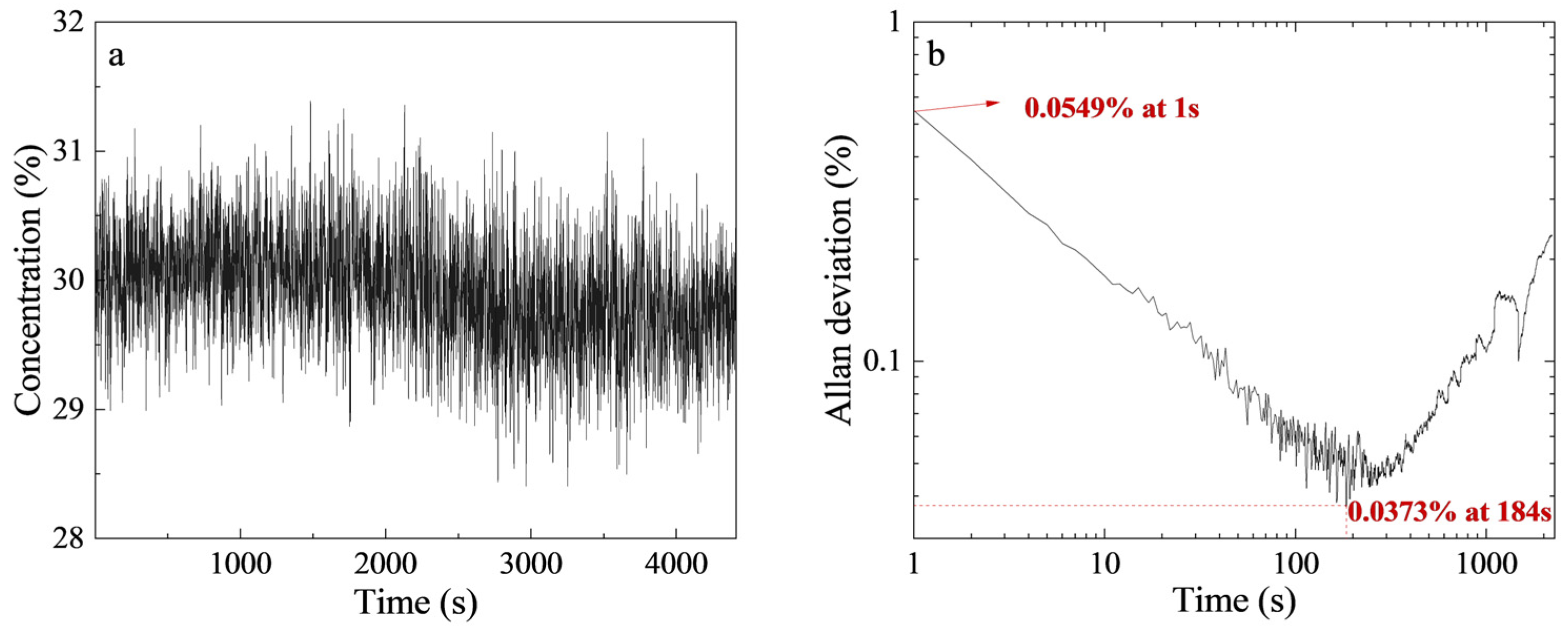
Figure 5a shows the specific fluctuation range of the concentration monitored over 74 min, including 4410 collected data points. The measurement error fluctuation is less than ± 3.3%.
Figure 5b shows the Allan deviation obtained in the above time period of continuous monitoring [
36]. The sensitivity of the all-fiber RGS is 0.0549% with an integration time of 1 s. The detection limit of the all-fiber RGS is 0.0373% with an integration time of 184 s. After 184 s, the standard deviation increases instead of decreasing, primarily because of the influence of drift noise [
30].
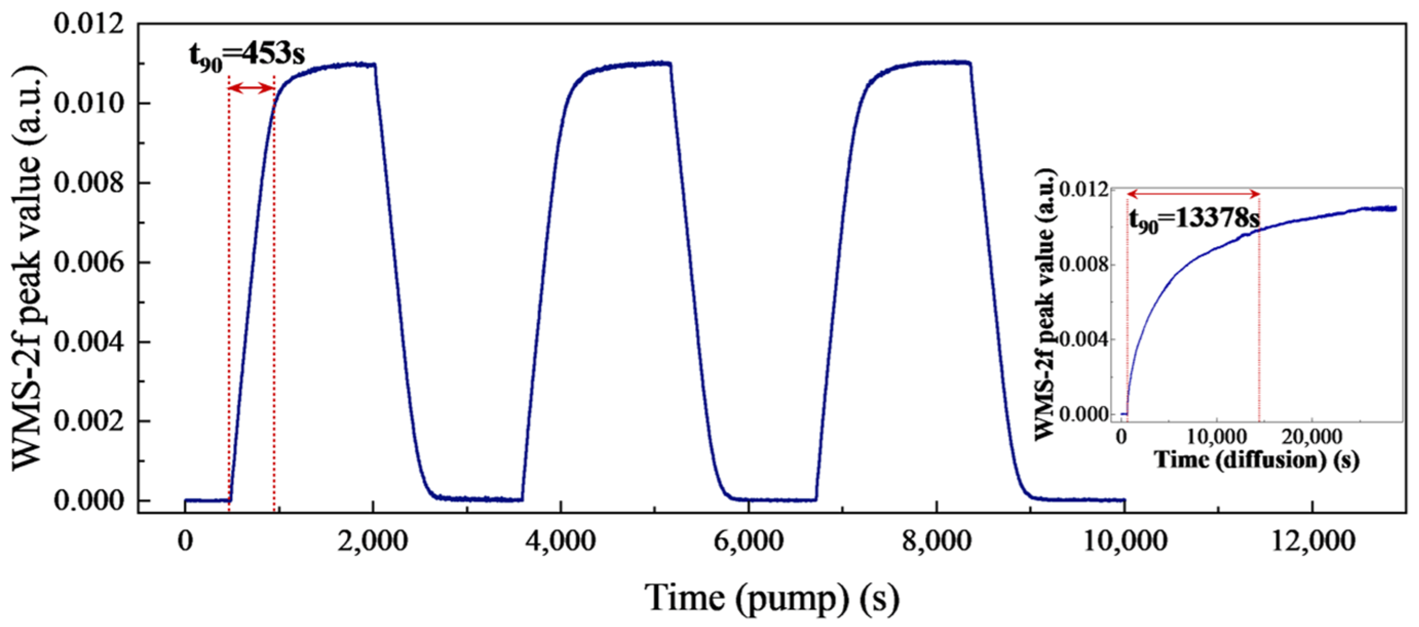
Additionally, different experiment conditions of air pumping at IT1 and free diffusion are utilized to validate the response time of the all-fiber RGS. In order to promptly establish a gaseous environment within the gas chamber, 100% CO
2 is initially employed at a 500 mL/min flow rate, resulting in a pressure differential of approximately 0.15 kPa between the gas chamber and the atmosphere. After maintaining the flow rate for 2 min, to minimize the impact of pressure and conserve standard gas usage, a flow rate of 100 mL/min is adopted. We continue ventilation at a differential pressure of approximately 0.04 kPa until the peak value of the WMS-2f signal reaches its plateau. The response time of continuous pumping at IT1 and the free diffusion of 100% CO
2 are tested while maintaining consistent conditions as mentioned above.
Figure 6 illustrates that the t
90 times are 453 s and 13,378 s, respectively, and the t
90 times of the other measurement cycles are 463 s, 459 s, 456 s, and 459 s. The average gas exchange time is about 456 s, meaning that the response time of continuous pumping at IT1 is approximately 30 times faster than that of free diffusion.
4. Discussion and Conclusions
HCF-based gas sensors have been widely studied recently due to their advantages of having a small size and the flexibility of their detection systems. However, in the process of application, the gas exchange time of free diffusion within the hollow core is very slow, even taking several hours, and detection timeliness is lost. Most of the current research accelerates the exchange of gas through pressure difference [
6,
9,
14,
15]. As a result, in addition to configuring the sensing fiber, the end face of the HCF should be sealed to increase or decrease the pressure in the actual detection period, which greatly increases the complexity of the detection system. And in the detection process of some flammable and explosive gases, the use of electricity will also induce potential safety hazards. In addition, there are some scholars who have used the femtosecond laser to fabricate holes to open the gas channels on the side of the HCF [
16,
17]; although this can improve the gas exchange speed, the mechanical strength is decreased and additional transmission loss is introduced.
The present study introduces a novel all-fiber remote gas sensing strategy with a pumped configuration for the first time. We demonstrate the feasibility of gas remote monitoring by utilizing a 0.44 m AR-HCF as the sensing fiber and a 20 m MH-ECF for conduction. The TDLAS-WMS technique is employed to validate the gas sensing performance of the structure. With the consideration of global climate change, the detection of CO2 was achieved. The remote ambient gases can be inhaled into the AR-HCF from 20 m away when the pump extracts the air in the hollow core of the MH-ECF at IT1. The response time t90 in the pumped state is approximately 456 s, exhibiting a remarkable acceleration of about 30 times compared to that of free diffusion. The sensitivity of the all-fiber RGS is 0.0549% with an integration time of 1 s. The detection limit of the all-fiber RGS is measured to be 0.0373% with an integration time of 184 s. Relevant research should be conducted to further improve the response time by optimizing the structural parameters of the MH-ECF, as well as the connection of each interface.
Although the response time of this structure remains comparatively slower than other pressurized ventilation methods directly applied at the end of the AR-HCF, it offers a means to centrally perform negative pressure treatment remotely, eliminating the need for employing an air pump at every probe port. This advancement significantly enhances the safety of detecting high-risk gases, such as flammable, explosive, toxic, and harmful gas, providing a practical and reliable solution for remote gas monitoring.
