Abstract
The full Poincaré (FP) beam, encompassing all possible polarization states in its beam cross-section, has demonstrated advantages in various applications. However, conventional FP beams are typically considered as spatially fully coherent, rendering them sensitive to disturbances in the propagation path and susceptible to speckle effects. In this work, we propose an alternative approach to synthesize the optical beam with a FP polarization state through the spatial coherence engineering of a partially coherent beam. In this process, the FP polarization state is initially encoded into the spatial coherence structure of the beam source. We demonstrate that during the encoding process, the vector nature of the beam transitions from the FP polarization state to the spatial coherence structure of the source. However, during the propagation of the partially coherent beam, the vectorness reverts to the polarization state, resulting in the re-emergence of the encoded FP polarization in the output plane. We illustrate that the synthesized FP polarization state, achieved through spatial coherence engineering, is highly robust against obstructions in the propagation path. Furthermore, we examine the effect of the spatial coherence area of the beam on the quality of the recovered FP polarization state. The findings of this work can have valuable applications in optical trapping and optical imaging in complex environments.
1. Introduction
Optical vector beams with spatially nonuniform polarization states have garnered significant attention over the past two decades due to their extraordinary properties, finding diverse applications such as optical imaging, optical trapping, and optical communications [,,,,,,,,,]. Among various vector beams, the full Poincaré (FP) beam stands out for its uniqueness, which presents all possible polarization states simultaneously on the Poincaré sphere within its beam cross-section []. The complex polarization distribution of the FP beam offers solutions for beam shaping [], optical trapping [], and polarimetry [,]. Moreover, studies have indicated that FP beams can notably reduce turbulence-induced scintillations []. The FP polarization state can be represented on a hybrid Poincaré sphere, with two eigenstates at the poles being the fundamental Gaussian mode and the Laguerre–Gaussian mode with opposite circularly polarized states [,]. Consequently, the FP polarization state can be synthesized using different types of interferometers [,,,,,,,]. Various approaches, such as utilizing thermally stressed windows [] and uniaxial crystals [], have also been proposed for generating the FP polarization state. However, to date, the FP polarization state has been exclusively associated with spatially coherent light beams. Consequently, the spatial distribution of the FP polarization state can be highly sensitive to disturbances in the propagation path [,,,], and the speckle effect cannot be disregarded during light-matter interactions due to fully coherent light modulations [].
In this work, we propose an alternative method to synthesize the FP polarization state, which exhibits robust characteristics when the beam encounters disturbances in its propagation path. Our method relies on the spatial coherence engineering of a partially coherent light beam, as opposed to a fully coherent light modulation. The spatial coherence engineering refers to the modulation of the second-order spatial coherence structure of a partially coherent beam, which has found use in a variety of applications including sub-Rayleigh optical imaging, optical encryption, beam shaping, and optical measurement and sensing [,,]. Here, we use the technique of spatial coherence engineering to encode the FP polarization state into the spatial coherence structure of the partially coherent beam. We show that the vector nature of the FP polarization state transitions to the spatial coherence structure during the encoding process, while the vectorness of the beam transitions back to the polarization state during the partially coherent beam propagation. Consequently, the encoded FP polarization state shows up again in the beam. Through spatial coherence engineering, we show that the synthesized FP polarization state exhibits robust properties even when a large obstacle is present to disturb the partially coherent source. The effect of the spatial coherence area of the beam on the quality of the reconstructed FP polarization state in the receive plane is also examined in this work.
This paper is organized as follows. In Section 2, we present the fundamental theory of the FP beam and investigate the vector nature of the FP polarization state. Section 3 introduces the theory of spatial coherence engineering and elucidates how the FP polarization state encodes into the spatial coherence structure of a partially coherent beam source. Theoretical analyses of the propagation properties of the partially coherent beam in the source plane and during propagation in a stigmatic ABCD optical system are also provided in Section 3. In Section 4, we detail the experimental setup for synthesizing the FP polarization state and encoding it into the spatial coherence structure of the partially coherent beam source. The experimental results are presented in Section 5. The robustness of the fully coherent FP beam and the FP polarization state generated by the spatial coherence engineering method is investigated in the same section. Finally, Section 6 summarizes the main conclusions.
2. Theory of FP Beams
The polarization properties of a FP beam can be represented by the polarization matrix []
where is the transverse position vector, and the asterisk and the superscript T denote the complex conjugate and matrix transpose, respectively. For the FP beam, its electric field can be expressed as a linear summation of the fields located on the poles of a higher-order Poincaré sphere, i.e., [,]:
where represents the polar angle in the spherical polar coordinates of the higher-order Poincaré sphere. This angle governs the contributions of the fields on the poles to the total electric field. When , the contributions are equal, placing the polarization state directly on the equator of the higher-order Poincaré sphere. Additionally, and denote the electric fields at the north and south poles, respectively, and they are expressed as
Above, is a real-valued coefficient specifying the amplitude, and are the unit polarization vectors for the right- and left-handed circular polarization states, and
is the spatial profile for a Laguerre–Gaussian mode, where is the generalized Laguerre polynomial, is the waist radius, and are the polar coordinates of . The phase factor denotes the vortex phase with l being its topological charge. It is noted here that in Equation (3), when , reduces to a fundamental Gaussian mode. The superposition of a Gaussian mode and a Laguerre–Gaussian mode with opposite circular polarization states creates the vector FP beams. From Equation (2), it is noticed that the polarization state of the synthesized FP beam is closely related to the polar angle . For instance, when or , the total field is contributed only by or . Therefore, the beam will exhibit a spatially uniform polarization state (i.e., circular polarization state). However, for other values of , the synthesized beam will show the spatially nonuniform polarization state. To describe the non-separable spatial mode and polarization state of the synthesized beam, we may use the definition of the vector quality factor [], i.e.,
where
denotes the global degree of polarization of the beam with being the spatial integral of the local Stokes parameters, i.e., . Here, the local Stokes parameters can be obtained by , in which is the identity matrix, and , , and are the three Pauli spin matrices, expressed as
From Equation (6), it is found that the vector quality factor and the global degree of polarization are complementary. Both are positive real quantities confined within the range of 0 to 1. The vector quality factor characterizes non-separability in spatial mode and polarization, reflecting the vector nature of the beam. When , the beam is purely non-separable in spatial mode and polarization, representing a pure vector beam. Conversely, for , the spatial mode and polarization of the beam can be effectively separated, reducing it to a scalar beam. In the intermediate range , the beam retains a vector nature, yet its spatial mode and polarization are not purely non-separable. Utilizing Equations (1)–(7), we determine that the vector quality factor of the FP beam is obtained as
which depends only on the polar angle . A pivotal observation is that when , , indicating the FP beam, with its polarization state positioned on the equator of the higher-order Poincaré sphere, is purely vector. Conversely, at and (poles of the sphere), , rendering the FP beams scalar in both scenarios. Generally, the degree of vectorness diminishes as the polarization state moves farther away from the equator on the higher-order Poincaré sphere.
3. Spatial Coherence Engineering
Previous studies have mainly focused on the FP polarization state carried by the fully coherent beam. However, the polarization states are highly sensitive to disturbances in the propagation path for the fully coherent vector beams. Although it has been proven recently that the degree of vectorness of a vector beam remains unchanged through complex channels [], such as atmospheric turbulence, the polarization state still suffers from beam wander and Stokes-parameter scintillations induced by the fluctuations of the complex media []. These disturbances distort the spatial distribution of polarization states in vector beams, potentially making the encoded information challenging to discern.
To address these issues and synthesize the robust FP polarization states, here we adopt the method based on spatial coherence engineering. Through this approach, the FP polarization state can be embedded into the spatial coherence structure of a partially coherent beam. Importantly, this strategy enhances robustness against disturbances owing to the low-coherence property of the partially coherent beam. For a partially coherent beam, its statistical properties can be characterized by a cross-spectral density matrix, i.e., []
where with are the elements of the coherence matrix, and are two arbitrary spatial positions in the source plane of the partially coherent beam, are the constant factors, denotes the amplitude of the beam in the source plane, while is the normalized correlation function between the field components along the and directions at two points and . Through the spatial coherence engineering, the polarization state of the FP beam is encoded in this correlation function. The normalized correlation function can be represented by the polarization matrix of the FP beam as
where the constant factor in such a case is equal to , ensuring that is the normalized correlation function, and is the element of the polarization matrix shown in Equation (1). The above equation can be viewed as a generalized form of the van Cittert–Zernike theorem, in which the incoherent light beam with an FP polarization state [] is transformed into a partially coherent beam [] by a Fourier transform system, e.g., the incoherent light beam is focused by a thin lens.
The polarization state of the partially coherent beam with the encoded FP polarization state can be described by the polarization matrix, which can be obtained by []
where is the cross-spectral density matrix of the partially coherent beam with . Taking Equations (10) and (11) into Equation (12), we obtain that the polarization matrix for the partially coherent beam, which can be expressed as
Examining the polarization matrix, it becomes evident that the state of polarization is spatially uniform for the partially coherent beam source. Moreover, we find that both the local and global degree of polarization are independent of the spatial position and share a common value:
Considering Equations (6), (9), and (14), we observe that the local degree of polarization of the synthesized partially coherent beam is equal to the global degree of polarization of the encoded FP polarization state. Interestingly, throughout the transformation from incoherent light to a partially coherent beam, both the global degree of polarization and the vector quality factor of the beam remain constant. Notably, when a partially coherent beam encodes a purely vector FP polarization state, it becomes completely unpolarized with a local degree of polarization . However, even in this unpolarized state, the vector quality factor still holds, indicating that the unpolarized partially coherent beam is purely vector. It is worth noting that the vectorness of the beam is now embedded in the spatial coherence structure of the partially coherent beam rather than the polarization state.
During the propagation of the partially coherent beam, the evolution of its vectorness transitions gradually from the spatial coherence structure to the polarization state. The polarization matrix of the partially coherent beam, as it propagates through a stigmatic ABCD optical system described by the transfer matrix with elements , and D, is obtained using a convolution relation []:
where is the spatial position in the output plane, denotes the wavelength, the superscript tilde denotes the Fourier transform, and ⊗ signifies convolution. In addition, the function with being the wavenumber and is given in Equation (11) by setting . It is found in Equation (15) that, in general, the polarization properties of the partially coherent beam during propagation are influenced by both the amplitude and the spatial coherence structure of the beam source. However, when the spatial coherence area for the beam source is sufficiently small, i.e., the Fourier transform of is much faster compared to the Fourier transform of , the contribution from the beam source’s amplitude can be neglected. In such a case, the polarization matrix during propagation can be obtained as
which means that the polarization properties of the beam are determined mainly by the spatial coherence structure of the source. In addition, it can be seen from Equation (11) that the Fourier transform of the spatial coherence function is connected to the polarization matrix of the encoded FP polarization state. Consequently, the FP polarization state re-emerges during the propagation of the partially coherent beam, even if the beam in the source plane has a spatially uniform polarization distribution. The relationship illustrated in Equation (16) establishes that the vectorness of the beam manifests again in the polarization state of the beam.
We now turn to discuss the robustness of such a partially coherent beam. When the beam is blocked partially in the source plane, the polarization matrix during propagation can still be obtained by Equation (15), but with the function replaced by , where denotes the transmission function of the obstacle in the source plane. If the spatial coherence area of the partially coherent beam is significantly smaller than the aperture area of the obstacle, the relation in Equation (16) remains valid. This suggests that the encoded FP polarization state can be effectively reconstructed in the output plane even when the beam source is blocked by the obstacle. Notably, the quality of the recovered polarization state is independent of the shape of the obstacle; it is solely determined by the relationship between the spatial coherence area and the aperture area of the obstacle.
4. Experimental Setup
In this section, we discuss the experimental synthesis of the FP beams and encode the FP polarization state into the partially coherent beam. The experimental setup is illustrated in Figure 1a. A linearly y-polarized laser beam with a wavelength nm passes through a beam expander (BE) and a reflecting mirror (RM) before being incident upon a spatial light modulator (SLM). As depicted in Figure 1b, the screen of the SLM is divided into two halves to independently generate two optical modes []. To synthesize the fully coherent FP beam, the two modes correspond to the amplitudes of the x and y components, respectively, for the FP beam. Both the amplitudes can be obtained from Equations (2)–(5). For the synthesis of the partially coherent beam, the SLM loads dynamic holograms, with each hologram designed to generate the x and y components of the random vector mode. Combining these random vector modes results in the synthesis of the partially coherent beam. The physics behind is based on the complex random-mode representation of the partially coherent beam [,], in which the cross-spectral density matrix can be written as follows:
where and are the complex random vector mode and the corresponding modal weight of order m, respectively. In the complex random-mode representation method, holds for all modes, and the complex random vector mode is obtained through
where denotes the electric field for the FP beam [as given in Equation (2)], and and , with , are sets of outcomes of mutually uncorrelated, real Gaussian random variables with unit variance and zero mean. In our experiment, the amplitude function , with being the beam waist. The FP polarization states with different topological charges l can be encoded into the partially coherent beam by modulating in Equation (18). In addition, the spatial coherence area of the synthesized partially coherent beam can be controlled by modulating the spot size of . In general, a larger spot size will create a partially coherent beam with a smaller spatial coherence area.
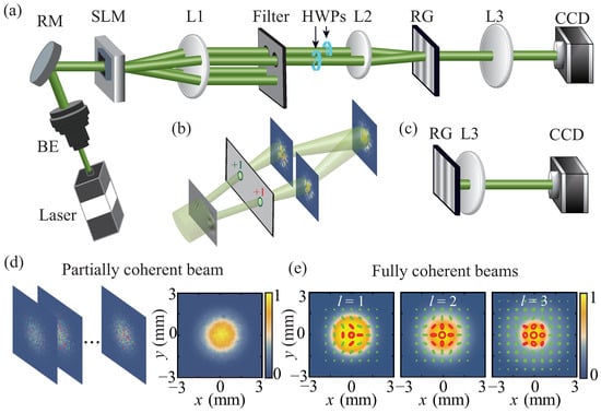
Figure 1.
(a) Experimental setup for synthesizing the FP beam and encoding it into the spatial coherence structure of a partially coherent beam. (b) Synthesis of vector mode by a spatial light modulator with its screen split into two halves. (c) Experimental setup for studying the focusing properties of the synthesized beams. (d) Simulation results of the instantaneous intensities and polarization states of the random field realizations, as well as the averaged intensity, for the synthesized partially coherent beam source with an FP polarization state of and encoded. (e) Simulation results of the intensities and polarization states for the synthesized fully coherent FP beams with and 3 ().
The diffracted light from the SLM then enters a common path interferometric system, which is composed of two thin lenses L1 and L2. The SLM is positioned in the input plane of the system, while a two-pinhole filter is located in the frequency plane (rear focal plane of L1) to selectively extract two diffraction orders. These beams are subsequently converted into x- and y-polarized states using half-wave plates (HWPs). In the output plane (rear focal plane of L2), a Ronchi grating (RG) is employed to superpose the two orthogonal modes into a single random vector mode []. By dynamically displaying the holograms on the SLM, the partially coherent beam source with an FP polarization state encoded in it can be synthesized immediately after the RG. The number of the holograms required for synthesizing the partially coherent beam depends on the spatial coherence area of the beam. As the spatial coherence area decreases, the necessary number of holograms increases. In our experiment, we utilize holograms to synthesize the partially coherent beam with low spatial coherence, which shows a good robustness property during propagation. The thin lens L3 in Figure 1a is used to image the beam source onto the CCD. The distances between the RG and L3, and between L3 and CCD, are both equal to , where is the focal distance of L3. As shown in Figure 1c, when L3 is placed immediately after RG, the focusing properties of the partially coherent beam can be studied.
To demonstrate the feasibility of the complex random-mode representation method, we first conduct the simulations based on Equations (17) and (18). Figure 1d shows the simulation results of the instantaneous intensities and polarization states of the random field realizations for the partially coherent beam in the source plane. The averaged intensity of the partially coherent beam with realizations is also shown in Figure 1d. The encoded FP polarization state has parameters and . In such a case, the vector quality factor of the FP beam is , and the synthesized partially coherent beam is unpolarized. It is noteworthy that the random modes are fully coherent and fully polarized despite the intensity and polarization state being spatially random. By adding these random modes in an incoherent manner, the resulting field becomes partially coherent and unpolarized. The simulation results in Figure 1d align well with our predictions. In Figure 1e, we display the simulation results of the intensities and polarization states for the fully coherent FP beams with different topological charges. For all three cases, the polarization states are located on the equators of the higher-order Poincaré spheres. It is clearly seen that the polarization states for the FP beams exhibit spatial nonuniformity.
5. Results and Discussion
In this section, we present and discuss the experimental results. In Figure 2, the experimental results of the measured local Stokes parameters, polarization states, and degrees of polarization for the FP polarization states with different polar angles are shown. The experimental results for the corresponding partially coherent beams in the source plane are also presented. For all three cases, the topological charges are equal to 1. The polarization state for the FP beam with polar angle , and is located in the northern part, on the equator, and in the southern part of the higher-order Poincaré sphere, respectively. The Stokes parameters for the partially coherent beam are measured with the standard method [].
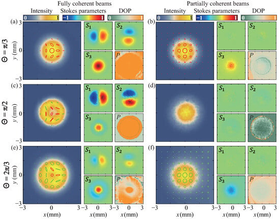
Figure 2.
Experimental results of the measured intensities, Stokes parameters, polarization states, and degrees of polarization for the synthesized fully coherent FP beams (left panels) and the corresponding partially coherent beam sources (right panels). In (a,b), and . In (c,d), and . In (e,f), and . The red ellipses denote the right-handed circular (or elliptical) polarization states, while the green ones denote the left-handed circular (or elliptical) polarization states.
When the polarization state is located in the northern part, we find in Figure 2a that more right-handed circular (or elliptical) polarization states are present in the FP beam with . The resulting partially coherent beam in the source plane is, therefore, partially polarized with the polarization state and the degree of polarization being uniform in the space [see Figure 2b]. When , we find for the FP beam. The corresponding partially coherent beam source is unpolarized as illustrated in Figure 2d. When the FP polarization state moves to the southern part of the higher-order Poincaré sphere (), we find that the beam predominantly exhibits left-handed circular (or elliptical) polarization states with . The corresponding partially coherent source becomes partially polarized again with spatially uniform polarization properties within the effective beam spot.
To examine whether the condition shown in Equation (14) holds, we present experimental results (depicted as blue dots) in Figure 3 for the variation of the local degree of polarization P for the partially coherent beam in the source plane with the polar angle of the encoded FP polarization state. The red solid curve in Figure 3 represents the theoretical result based on Equation (14). It is evident that the local degree of polarization of the synthesized partially coherent beam can be controlled by the polar angle of the FP polarization state. For the cases when and , the polarization states for the FP beams are located at the northern and southern poles, respectively. The FP beams, therefore, become uniformly polarized with the vector quality factor . The local degree of polarization for the corresponding partially coherent beams becomes 1. When , the vector quality factor for the FP beam and the local degree of polarization for the corresponding partially coherent beam becomes 0. For other values of , the local degrees of polarization for the partially coherent beams align well with the condition in Equation (14). Our experimental results are consistent with the theoretical predications.
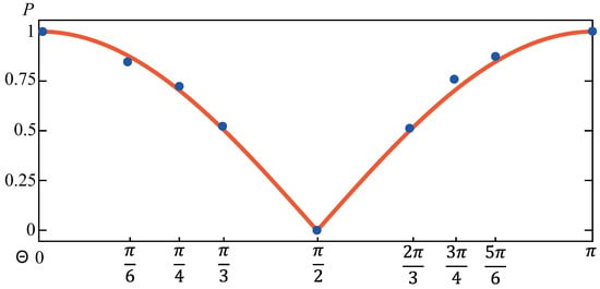
Figure 3.
The variation of the local degree of polarization P for the synthesized partially coherent beam source with the polar angle of the encoded FP polarization state. The blue dots denote the experimental results, while the red curve is calculated by Equation (14).
Next, we study the propagation properties for the fully coherent FP beams and for the partially coherent beams with FP polarization states encoded in the spatial coherence structures. Figure 4a–c present the experimental results for the Stokes parameters and polarization states of the focused fully coherent FP beam with and at various propagation distances. In the source plane (), we find that the fully coherent FP beam is well synthesized in the experiment with its polarization state being consistent with the simulation result shown in Figure 1e. Both the spatial distributions for and exhibit the two-petal shape, with mirroring the shape of through a 90-degree clockwise rotation. The spatial distribution of , on the other hand, displays rotational symmetry, featuring positive in the central area and negative in the surrounding regions. As the fully coherent FP beam propagates, its polarization state undergoes a counterclockwise rotation. Upon reaching the focal plane (), the polarization state rotates 90 degrees counterclockwise compared to its orientation in the source plane. This rotation is attributed to the vortex phase embedded in the left-handed circularly polarized mode [refer to in Equation (4)] of the FP polarization state. The asymmetry in vortex phase distributions within and contributes to the observable rotation. In contrast, if the vortex phases in and are symmetric (e.g., for a radially polarized beam), the rotation of the polarization state would not be visible during beam propagation. Figure 4d,e showcase experimental results for the focal-plane intensities and polarization states of FP beams with topological charges and . Notably, the observed rotation angle of the polarization state adheres to the condition .
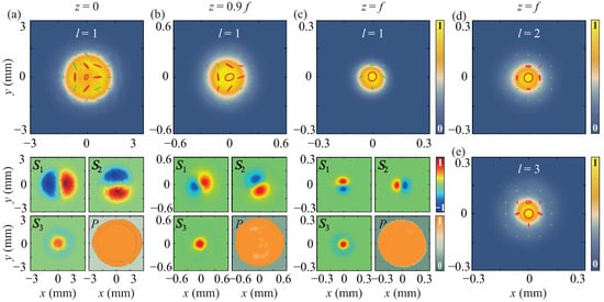
Figure 4.
Experimental results of the intensities, Stokes parameters, polarization states, and degrees of polarization for the focused fully coherent FP beam with and at (a) (source), (b) , and (c) (focal plane). (d,e) show the experimental results of the intensities and polarization states for the fully coherent FP beams in the focal plane with and .
In addition to the asymmetry vortex phases, the obstruction encountered by the fully FP beam during its propagation also influences its polarization distributions. In our experiment, we introduce a sector-shaped obstacle with an angle of and place it in the source plane to partially block the FP beam. Figure 5a shows the blocked FP beam with in the source plane, where both the intensity and polarization state of the beam are affected due to the obstacle. We can see that only the unobstructed part of the FP beam is retained. The experimental results depicting the distributions of the polarization information in the focal plane for the FP beams with different topological charges are presented in Figure 5b–d. As expected, the Stokes parameters (and, therefore, the polarization state) in the focal plane undergo distortion due to the obstacle placed in the source plane. These findings suggest that fully coherent FP beams are highly sensitive to disturbances in their propagation path. Even when the fully coherent FP beam is not completely blocked, the asymmetry in vortex phases within the beam induces rotation during its propagation.
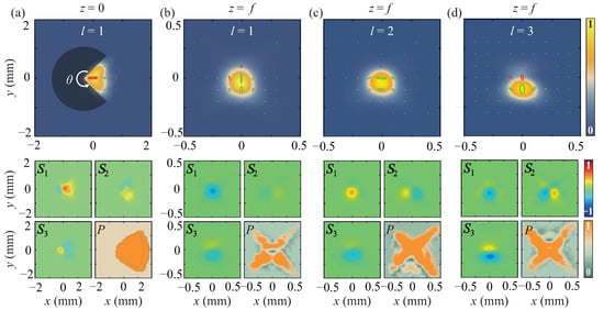
Figure 5.
Experimental results of the intensities, Stokes parameters, polarization states, and degrees of polarization for the fully coherent FP beam ( and ) blocked by a sector-shaped obstacle with an angle of at (a) and (b) . (c,d) show the experimental results for the FP beams with and in the focal plane. The beams are blocked by the same obstacle shown in (a,b).
We now turn to discuss the synthesis of a robust FP polarization state through the spatial coherence engineering of the partially coherent beam. Figure 6a shows the average intensity, Stokes parameters, and local degree of polarization of the synthesized partially coherent beam in the source plane. The partially coherent beam source is created with 1000 complex random modes, and with the FP polarization state of and encoded in it. As we have predicted, when the encoded beam has a vector quality factor , the synthesized partially coherent beam in the source plane is locally unpolarized. The experimental results shown in Figure 6a align with our predictions. Due to the modulation of the vectorial spatial coherence structure, the encoded FP polarization state reappears during the propagation of the partially coherent beam. This is confirmed in our experimental results presented in Figure 6b,c. Comparing the spatial distributions of the Stokes parameters shown in Figure 6b,c with those for the encoded FP polarization state shown in Figure 4a, we find that, indeed, the polarization state appears in the beam again. Notably, unlike the polarization state of a fully coherent FP beam, which undergoes rotation during propagation, the partially coherent beam maintains a consistent spatial distribution of the polarization state at various propagation distances. This consistency arises from the fact that the polarization state is locked in the spatial coherence structure of the partially coherent beam source. Furthermore, when comparing the degree of polarization in Figure 6a–c, it is observed that the beam becomes more polarized with an increase in propagation distance. In the focal plane, we find that the beam is nearly fully polarized within the effective beam region. By modulating the dynamic holograms loaded in the SLM [achieved through modulating in Equation (18)], FP polarization states with different topological charges can be encoded into the partially coherent beam. Figure 6d,e show the experimental results for the focal-plane intensities and polarization states of the partially coherent beams with and . Comparing Figure 6d,e with Figure 1e, we find that the encoded higher-order FP polarization states are recovered in the focal plane.
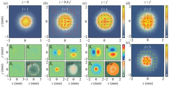
Figure 6.
Experimental results of the intensities, Stokes parameters, polarization states, and degrees of polarization for the focused partially coherent beam, with FP polarization state of and encoded, at (a) (source), (b) , and (c) (focal plane). (d,e) show the experimental results of the intensities and polarization states for the partially coherent beams in the focal plane with the FP polarization states of and encoded.
The robustness of the partially coherent beam is assessed by introducing the same sector-shaped obstacle used in Figure 5 into the source plane of the partially coherent beam. We note that only the initial intensity and polarization are affected by the obstacle, as depicted in Figure 7a. The second-order spatial coherence structure of the partially coherent source remains unaffected. Since the FP polarization state is encoded only in the spatial coherence structure, the focal-plane polarization state can, therefore, be well recovered. Figure 7b–d present the recovered polarization distributions for the partially coherent beams with , , and that are obstructed by the sector-shaped obstacle. We find that the recovered polarization states in the focal plane are consistent with the encoded FP polarization states and are nearly unaffected by the obstacle placed in the source plane. These experimental results are in agreement with the theoretical predication outlined in Equation (15). When the spatial coherence area of the beam source is significantly smaller than the opening area of the obstacle, the recovered focal-plane polarization state is solely determined by the encoded state in the partially coherent beam source.
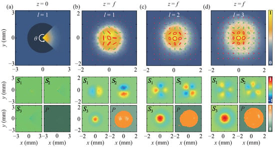
Figure 7.
Experimental results of the intensities, Stokes parameters, polarization states, and degrees of polarization for the partially coherent beam (with FP polarization state of and encoded) blocked by a sector-shaped obstacle with an angle of at (a) and (b) . (c,d) show the experimental results for the partially coherent beams with and in the focal plane. The beam sources are blocked by the same obstacle shown in (a,b).
The quality of the focal-plane FP polarization state is clearly related to the spatial coherence of the engineered partially coherent beam source. In our experiment, we investigated the relationship between the source’s spatial coherence and the quality of the focal-plane polarization by manipulating the spatial coherence of the beam source and adjusting the size of the obstacle. In Figure 8, we examine two scenarios with lower and higher spatial coherence compared to Figure 6 and Figure 7. The sector-shaped obstacles have angles of and , representing smaller and larger obstacles, respectively. The spatial coherence of the partially coherent beam is controlled by varying the beam waist of in the experiment. Figure 8a illustrates the spatial distributions of polarization information in the case of a lower spatial coherence and a smaller obstacle, demonstrating the attainment of a high-quality FP polarization state in the received plane. In contrast, Figure 8b presents spatial distributions for a higher spatial coherence and a smaller obstacle, revealing slightly distorted patterns in intensity and polarization state, lower contrast in the Stokes parameters, and a reduced degree of polarization. This emphasizes that a higher spatial coherence results in the lower quality and less robustness of the focal-plane FP polarization state. Subsequently, we increased the angle of the sector-shaped obstacle. As shown in Figure 8c, due to the smaller spatial coherence, the high-quality FP polarization state can still maintain in the focal plane. However, in the case of the higher spatial coherence, the quality of the FP polarization state in the focal plane is obviously abnormal as shown in Figure 8d. A comparison of the degrees of polarization between Figure 8b,d reveals that with the increase in obstacle area, the beam in the focal plane becomes less polarized.
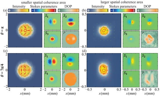
Figure 8.
Experimental results of the focal-plane intensities, Stokes parameters, polarization states, and degrees of polarization for the partially coherent beams with FP polarization state of and encoded. In (a,c), the spatial coherence area of the beam source is smaller than that in Figure 6 and Figure 7, while in (b,d), the spatial coherence area of the source is larger than that in Figure 6 and Figure 7. In (a,b), the beam sources are blocked by the sector-shaped obstacle with an angle of , while in (c,d), the beam sources are blocked by the sector-shaped obstacle with an angle of .
6. Conclusions
In summary, we introduced a novel approach to synthesize robust full Poincaré (FP) polarization states through the spatial coherence engineering of a partially coherent light beam. The experimental demonstration illustrated the effective encoding of FP polarization states into the second-order spatial coherence structure of the partially coherent beam source using the complex random-mode representation method. Throughout the encoding process, we found that although the vectorness of the beam remained constant, the vector nature transitioned from the polarization state of the FP beam to the spatial coherence structure of the partially coherent source. Remarkably, during the propagation of the engineered partially coherent beam, the vectorness reverted to the polarization state, leading to the reemergence of the encoded FP polarization state in the beam. Our findings indicate that, with a sufficiently small spatial coherence area for the partially coherent source, a high-quality FP polarization state with a high local degree of polarization could be synthesized in the focal plane of the focused partially coherent beam. Notably, the high quality and high degree of polarization of the FP polarization state persisted even when the engineered partially coherent beam source was significantly obstructed by an obstacle. These results present a novel method for synthesizing robust FP polarization states, with potential applications in optical imaging and optical trapping through complex media.
Author Contributions
Conceptualization, Y.C. (Yahong Chen); methodology, Y.C. (Yahong Chen); software, R.Z., M.Z. and Z.D.; validation, R.Z., M.Z., Z.D. and Y.C. (Yahong Chen); formal analysis, R.Z., M.Z., Z.D., F.W., Y.C. (Yangjian Cai) and Y.C. (Yahong Chen); investigation, R.Z., M.Z., Z.D., F.W., Y.C. (Yangjian Cai) and Y.C. (Yahong Chen); writing—original draft preparation, Z.D. and Y.C. (Yahong Chen); writing—review and editing, Y.C. (Yahong Chen); visualization, R.Z., M.Z., Z.D. and Y.C. (Yahong Chen); supervision, Y.C. (Yahong Chen); project administration, Y.C. (Yahong Chen); funding acquisition, F.W., Y.C. (Yangjian Cai) and Y.C. (Yahong Chen). All authors have read and agreed to the published version of the manuscript.
Funding
This research was funded by the National Key Research and Development Program of China (Grants No. 2022YFA1404800 and No. 2019YFA0705000), the National Natural Science Foundation of China (Grants No. 11974218, No. 12192254, No. 12274310, and No. 92250304), the Postgraduate Research & Practice Innovation Program of Jiangsu Province (Grant No. KYCX23_3227), Hui-Chun Chin and Tsung-Dao Lee Chinese Undergraduate Research Endowment (CURE), and the Undergraduate Training Program for Innovation and Entrepreneurship, Soochow University (Grant No. 202210285128Y).
Institutional Review Board Statement
Not applicable.
Informed Consent Statement
Not applicable.
Data Availability Statement
Data underlying the results presented in this paper are not publicly available at this time but may be obtained from the authors upon reasonable request.
Conflicts of Interest
The authors declare no conflicts of interest.
Abbreviations
The following abbreviations are used in this manuscript:
| FP | Full Poincaré |
| BE | Beam expander |
| RM | Reflecting mirror |
| SLM | Spatial light modulator |
| L | Lens |
| HWP | Half-wave plate |
| RG | Ronchi grating |
References
- Zhan, Q. Cylindrical vector beams: From mathematical concepts to applications. Adv. Opt. Photon. 2009, 1, 1–57. [Google Scholar] [CrossRef]
- Rosales-Guzmán, C.; Ndagano, B.; Forbes, A. A review of complex vector light fields and their applications. J. Opt. 2018, 20, 123001. [Google Scholar] [CrossRef]
- Bouchard, F.; Larocque, H.; Yao, A.M.; Travis, C.; De Leon, I.; Rubano, A.; Karimi, E.; Oppo, G.-L.; Boyd, R.W. Polarization Shaping for Control of Nonlinear Propagation. Phys. Rev. Lett. 2016, 117, 233903. [Google Scholar] [CrossRef] [PubMed]
- Maucher, F.; Skupin, S.; Gardiner, S.A.; Hughes, I.G. Creating Complex Optical Longitudinal Polarization Structures. Phys. Rev. Lett. 2018, 120, 163903. [Google Scholar] [CrossRef] [PubMed]
- Fu, S.; Guo, C.; Liu, G.; Li, Y.; Yin, H.; Li, Z.; Chen, Z. Spin-Orbit Optical Hall Effect. Phys. Rev. Lett. 2019, 123, 243904. [Google Scholar] [CrossRef] [PubMed]
- Giordani, T.; Suprano, A.; Polino, E.; Acanfora, F.; Innocenti, L.; Ferraro, A.; Paternostro, M.; Spagnolo, N.; Sciarrino, F. Machine Learning-Based Classification of Vector Vortex Beams. Phys. Rev. Lett. 2020, 124, 160401. [Google Scholar] [CrossRef] [PubMed]
- Zhu, Z.; Janasik, M.; Fyffe, A.; Hay, D.; Zhou, Y.; Kantor, B.; Winder, T.; Boyd, R.W.; Leuchs, G.; Shi, Z. Compensation-free high-dimensional free-space optical communication using turbulence-resilient vector beams. Nat. Commun. 2021, 12, 1666. [Google Scholar] [CrossRef] [PubMed]
- Ye, L.; Yang, L.; Zheng, X.; Mukamel, S. Enhancing Circular Dichroism Signals with Vector Beams. Phys. Rev. Lett. 2021, 126, 123001. [Google Scholar] [CrossRef]
- Black, A.N.; Choudhary, S.; Arroyo-Rivera, E.S.; Woodworth, H.; Boyd, R.W. Suppression of Nonlinear Optical Rogue Wave Formation Using Polarization-Structured Beams. Phys. Rev. Lett. 2022, 129, 133902. [Google Scholar] [CrossRef]
- Ishihara, J.; Mori, T.; Suzuki, T.; Sato, S.; Morita, K.; Kohda, M.; Ohno, Y.; Miyajima, K. Imprinting Spatial Helicity Structure of Vector Vortex Beam on Spin Texture in Semiconductors. Phys. Rev. Lett. 2023, 130, 126701. [Google Scholar] [CrossRef]
- Beckley, A.M.; Brown, T.G.; Alonso, M.A. Full Poincaré beams. Opt. Express 2010, 18, 10777–10785. [Google Scholar] [CrossRef]
- Han, W.; Cheng, W.; Zhan, Q. Flattop focusing with full Poincaré beams under low numerical aperture illumination. Opt. Lett. 2011, 36, 1605–1607. [Google Scholar] [CrossRef]
- Wang, L.G. Optical forces on submicron particles induced by full Poincaré beams. Opt. Express 2012, 20, 20814–20826. [Google Scholar] [CrossRef] [PubMed]
- de Sande, J.C.G.; Santarsiero, M.; Piquero, G. Spirally polarized beams for polarimetry measurements of deterministic and homogeneous samples. Opt. Lasers Eng. 2017, 91, 97–105. [Google Scholar] [CrossRef]
- Suárez-Bermejo, J.C.; de Sande, J.C.G.; Santarsiero, M.; Piquero, G. Mueller matrix polarimetry using full Poincaré beams. Opt. Lasers Eng. 2019, 122, 134–141. [Google Scholar] [CrossRef]
- Gu, Y.; Korotkova, O.; Gbur, G. Scintillation of nonuniformly polarized beams in atmospheric turbulence. Opt. Lett. 2009, 34, 2261–2263. [Google Scholar] [CrossRef] [PubMed]
- Ling, X.; Yi, X.; Dai, Z.; Wang, Y.; Chen, L. Characterization and manipulation of full Poincaré beams on the hybrid Poincaré sphere. J. Opt. Soc. Am. B 2016, 33, 2172–2176. [Google Scholar] [CrossRef]
- Galvez, E.J.; Khadka, S.; Schubert, W.H.; Nomoto, S. Poincaré beam patterns produced by nonseparable superpositions of Laguerre–Gauss and polarization modes of light. Appl. Opt. 2012, 51, 2925–2934. [Google Scholar] [CrossRef] [PubMed]
- Cardano, F.; Karimi, E.; Marrucci, L.; de Lisio, C.; Santamato, E. Generation and dynamics of optical beams with polarization singularities. Opt. Express 2013, 21, 8815–8820. [Google Scholar] [CrossRef] [PubMed]
- Bauer, T.; Banzer, P.; Karimi, E.; Orlov, S.; Rubano, A.; Marrucci, L.; Santamato, E.; Boyd, R.W.; Leuchs, G. Observation of optical polarization Möbius strips. Science 2015, 347, 964–966. [Google Scholar] [CrossRef]
- Piquero, G.; Martínez-Herrero, R.; De Sande, J.C.G.; Santarsiero, M. Synthesis and characterization of non-uniformly totally polarized light beams: Tutorial. J. Opt. Soc. Am. A 2020, 37, 591–605. [Google Scholar] [CrossRef]
- Zhang, L.; Qiu, X.; Li, F.; Liu, H.; Chen, X.; Chen, L. Second harmonic generation with full Poincaré beams. Optics Express 2018, 26, 11678–11684. [Google Scholar] [CrossRef]
- Black, A.N.; Boyd, R.W. Generation of volumetrically full Poincaré beams. J. Opt. Soc. Am. A 2022, 39, C161–C166. [Google Scholar] [CrossRef]
- Kumar, S.; Saripalli, R.K.; Ghosh, A.; Buono, W.T.; Forbes, A.; Samanta, G.K. Controlling the coverage of full poincaré beams through second-harmonic generation. Phys. Rev. Applied 2023, 19, 034082. [Google Scholar] [CrossRef]
- Piquero, G.; Monroy, L.; Santarsiero, M.; Alonzo, M.; de Sande, J.C.G. Synthesis of full Poincaré beams by means of uniaxial crystals. J. Opt. 2018, 20, 065602. [Google Scholar] [CrossRef]
- Vyas, S.; Kozawa, Y.; Sato, S. Self-healing of tightly focused scalar and vector Bessel–Gauss beams at the focal plane. J. Opt. Soc. Am. A 2011, 28, 837–843. [Google Scholar] [CrossRef]
- Wu, G.; Wang, F.; Cai, Y. Generation and self-healing of a radially polarized Bessel–Gauss beam. Phys. Rev. A 2014, 89, 043807. [Google Scholar] [CrossRef]
- Cheng, W.; Haus, J.W.; Zhan, Q. Propagation of vector vortex beams through a turbulent atmosphere. Opt. Express 2009, 17, 17829–17836. [Google Scholar] [CrossRef]
- Cox, M.A.; Rosales-Guzmán, C.; Lavery, M.P.J.; Versfeld, D.J.; Forbes, A. On the resilience of scalar and vector vortex modes in turbulence. Opt. Express 2016, 24, 18105–18113. [Google Scholar] [CrossRef] [PubMed]
- Goodman, J.W. Speckle Phenomena in Optics: Theory and Applications; Roberts and Company: Greenwood Village, CO, USA, 2007. [Google Scholar]
- Yu, J.; Zhu, X.; Wang, F.; Chen, Y.; Cai, Y. Research progress on manipulating spatial coherence structure of light beam and its applications. Prog. Quantum Electron. 2023, 91, 100486. [Google Scholar] [CrossRef]
- Peng, D.; Huang, Z.; Liu, Y.; Chen, Y.; Wang, F.; Ponomarenko, S.A.; Cai, Y. Optical coherence encryption with structured random light. PhotoniX 2021, 2, 6. [Google Scholar] [CrossRef] [PubMed]
- Chen, Y.; Wang, F.; Cai, Y. Partially coherent light beam shaping via complex spatial coherence structure engineering. Adv. Phys. X 2022, 7, 2009742. [Google Scholar] [CrossRef]
- Friberg, A.T.; Setälä, T. Electromagnetic theory of optical coherence [Invited]. J. Opt. Soc. Am. A 2016, 33, 2431–2442. [Google Scholar] [CrossRef] [PubMed]
- McLaren, M.; Konrad, T.; Forbes, A. Measuring the nonseparability of vector vortex beams. Phys. Rev. A 2015, 92, 023833. [Google Scholar] [CrossRef]
- Nape, I.; Singh, K.; Klug, A.; Buono, W.; Rosales-Guzman, C.; McWilliam, A.; Franke-Arnold, S.; Kritzinger, A.; Forbes, P.; Dudley, A.; et al. Revealing the invariance of vectorial structured light in complex media. Nat. Photonics 2022, 16, 538–546. [Google Scholar] [CrossRef]
- Dong, Z.; Yuan, B.; Liu, Y.; Wang, F.; Cai, Y.; Chen, Y. Stokes scintillations for vector beams in turbulence. Chin. Opt. Lett. 2023, 21, 100101. [Google Scholar] [CrossRef]
- Mandel, L.; Wolf, E. Optical Coherence and Quantum Optics; Cambridge University Press: Cambridge, UK, 1995. [Google Scholar]
- Dong, Z.; Chen, Y.; Wang, F.; Cai, Y.; Friberg, A.T.; Setälä, T. Encoding higher-order polarization states into robust partially coherent optical beams. Phys. Rev. Appl. 2022, 18, 034036. [Google Scholar] [CrossRef]
- Liu, S.; Qi, S.; Zhang, Y.; Li, P.; Wu, D.; Han, L.; Zhao, J. Highly efficient generation of arbitrary vector beams with tunable polarization, phase, and amplitude. Photon. Res. 2018, 6, 228–233. [Google Scholar] [CrossRef]
- Hyde IV, M.W.; Basu, S.; Voelz, D.G.; Xiao, X. Experimentally generating any desired partially coherent Schell-model source using phase-only control. J. Appl. Phys. 2015, 118, 093102. [Google Scholar] [CrossRef]
- Hyde IV, M.W. Stochastic complex transmittance screens for synthesizing general partially coherent sources. J. Opt. Soc. Am. A 2020, 37, 257–264. [Google Scholar] [CrossRef]
- Wang, X.-L.; Ding, J.; Ni, W.-J.; Guo, C.-S.; Wang, H.-T. Generation of arbitrary vector beams with a spatial light modulator and a common path interferometric arrangement. Opt. Lett. 2007, 32, 3549–3551. [Google Scholar] [CrossRef] [PubMed]
- Meemon, P.; Salem, M.; Lee, K.-S.; Chopra, M.; Rolland, J.P. Determination of the coherency matrix of a broadband stochastic electromagnetic light beam. J. Mod. Opt. 2008, 55, 2765–2776. [Google Scholar] [CrossRef]
Disclaimer/Publisher’s Note: The statements, opinions and data contained in all publications are solely those of the individual author(s) and contributor(s) and not of MDPI and/or the editor(s). MDPI and/or the editor(s) disclaim responsibility for any injury to people or property resulting from any ideas, methods, instructions or products referred to in the content. |
© 2024 by the authors. Licensee MDPI, Basel, Switzerland. This article is an open access article distributed under the terms and conditions of the Creative Commons Attribution (CC BY) license (https://creativecommons.org/licenses/by/4.0/).