Article

Designing an Optical Router Based on a Multimode-Interference Silicon-On-Insulator Coupler with Tunable Power Transmittance

Department of Physics, School of Science and Engineering, The American University in Cairo, Cairo 11835, Egypt
*
Author to whom correspondence should be addressed.
Photonics 2024, 11(3), 221; https://doi.org/10.3390/photonics11030221
Submission received: 22 December 2023 / Revised: 8 February 2024 / Accepted: 19 February 2024 / Published: 29 February 2024
(This article belongs to the Special Issue Integrated Waveguide-Based Photonic Devices)

Abstract

:
The demand on fast and high-bandwidth data transmission is in continuous increase. These demands are highly dependent on optical signal manipulation, including switching, modulation, and routing. We demonstrate a two-port silicon optical router based on the multimode interferometer (MMI) configuration. The same MMI structure was used for both inward and backward waveguiding to reduce the total length of the device. A phase shifter consisting of two ring-like waveguides made of silicon p-n junctions was used to introduce the phase shift needed for optical routing upon voltage application. Two designs for the MMI optical router were studied: Firstly, a conventional MMI with a crosstalk ratio of 15.1 dB was investigated. Finally, an angled MMI reaching a crosstalk ratio of 18.2 dB at a wavelength of 1.55 μm was investigated.

1. Introduction

Optical routing and switching are essential functions in optical networking systems. The main applications of optical routing are manifested in the wavelength-division multiplexing and demultiplexing in optical networks. The growing demand for ultrafast optical communication devices backed by the increased requirements for higher internet bandwidths is creating the need for faster and lower-power-consumption routing mechanisms [1]. Thereby, extensive research to develop high-performance optical switching and routing is of increasing interest. These requirements cannot be fulfilled without the all-optical processing of data traffic, since optical–electronic–optical signal conversion presents as a limiting parameter to the network switching speed and consequently to the offered bandwidth. As for the data transfer medium, optical fibers serve as a high-speed optical medium or waveguide for data transmission, while data processing and traffic switching are associated with the optical nodes linking different optical network components.
Integrated optical components and photonic circuits are the dominant implemented technologies used in the design of optical nodes [2]. Optical routers and multiplexers show high potential for transferring data between optical nodes with speeds matching the high-speed data transmission through optical fibers. Optical routers and splitters [3] based on integrated optical devices are usually based on photonic components such as multimode interferometers (MMIs) [4,5,6], Mach Zender interferometers [7,8], directional couplers [9,10], and ring resonators [11,12].
In particular, MMIs have shown their success in different applications due to their ability to control and manipulate different wavelengths/frequencies of light, while their fabrication and performance can be readily controlled [13]. Thus, MMIs have been incorporated in the design and structure of photonic devices for different applications such as power dividers and combiners [14], biosensors [15,16], multiplexers [17], optical switches [18], thermo-optic switches [19], and wavelength filters [20]. Moreover, angled MMI structures with improved coupling ratios and higher fabrication tolerances [21] have been used for gas sensing [22] and multiplexing [23] applications.
State-of-the-art optical multiplexers that used arrayed waveguide grating-based MMIs [24] showed crosstalk values of 12.7 dB, and an insertion loss of 1 dB. Improved crosstalk values of 22 dB were reported for Bragg reflector-based multiplexers [25], with an insertion loss of 1.65 dB. Moreover, a crosstalk of 23.35 dB with an insertion loss of 0.82 was achieved using a multimode wavelength demultiplexer [26], all at the 1.55 μm wavelength.
Hereby, we demonstrate a low-crosstalk and low-insertion-loss optical router device based on the MMI properties of self-imaging, in addition to a phase shifter connected to the MMI to form a feedback loop. The MMI section of the device acts as the forward as well as the backward waveguide for the multimode signal. Moreover, the SOI optical router is fully CMOS compatible. Firstly, we present a conventional MMI design with a crosstalk value of 15.1 dB. Furthermore, we present a more-advanced angled MMI design with a lower crosstalk that reaches 18.2 dB.

2. Device Structure

The MMI router consists of three main parts: firstly, the input and output ports; secondly, the MMI, supporting multimode propagation to deliver the signal to the third part of the device, which is the feedback loop. A Y-junction component was used to split the electromagnetic signal into the two paths of the feedback loop. The basic concept in our device operation is to use the same MMI region for both the forward and backward propagation directions of the electromagnetic wave to reduce the total device length. Meanwhile, the routing mechanism is based on phase shifting, introduced by means of applying voltage on the silicon p-n junction region of the feedback loop.
Two different MMI-based routers were designed and simulated at the 1.55 μm wavelength. The first design (Figure 1) uses conventional MMI, which is feasible to fabricate with low fabrication tolerance, while the second design is an angled MMI (AMMI), characterized by its lower insertion loss and less crosstalk, as will be discussed further. The insets to Figure 1 show the input tapered port and the magnified Y-junction with its corrugated boundaries, optimized to minimize the insertion losses. The region in the blue-dotted box in the upper ring contains the part of the ring that introduces the phase difference between the two rings using the applied voltage.

3. Simulation Methods

The router device was designed and its parameters and dimensions were studied using 3D FDTD computational methods through a commercially available 3D electromagnetic simulator [27]. In addition, a particle-swarm algorithm was implemented for studying and optimizing the Y-junction splitting ratio [28]. The input tapered Port A was excited using a transverse electric (TE) sign centered at the 1.55 mm wavelength. A mesh size of 50 nm was suitable to provide high-resolution results with reasonable computational time and memory requirements. Sixteen perfectly matched layers were used for the boundary condition of our simulation window to ensure no reflections to our simulation region. The refractive index profiles of the Si rib waveguide and SiO2 cladding oxide were adopted from [29].

4. Results and Discussion

4.1. The Conventional MMI Design

Signal propagation and higher-mode excitation are strongly dependent on the MMI waveguide length. The length of the MMI was optimized to ensure conditions for both the symmetric single self-image (forward) and the paired self-image (backward). While the optical signal is propagating in the forward direction, it encounters the MMI as a 1 × 1 MMI with a length of 2 LFS (forward single-image length). However, in the backward direction, the optical signal encounters the MMI as a 2 × 2 MMI with a length of 3 LBP (backward paired-image length). The MMI region has a width of WMMI = 6 μm, and a length of LMMI = 127.5 μm. We reported initial work on the theory of the proposed device in [30].
The MMI waveguide was symmetrically excited in the forward direction (Port A), giving a single symmetrical image at the output port (Port B). This signal was then split into two equal halves using a Y-junction. Each half was guided in a single-mode ring-like waveguide to be coupled to the MMI as a feedback source at the paired excitation positions at y = ± WMMI/6 (Ports 3 and 4). According to the phase shift between the two rings, the signal can be routed to one of the output ports (Port 1 or Port 2), as shown in Figure 2 (Binary Router), or can be divided between the two output ports based on the introduced phase shift not equal to −90° or 90° (Tunable Power-Transmittance Coupler).
For the general case, we can study the variation in transmitted power between the two ports as a function of the phase shift between the two rings. Simulation sweeps were performed using varFDTD methods to study the effect of the phase shift on the output power for both ports. The simulation results show that the transmitted power of the ports changed in an alternating cos(2φ) [2] pattern, where φ is the phase difference between the two feedback sources. The transmitted power switched to Port 1 when the phase shift between the two rings was around −90°, and then switched back to Port 2 when the phase shift was around 90°. The results show the switch between the two outputs as the phase shift changes between the upper and the bottom rings, with 15.14 dB crosstalk in the monitored value of the output Port 1.

4.1.1. The Input/Output Taper and MMI Length/Width Dimensions’ Optimization

Linear tapers were used at both the input and output ports to minimize the MMI loss and were studied using a commercial waveguide simulator based on the Finite-Difference Eigenmode, “FDE” [31]. It was found that the power losses after passing through the MMI core decreased as we increased the width of the input taper. The taper width at the base of the MMI is about 1.1 μm; this resulted in an optimization of taper transmission with its width. The taper width matches the MMI width without overlapping with the other adjacent ports. The highest measured transmission was found at a length of 127.5 μm and a width of 6.03 μm.

4.1.2. Losses and Crosstalk Variation with Wavelength

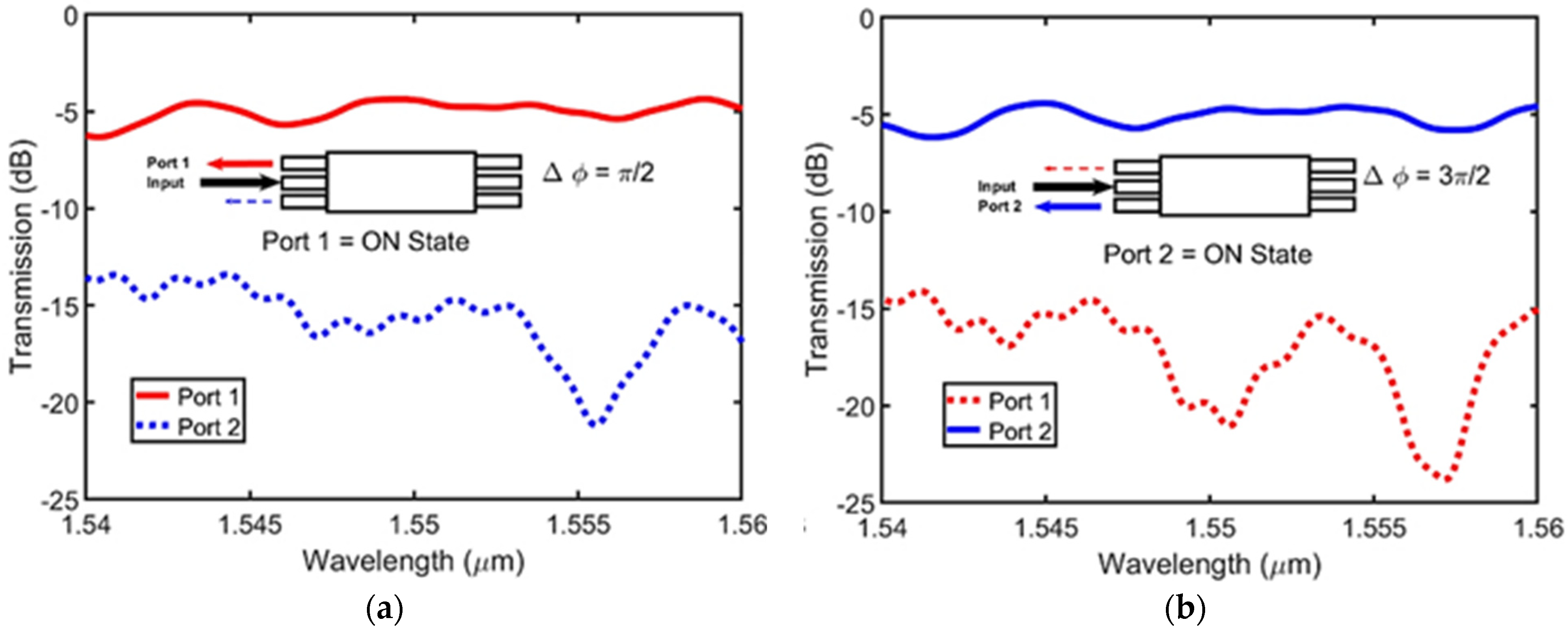
The losses in the whole structure were studied by placing monitors at different positions. We conducted a power budget analysis of the structure, where the power was traced from the entrance at Port A until it split back to Ports 1 and 2. The results show that the losses in the Y-junction and the rings are about 0.034 and 0.03 in ratio, respectively. Figure 3 shows the variation in the transmission at Port 1 and Port 2 outputs with different spans of wavelength.
The 3D distribution of the |E| is shown in Figure 4. The structure design is dispersive, and the power output value depends on the operating wavelength.

4.2. The Angled MMI Design

The coherence of the tapered waveguide was used to change the spot size and reduce the optical losses, as shown in Figure 5. The width limitation in the structure forces the tapered base width not to exceed 1.1 µm. Increasing the tapered waveguide width to a suitable width would achieve high coupling efficiency in the cross-section boundary, and as a result, reduce the losses in the MMI [32]. We can achieve about 95% of the MMI output power by setting the ratio between the tapered base width and the MMI width (Wt/WMMI) to above 0.35 [33].
To improve the performance of the design with respect to the crosstalk between the two ports and to avoid issues due to space limitation in our structure, we replaced the paired excitation ports with angled ports and increased the tapers’ width for the inputs and outputs to Wt = 2.1 µm, while the length of the taper was Lt = 25 µm. The angle between the ports and the MMI at the input was optimized at an angle of 80°, as shown in Figure 5, with the MMI optimized length being 127.1 µm (decreased length compared to conventional MMI design). The device performance was enhanced significantly, as shown in Figure 6.

The Paired Excitation of the Structure

The proposed MMI structure can be used as a modulator when excited by one of the angled ports. Paired excitation of the MMI waveguide structure (Port 2) in the forward direction gives two paired images at the output ports (Port 3 and Port 4) with a phase difference equal to 90°.
Each one of these two signals are then guided in a single-mode ring-like waveguide and recombined using a Y-junction. The resulting signal in Port B is coupled to the MMI as a feedback source in a symmetrical excitation. According to the phase shift between the two rings, the signal can be modulated at the output port (Port A) based on the introduced phase shift equal to 90° or −90°, as shown in Figure 7a,b.
For practical applications, phase shifters are used to cause the routing. Different types of modulators can be used to cause the phase shift: one example is an optoelectronic material that can be placed in the silicon waveguide, where its refractive index changes with the applied voltage. A silicon-on-insulator free-carrier injection modulator is another type of modulator that would be more effective [34]. This modulator can use a pn-diode structure, as shown in Figure 8a, which is positioned around an optical rib waveguide; the applied voltage causes a change in the depletion region width, which causes a change in the effective refractive index, resulting in a phase shift. A three-radian phase shift was achieved by applying a voltage equal to 7 volts for the 3.3 mm device. In simulations, the phase shift is caused by changing the excess length of one ring based on the phase change simulation results of the pn-diode waveguides.
The routing is based on the carrier depletion effect [34] created in the feedback loop, which is built of a p-n Si-diode phase shifter [35], as shown in Figure 9. The p-n Si-junction waveguide has a width of 500 nm and a thickness of 220 nm, with n and p doping levels of 1.5 × 1017 cm−3 and 2.5 × 1017 cm−3, respectively.
Applying a reverse voltage of 6 V across the pn-junction perturbs the spatial carrier charge distribution, such that electrons and holes are drawn by the drain and source, respectively, resulting in a widening of the depletion region, as observed in Figure 8; this is calculated using a 3D charge transport simulator [36] utilizing the model in [37], which explains the effect of changes in doping concentrations/the spatial carrier distribution on the refractive index.
This change in the carrier distribution within the Si waveguide alters the modal effective index and loss, as shown in Figure 10, calculated using a waveguide simulator. The change in the effective index increases with the applied reverse voltage as Δ n e f f = n e f f V n e f f 0 , where n e f f V is the effective index at a V applied voltage, while n e f f 0 is the effective index at 0 applied voltage. Moreover, as the reverse voltage increases, carriers are drawn out of the Si waveguide, resulting in a fewer number of free carriers to interact with the Si effective mode, which lowers the modal losses of the waveguide. When the reverse voltage is applied to only one of the feedback loops, there will be a phase difference between the inputs at Ports 3 and 4. This phase difference is related to the effective index change by
Δ φ = β l = 2 π λ n e f f l
where β is the effective propagation constant, λ is the wavelength, and l is the length of the feedback loop segment where the reverse voltage is applied.
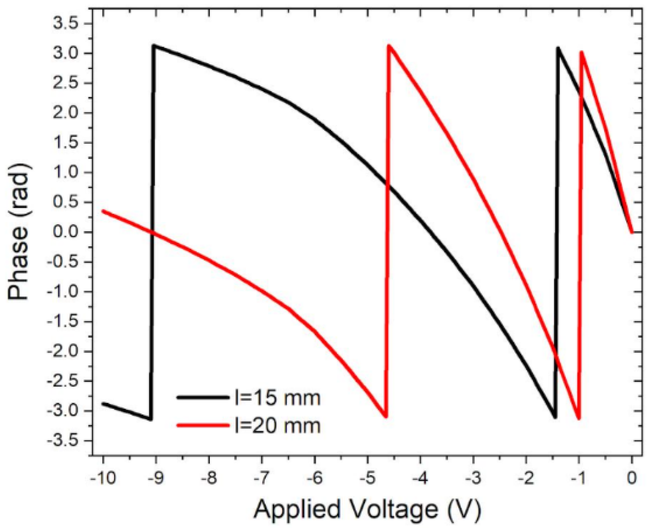
The phase change of the 2 mm phase shifter waveguide with the applied voltage was calculated using a waveguide simulator [31]. As can be observed from Figure 11, the 180° phase shift is achieved for a reverse applied voltage around −1 V, which results in the figure of merit Vπ lπ = 0.017 V.m. Nevertheless, it is worth mentioning that in the normal situation without applying voltage on the upper ring structure, there is a π/2 phase shift between the two rings.
Table 1 shows state-of-the-art MMI routers’ performances as compared to our work. Future work can include the fabrication of the device as well as studying the fabrication tolerance effects on the performance of our modulator. Moreover, exploring nano-materials exhibiting nonlinear optical effects [38], subwavelength structures [39], and phase-change materials [40] can result in improved optical-switching performance. Other alternatives may include using loop-terminated interferometers to improve the interaction of the optical field with the changing-phase material region [41].

5. Conclusions

Two integrated SOI-based optical router designs were demonstrated and analyzed using conventional MMI and angled MMI. Optical power in the MMI different ports was controlled by changing the phase using an optical shifter. The proposed concept is simple and can be utilized for routing, switching, and fast modulation with minimum changes. Phase-shift effects between the two feedback sources on the transmitted power of the output ports were studied using the varFDTD simulation method. Routing with a crosstalk between the ports of 15.14 dB was achieved for the compact conventional MMI, while for the angled MMI design, 18.2 dB of crosstalk was achieved. Measurements were taken at the 1.55 μm telecom wavelength.

Author Contributions

M.A.S. proposed the idea and supervised the project; D.S.A. and S.M.S. conducted the simulation and the formal analyses; M.A.O. helped with writing the draft. All authors have read and agreed to the published version of the manuscript.

Funding

This research was funded by the Physics Department of the American University in Cairo (AUC), Cairo, Egypt.

Data Availability Statement

The raw data supporting the conclusions of this article will be made available by the authors on request.

Acknowledgments

We acknowledge the support of the American University in Cairo (AUC).

Conflicts of Interest

The authors declare no conflicts of interest.

References

  1. Xu, Y.; Tian, Z.; Meng, X.; Chai, Z. Methods and applications of on-chip beam splitting: A review. Front. Phys. 2022, 10, 985208. [Google Scholar] [CrossRef]
  2. Okamoto, K. Fundamentals of Optical Waveguides, 2nd ed.; Academic Press: Cambridge, MA, USA, 2006. [Google Scholar]
  3. Hu, Y.; Yu, M.; Zhu, D.; Sinclair, N.; Shams-Ansari, A.; Shao, L.; Holzgrafe, J.; Puma, E.; Zhang, M.; Lončar, M. On-chip electro-optic frequency shifters and beam splitters. Nature 2021, 599, 587–593. [Google Scholar] [CrossRef] [PubMed]
  4. Swillam, M.A.; Bakr, M.H.; Li, X. Design optimization of compact wideband optical switch exploiting staircase index MMI. J. Light. Technol. 2009, 27, 80–87. [Google Scholar] [CrossRef]
  5. Frishman, A.; Malka, D. An optical 1 × 4 power splitter based on Silicon–Nitride MMI using strip waveguide structures. Nanomaterials 2023, 13, 2077. [Google Scholar] [CrossRef] [PubMed]
  6. Chen, Y.; Xiao, J. Ultracompact and broadband silicon-based polarization-independent 1× 2 power splitter using a shallowly etched multimode interference coupler. JOSA B 2021, 38, 3064–3070. [Google Scholar] [CrossRef]
  7. Samani, A.; El-Fiky, E.; Morsy-Osman, M.; Li, R.; Patel, D.; Hoang, T.; Jacques, M.; Chagnon, M.; Abadía, N.; Plant, D.V. Silicon photonic Mach–Zehnder modulator architectures for on chip PAM-4 signal generation. J. Light. Technol. 2019, 37, 2989–2999. [Google Scholar] [CrossRef]
  8. Alam, M.S.; Li, X.; Jacques, M.; Xing, Z.; Samani, A.; El-Fiky, E.; Koh, P.C.; Plant, D.V. Net 220 Gbps/λ IM/DD transmission in O-band and C-band with silicon photonic traveling-wave MZM. J. Light. Technol. 2021, 39, 4270–4278. [Google Scholar] [CrossRef]
  9. Mohamed, S.; Shahada, L.; Swillam, M. Vertical silicon nanowires based directional coupler optical router. IEEE Photonics Technol. Lett. 2018, 30, 789–792. [Google Scholar] [CrossRef]
  10. Abdelatty, M.Y.; Badr, M.M.; Swillam, M.A. Compact silicon electro-optical modulator using hybrid ITO tri-coupled waveguides. J. Light. Technol. 2018, 36, 4198–4204. [Google Scholar] [CrossRef]
  11. Yu, Z.; Zhang, Q.; Jin, X.; Zhao, J.; Baghsiahi, H.; Selviah, D.R. Microring resonator-based optical router for photonic networks-on-chip. Quantum Electron. 2016, 46, 655. [Google Scholar]
  12. Tong, Y.; Hu, Z.; Wu, X.; Liu, S.; Chang, L.; Netherton, A.; Chan, C.K.; Bowers, J.E.; Tsang, H.K. An experimental demonstration of 160-Gbit/s PAM-4 using a silicon micro-ring modulator. IEEE Photon. Technol. Lett. 2019, 32, 125–128. [Google Scholar] [CrossRef]
  13. Swillam, M.A.; Khalil, D.A.; Morshed, A.H. Effect of the fabrication and design parameters on the performance of multimode interference devices made by ion exchange: A detailed study. J. Opt. A-Pure Appl. Opt. 2008, 10, 125301. [Google Scholar] [CrossRef]
  14. Lee, K.Y.; Huang, K.; Lin, Y.J. Novel design of optical filters based on a pair of MMI power divider/combiner. J. Opt. Commun. 2004, 25, 92–94. [Google Scholar] [CrossRef]
  15. Kribich, K.R.; Copperwhite, R.; Barry, H.; Kolodziejczyk, B.; Sabattié, J.M.; O’Dwyer, K.; MacCraith, B.D. Novel chemical sensor/biosensor platform based on optical multimode interference (MMI) couplers. Sens. Actuators B Chem. 2005, 107, 188–192. [Google Scholar] [CrossRef]
  16. Elsayed, M.Y.; Sherif, S.M.; Aljaber, A.S.; Swillam, M.A. Integrated lab-on-a-chip optical biosensor using ultrathin silicon waveguide soi mmi device. Sensors 2020, 20, 4955. [Google Scholar] [CrossRef]
  17. Mohammed, Z.; Paredes, B.; Rasras, M. CMOS compatible ultra-compact MMI based wavelength diplexer with 60 Gbit/s system demonstration. Opt. Express 2022, 30, 8257–8265. [Google Scholar] [CrossRef]
  18. Song, L.; Liu, W.; Peng, Y.; Liu, H.; Li, H.; Shi, Y.; Dai, D. Low-loss calibration-free 2 × 2 Mach-Zehnder switches with varied-width multimode-interference couplers. J. Light. Technol. 2022, 40, 5254–5259. [Google Scholar] [CrossRef]
  19. Kim, S.H.; You, J.B.; Rhee, H.W.; Yoo, D.E.; Lee, D.W.; Yu, K.; Park, H.H. High-performance silicon MMI switch based on thermo-optic control of interference modes. IEEE Photonics Technol. Lett. 2018, 30, 1427–1430. [Google Scholar] [CrossRef]
  20. Hu, Y.; Gardes, F.Y.; Jenkins, R.M.; Finlayson, E.D.; Mashanovich, G.Z.; Reed, G.T. Design of SOI wavelength filter based on multiple MMIs structures. In Silicon Photonics VI; SPIE: Bellingham, WA, USA, 2011; Volume 7943, pp. 225–232. [Google Scholar]
  21. Zhang, J.; Han, L.; Kuo, B.P.P.; Radic, S. Broadband angled arbitrary ratio SOI MMI couplers with enhanced fabrication tolerance. J. Light. Technol. 2020, 38, 5748–5755. [Google Scholar] [CrossRef]
  22. Thottoli, A.; Vorobev, A.S.; Biagi, G.; Iadanza, S.; Giglio, M.; Magno, G.; Grande, M.; O’Faolain, L. Compact angled multimode interference duplexers for multi-gas sensing applications. Opt. Express 2024, 32, 3451–3460. [Google Scholar] [CrossRef]
  23. Bucio, T.D.; Khokhar, A.Z.; Mashanovich, G.Z.; Gardes, F.Y. N-rich silicon nitride angled MMI for coarse wavelength division (de) multiplexing in the O-band. Opt. Lett. 2018, 43, 1251–1254. [Google Scholar] [CrossRef]
  24. Taha, A.M.; Chandran, S.; Viegas, J.; Bian, Y.; Rakowski, M.; Augur, R.; Jacob, A.; Dahlem, M.S. Compact MMI-based AWGs in a scalable monolithic silicon photonics platform. IEEE Photonics J. 2021, 13, 1–6. [Google Scholar] [CrossRef]
  25. Gebregiorgis, Y.; Chandran, S.; Papadovasilakis, M.; Bian, Y.; Rakowski, M.; Aboketaf, A.; Augur, R.; Viegas, J. Straight and curved distributed Bragg reflector design for compact WDM filters. Opt. Express 2023, 31, 11519–11535. [Google Scholar] [CrossRef] [PubMed]
  26. Yuan, H.; Huang, J.; Wang, Z.; Zhang, J.; Deng, Y.; Lin, G.; Wu, J.; Yang, J. An ultra-compact dual-channel multimode wavelength demultiplexer based on inverse design. Results Phys. 2021, 27, 104489. [Google Scholar] [CrossRef]
  27. Ansys Lumerical FDTD. Available online: https://www.ansys.com/products/optics/fdtd/ (accessed on 25 January 2024).
  28. Zhang, Y.; Yang, S.; Lim, A.E.J.; Lo, G.Q.; Galland, C.; Baehr-Jones, T.; Hochberg, M. A compact and low loss Y-junction for submicron silicon waveguide. Opt. Express 2013, 21, 1310–1316. [Google Scholar] [CrossRef]
  29. Palik, E. Handbook of Optical Constants of Solids; Academic Press: Cambridge, MA, USA, 1998. [Google Scholar]
  30. Akil, D.S.; Othman, M.A.; Swillam, M.A. A Compact SOI Multimode Optical Router. In Proceedings of the Photonics North Conference, Canada SPIE, 2021, Photonics North (PN), Toronto, ON, Canada, 31 May–2 June 2021; p. 1. [Google Scholar] [CrossRef]
  31. Ansys Lumerical MODE. Available online: https://www.ansys.com/products/optics/mode (accessed on 25 January 2024).
  32. Sethi, P.; Haldar, A.; Selvaraja, S.K. Ultra-compact low-loss broadband waveguide taper in silicon-on-insulator. Opt. Express 2017, 25, 10196–10203. [Google Scholar] [CrossRef]
  33. Chiu, C.L.; Liao, Y.-H. The Critical Adiabatic Linear Tapered Waveguide Combined with a Multimode Waveguide Coupler on an SOI Chip. Int. J. Opt. 2019, 2019, 4270612. [Google Scholar] [CrossRef]
  34. Reed, G.T.; Mashanovich, G.Z.; Gardes, F.Y.; Nedeljkovic, M.; Hu, Y.; Thomson, D.J.; Li, K.; Wilson, P.R.; Chen, S.W.; Hsu, S.S. Recent breakthroughs in carrier depletion-based silicon optical modulators. Nanophotonics 2014, 3, 229–245. [Google Scholar] [CrossRef]
  35. Dourado, D.M.; Rocha, M.L.; Carmo, J.P.P. Mach-Zehnder modulator modeling based on imec-ePixFab ISIPP25G SiPhotonics. In Proceedings of the 2018 SBFoton International Optics and Photonics Conference (SBFoton IOPC), Campinas, Brazil, 8–10 October 2018; IEEE: Piscataway, NJ, USA, 2019; pp. 1–5. [Google Scholar]
  36. Anys Lumerical Multiphysics CHARGE. Available online: https://www.ansys.com/products/optics/Multiphysics (accessed on 25 January 2024).
  37. Soref, R.A.; Bennett, B.R. Electrooptical effects in silicon. IEEE J. Quantum Electron. 1987, 23, 123–129. [Google Scholar] [CrossRef]
  38. Morales-Bonilla, S.; Mercado-Zúñiga, C.; Campos-López, J.P.; Carrillo-Delgado, C.; Martínez-González, C.L.; Torres-Torres, C. Unidirectional Optical Kerr Transmittance in Hierarchical Carbon/Platinum Nanostructures. Photonics 2020, 7, 54. [Google Scholar] [CrossRef]
  39. González-Andrade, D.; Wangüemert-Pérez, J.G.; Velasco, A.V.; Ortega-Monux, A.; Herrero-Bermello, A.; Molina-Fernández, I.; Halir, R.; Cheben, P. Ultra-broadband mode converter and multiplexer based on sub-wavelength structures. IEEE Photonics J. 2018, 10, 1–10. [Google Scholar] [CrossRef]
  40. Yin, K.; Gao, Y.; Shi, H.; Zhu, S. Inverse Design and Numerical Investigations of an Ultra-Compact Integrated Optical Switch Based on Phase Change Material. Nanomater 2023, 13, 1643. [Google Scholar] [CrossRef] [PubMed]
  41. El Shamy, R.S.; Afifi, A.E.; Badr, M.M.; Swillam, M.A. Modelling, characterization, and applications of silicon on insulator loop terminated asymmetric Mach Zehnder interferometer. Sci. Rep. 2022, 12, 3598. [Google Scholar] [CrossRef]
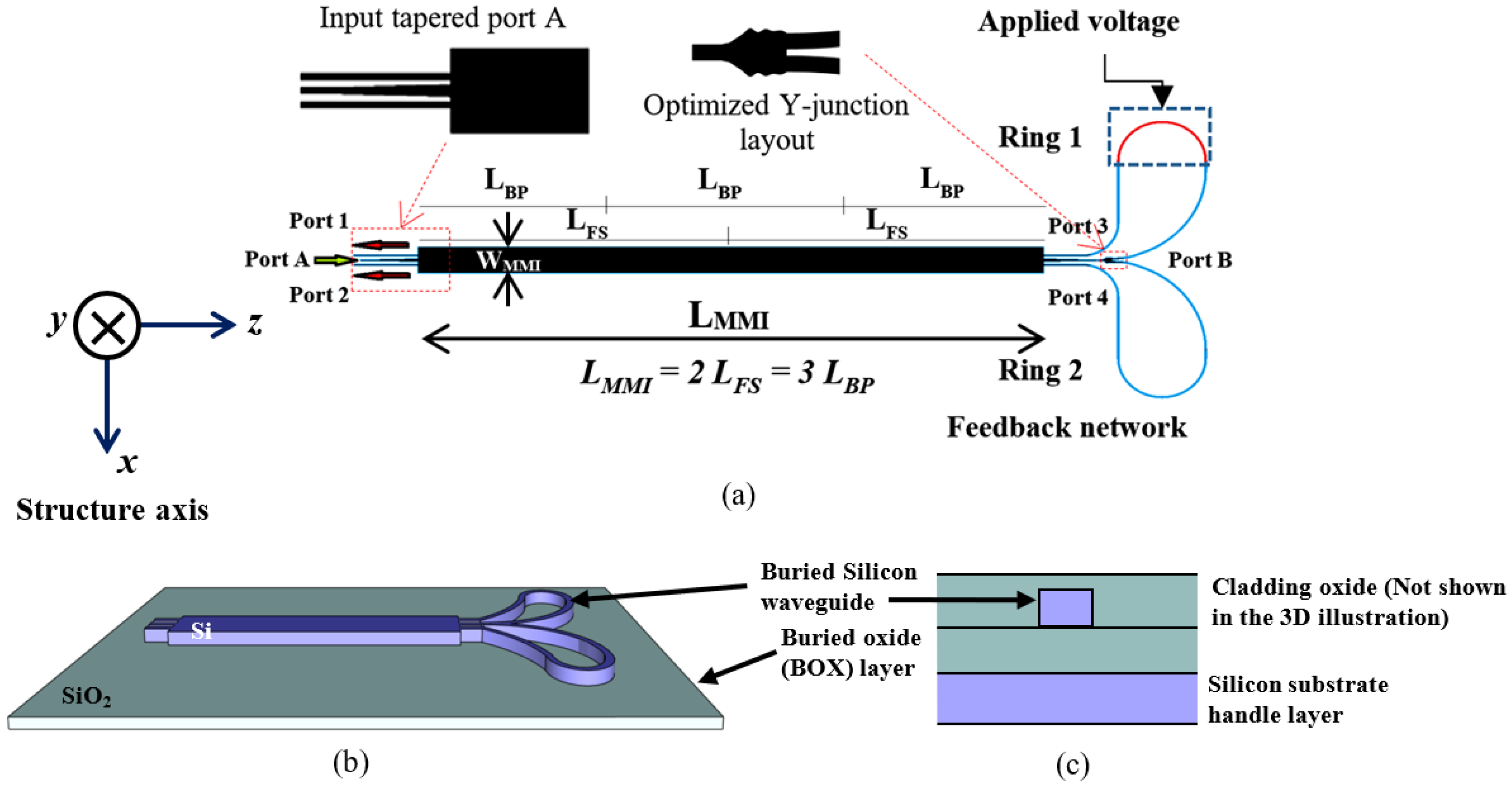
Figure 1. Conventional MMI design layout: (a) detailed structure, insets show input tapered port A, the optimized Y-junction, and the phase shifter ring from left to right, respectively; (b) 3D illustration of the structure showing the materials used; (c) cross-sectional view perpendicular to the z-axis (propagation direction).
Photonics 11 00221 g001
Figure 2. Electric field contour map of the output when the phase difference between the two ports is (a) 90°; (b) −90°.
Photonics 11 00221 g002
Figure 3. Transmission spectrum of the router when (a) Port 1 is in the ON state; (b) Port 2 is in the ON state.
Photonics 11 00221 g003
Figure 4. Three-dimensional plot of the electric field |E| in the structure (input electric field unit of magnitude 1 V/m).
Photonics 11 00221 g004
Figure 5. Angled MMI design layout, the red inset shows the optimized Y-junction, and the blue inset shows the phase shifter ring where voltage is applied.
Photonics 11 00221 g005
Figure 6. Transmission spectrum for the angled inputs when (a) Port 1 is in the ON state; (b) Port 2 is in the ON state.
Photonics 11 00221 g006
Figure 7. Transmission spectrum for the paired inputs: (a) for a 90° phase difference; (b) for a −90° phase difference.
Photonics 11 00221 g007
Figure 8. Electron distribution profile at the cross-section of the phase shifter at (a) no applied voltage, (b) −6 V applied voltage.
Photonics 11 00221 g008
Figure 9. (a) Cross sectional view of the silicon pn-junction phase shifter waveguide, and (b) 3D view of the phase-shifter ring.
Photonics 11 00221 g009
Figure 10. Effects of reverse applied voltage on (a) loss and (b) the effective index change.
Photonics 11 00221 g010
Figure 11. Phase change with the applied voltage for different lengths.
Photonics 11 00221 g011
Table 1. Comparison of this work with state-of-the-art MMI routers.
WorkCrosstalk (dB)Insertion Loss (dB)Type of Study
This work18.25Simulation
Ref [24]12.71Simulation
Ref [25]221.65Simulation/Experimental
Ref [26]23.350.82Simulation
Ref [39]200.84Simulation
Disclaimer/Publisher’s Note: The statements, opinions and data contained in all publications are solely those of the individual author(s) and contributor(s) and not of MDPI and/or the editor(s). MDPI and/or the editor(s) disclaim responsibility for any injury to people or property resulting from any ideas, methods, instructions or products referred to in the content.