Article

A Theoretical Study on Mid-Infrared Difference Frequency Generation Based on Periodically Poled Thin-Film LiNbO3

1
Key Lab of Optoelectronic Information Technology (Ministry of Education), and Key Lab of Micro-Opto-Electro-Mechanical Systems (MOEMS) Technology (Ministry of Education), Department of Opto-Electronics and Information Engineering, School of Precision Instruments and Opto-Electronics Engineering, Tianjin University, Tianjin 300072, China
2
School of Semiconductor and Physics, North University of China, Taiyuan 030051, China
*
Author to whom correspondence should be addressed.
These authors contributed equally to this work.
Photonics 2023, 10(4), 478; https://doi.org/10.3390/photonics10040478
Submission received: 23 March 2023 / Revised: 16 April 2023 / Accepted: 17 April 2023 / Published: 21 April 2023
(This article belongs to the Special Issue Integrated Waveguide-Based Photonic Devices)

Abstract

:
A mid-infrared difference frequency generator (DFG) based on a periodically poled thin-film lithium niobate rib waveguide on a sapphire substrate is theoretically studied. A mode analysis is carried out at the mid-infrared region, and the analysis focuses on the effects of waveguide geometry on effective refractive indices of a few lower-order modes. A complete theory suitable for modeling a DFG based on a waveguide structure is described. Its validity is confirmed by comparing the theoretical results with previously reported experimental data. Explicit expressions are presented for nonlinear conversion efficiency, thermal tunability and quasi-phase matching (QPM) bandwidth. The effects of waveguide geometry and mode hybridization on the effective mode field area and mode overlap factor, which are either inversely or linearly proportional to nonlinear conversion efficiency, are studied in detail. In this article, an optimized mid-infrared DFG with improved geometry that exhibits excellent performance, including a higher nonlinear conversion efficiency of 230–273% W−1cm−2 in the temperature range of 20–120 °C; a larger temperature tunability of 2.2 nm/°C; a larger QPM bandwidth of ~130 nm; and a higher idler wave output power, as much as −2 dBm when Pp = 20 dBm and Ps = 11.5 dBm, is suggested.

1. Introduction

Driven by great application potential in spectroscopy, some mid-infrared (mid-IR) coherent sources, which can be applied to modern spectral measurement techniques such as dual-comb spectroscopy, Michelson-based Fourier transform spectroscopy and high-resolution crossed-dispersion spectroscopy, have been developed in the past decade [1]. These mid-IR light sources play a very important role in environmental science, analytical chemistry and biomedicine. Among them, semiconductor mid-IR lasers are currently already commercially available. Next-generation quantum well and quantum dot lasers operating at mid-IR appear to be promising coherent sources [2,3]. Another type of mid-IR source works based on nonlinear frequency conversion. Over the past years, much effort has been devoted to the implementation of small-size and efficient nonlinear frequency conversion mid-IR sources. This effort has led to progress in mid-IR sources from a large cross-section waveguide [4,5] to a nano-photonic waveguide or micro-resonator [6]. Based on the nano-photonic waveguide, highly efficient χ(2) -based frequency conversion in the near-IR region has been demonstrated by making use of some low-loss thin-film waveguide platforms, such as LiNbO3 (LN) [7], AlGaAs [8] and Si3N4 [9]. Among them, the thin-film LiNbO3-on-insulator (TF-LNOI) waveguide is a promising and well-established platform used to develop highly efficient nonlinear frequency conversion devices [7,10], as well as electro-optic (EO) devices [11,12,13]. TF-LN frequency conversion devices can be divided into two categories according to their phase matching method: periodically polarized lithium niobate thin film (PPTFLN) devices based on quasi-phase-matching (QPM) and TF-LN waveguide devices based on mode-phase-matching (MPM). The fabrication process of MPM devices is simple, and only the waveguide structure needs to be designed according to the wavelength requirements. However, low nonlinear conversion efficiency is a disadvantage that cannot be ignored for MPM devices. The main reason for their low efficiency is that, in order to achieve the mode-phase-matched condition, the polarization of the output light is always different from that of the input light, which causes the highest nonlinear coefficient d33 of lithium niobate to not be used. In comparison, QPM devices can easily complete the phase matching process by regulating the polarization period, thus obtaining higher nonlinear conversion efficiency with d33. QPM nonlinear devices can be extended to the mid-IR region by making use of the LN’s merit of a wide transparent wavelength range up to 4.5 µm [14,15]. However, silica, which is usually used as the insulator of the TF-LNOI, suffers from strong absorption in the spectral region λ > 2.5 µm [16] and, thereby, causes significant signal wave attenuation there. Instead, sapphire shows high transparency up to the 4.5 µm wavelength region. It is a more appropriate insulator substrate than silica for a TF-LNOI worked in the mid-infrared region. In other words, TF-LN-on-sapphire is a more promising platform than the usual LN-on-silica for the mid-IR applications, though sapphire has a slightly larger refractive index than silica, which causes a decrease in refractive index contrast of TF-LNOI by ~0.3. The refractive index change of the insulator substrate considerably affects the waveguiding characteristics of the TF-LNOI and, hence, the performance of the relevant devices. It is thus essential to carry out an overall theoretical study on the waveguide properties and performance of the relevant devices. However, relevant, detailed theoretical studies on the relation between nonlinear performance and waveguide properties have yet to be found, as far as we know. The present work carried out a study on a mid-IR difference frequency generator (DFG) based on the periodically poled TF-LN-on-sapphire rib waveguide, along with a previous experimental demonstration of such a device [17]. Our work aims to determine the waveguiding characteristics and three key performance parameters: nonlinear conversion efficiency, temperature tunability and quasi-phase matching (QPM) bandwidth. Previously, some researchers have proposed a step-chirped quasi-phase-matched grating structure to improve the QPM bandwidth of these devices [18,19]. In this paper, for general PPTFLN devices, a scheme for achieving broader QPM bandwidth and higher thermal tunability is proposed: the QPM bandwidth and thermal tunability can be optimized by regulating the GVM (group velocity mismatch) factor, which will be described in Section 3 by deducing the theoretical expression. Finally, an optimized mid-IR DFG based on periodically poled TF-LN-on-sapphire rib waveguide is proposed.

2. Device Structure, Design Considerations and Calculation Method

The waveguide considered in the present study is a rib-type TF-LN-on-sapphire waveguide. Figure 1a shows a structural schematic of the channel waveguide cross section, with W denoting the rib width, h denoting the rib height or etching depth, and H denoting the thickness of the LN thin film. During practical fabrication of the TF-LNOI rib waveguide, i.e., usually dry etching (reactive ion etching, RIE) in combination with chemical mechanical polishing (CMP), the etching process always produces an inclined side of the rib waveguide with an inclination angle α (=78.5° typically [17]), as shown in Figure 1a. It is worth noting that the z axis in Figure 1 represents the crystal axis.
Figure 1b shows a 3D view of the mid-IR QPM-DFG based on a periodically poled TF-LN-on-sapphire channel waveguide. Assume that the ferroelectric domain has a pitch Λ. The device has a simple working principle. The QPM nonlinear interaction of incident pump (λp) and signal wave (λs) induces the generation of an idler wave (λi) when the three waves meet both the laws of energy and momentum conservation, as described later.
Some design considerations are detailed below.
(1) X-cut/Y-propagation scheme
For an X-cut LNOI, the electrodes used for periodical poling only need to be put on the top surface of the LN, and the electrode spacing is relatively small [20,21]. For a Z-cut LNOI, however, the electrodes need to be fabricated not only on the top surface but also underneath the substrate, leading to larger electrode spacing. Moreover, in the case of Z-cut LN poling, the electric field needs to penetrate through the insulator layer, making the reversed domains difficult to maintain persistently after the poling process [22]. In other words, the domain poling of an X-cut LNOI is more convenient than that of a Z-cut one, and the reversed domain of the X-cut LN can be maintained more persistently. In addition, in order to utilize the largest second-order nonlinear coefficient d33 of the LN crystal, a transverse-electric (TE) wave propagation scheme should be selected. Thus, an X-cut/Y-propagation scheme is adopted in the present study.
(2) Pump and signal waves
In order to generate a mid-IR idler wave at ~3 μm using the QPM-DFG, we consider that a commercially available 980 nm laser diode is used as the pump wave source and a laser tunable in the wavelength range of 1340–1440 nm (a commercially available Santec TSL-510 tunable laser, for example) is selected as the signal wave source. It is worthwhile to mention that Mishra et al. employed a slightly different pump and signal wave wavelengths of 1.064 and 1.5–1.7 μm in their experimental study [17].
(3) Use of MgO-doped TF-LN-on-sapphire
As we know, an undoped LN suffers from a serious photorefractive effect in both the visible and NIR (λ < 1 μm) regions. To suppress this detrimental effect, here, we propose employing a 5 mol% MgO-doped TF-LN-on-sapphire. Fortunately, all relevant knowledge about it, including the refractive index dispersion relation [23] and second-order nonlinear tensor components [24], is known.
(4) Simulation model
Lumerical MODE Solutions simulation software was used. The mesh size was set to 10 nm, which was determined according to a convergence analysis. Finally, a PML boundary was used. Waveguide propagation losses, which are affected by fabrication, exist in all devices. Considering that the losses will vary with different crafts, a lossless model is used in our theoretical study to research the influence of waveguide dimensions on nonlinear performance through a complete simulation and provide guidance for the design and fabrication of high-performance mid-infrared light source devices. If the losses are considered, the nonlinear conversion efficiency will decrease, while the QPM bandwidth and thermal tunability will be hardly influenced. However, that does not affect our conclusion, which can be further confirmed by published work with the lossless model [7,25].
Moreover, it is worth mentioning that fabrication errors due to ferroelectric domain engineering exists. Firstly, a dimension error generated during the lithography process of a surface electrode will lead to deviation in the polarization period Λ, which affects the central wavelength of the device. Secondly, it is easy to generate an excessive local electric field due to the skin effect of an electric charge at the edge of the metal surface electrode, which may lead to a breakdown in the crystal.

3. Theory, Results and Discussion

3.1. Mode Analysis

As shown later, the performance of a DFG based on a waveguide structure is closely related to the waveguiding characteristics of the mode guided, aiming to produce the TF-LN-on-sapphire rib-type waveguide depicted in Figure 1a.
Some considerations taken into account in the input parameters are described briefly below. When the wavelength of input pump wave is fixed at 980 nm and that of input signal wave is tunable from 1340 to 1440 nm, an idler wavelength tunable from 3.0 to 3.6 μm is generated. The present mode analysis at the central wavelength λ = 3.3 μm focuses on the effects of waveguide geometries on the waveguiding characteristics.
Figure 2a–c show effective refractive indices neff of a few lower-order modes—TE00, TM00 and TE10—calculated as a function of rib width W when the rib has three different heights—h = 0.5, 0.7 and 0.9 μm. The other input parameters are α = 78.5°, H = 1 μm and λ = 3.3 μm. Note that the value of the inclination angle α = 78.5° is taken from the earlier experimental work in Ref. [17]. Here, we chose a thicker LN film of H = 1 μm (the most common thickness is 0.7 μm [26]). Our reason for such a choice is that the longer the operating wavelength, the larger the waveguide cross section required to realize single-mode propagation. In order to find the waveguide dimensions where only the TE00 mode is conductive while the TM00 and TE10 modes are cut off, the effective refractive indices of three low-order modes are calculated in total. It can be seen that the cutoff widths of the TE00 mode and TM00 mode are similar, so we can only choose the dimensions where only the TE10 mode is cut off. One can see from Figure 2a–c that the mode index increases with the rib width W but decreases with the increase in the mode order for a given polarization state and given W and h values. This observation is expected from the waveguide theory.
Moreover, the rib height h considerably affects the waveguiding characteristics. The increase in etching depth h is equivalent to the decrease in rib width W. As a result, the mode index decreases as the rib height h increases. The observation may also be explained on the basis of the slab waveguide thickness effect on the mode index. For a slab waveguide, the mode index increases with its thickness. The increase in the rib thickness h is equivalent to the decrease in slab thickness and, thereby, of the mode index. The considerable rib height effect on the mode index leads to a definite effect on the single-mode condition. One can see from Figure 2a–c that the cutoff rib width of the TE10 mode is similar—2.5, 3.25 and 3.5 μm for the rib height h = 0.5, 0.7 and 0.9 μm, respectively.
The neff curves at the signal and pump wavelengths are provided in Figure 3a–f. It shows that the cutoff widths of the TE00 and TM00 modes of the pump light and signal light are less than 0.5 μm and that the cutoff width of the TE10 mode of the pump light and signal light is around 1.5 μm. The influences of W and h on neff are the same as that mentioned in Figure 2a–c.
We have further studied the inclination angle α effect on the mode index. Figure 4 shows the effective refractive indices neff of a few lower-order modes—TE00, TM00 and TE10—calculated as a function of rib width W when α = 60°, 70°, 80° and 90°. The other input parameters are H = 1 μm, h = 0.7 μm and λ = 3.3 μm. We can see that the inclination angle α has a small effect on the mode index but noticeably affects the the single-mode condition. As the inclination angle α changes from 60° to 90°, the cutoff rib width of the TE10 mode increases from ~3.0 to ~3.5 μm.
For an optical waveguide, a confinement factor is usually considered to characterize the extent of confinement to a mode guided in it. The factor is defined as the ratio of power flux of a wave confined in the waveguide region to the total power flux on the plane normal to the waveguide axis. As shown later, the confinement factor is directly related to the nonlinear conversion efficiency of the QPM-DFG through the effective mode field area. Next, attention is paid to the confinement factor of the TF-LN-on-sapphire rib-type waveguide studied. Figure 5a shows the confinement factor of the TE00 mode in the rib waveguide as a function of rib width W for three different rib heights: h = 0.5, 0.7 and 0.9 μm (the other parameters are α = 78.5°, H = 1 μm and λ = 3.3 μm). Figure 5b shows the cases for different inclination angles: α = 60°, 70°, 80° and 90° (the other input parameters are H = 1 μm, h = 0.7 μm and λ = 3.3 μm). We note that, as the rib width W is increased, the confinement factor increases strongly in the initial stage, slowly and, then, eventually saturates to a constant, which is similar and less dependent on either the rib height h or the inclination angle α, as shown in Figure 5a,b. In contrast, in the cut-off region, the confinement factor reveals slight effects of rib height h and inclination angle α. These observations may be explained as follows: According to the definition given above, the confinement factor depends mainly on the evanescent field. For an optical waveguide with a given cross-sectional geometry, the larger the confinement factor, the smaller the waveguide loss with regard to the evanescent field and, thereby, the smaller the total waveguide loss. For a smaller W, the mode is in the cut-off state, the evanescent field is significant and the confinement factor has a small value in this case. Moreover, the evanescent field may be influenced by either the rib height h or the inclination angle α. It is thus comprehensible that the confinement factor reveals slight effects of rib height h and inclination angle α. As the W is increased, the mode is far from the cut-off state, the evanescent field decreases gradually and the confinement factor increases correspondingly. As the W is sufficiently large, the mode is well-guided, the evanescent field becomes minor and the confinement factor tends toward a constant. As the minor evanescent field is less influenced by either the rib height h or the inclination angle α, the constant remains essentially fixed for a given H and hardly depends on either the rib height h or the inclination angle α.
It can be seen that a highly slanted waveguide (alpha = 60) result in maximum confinement, which can be explained as follows: the mode field in the waveguide will leak along both lateral and longitudinal. Figure 5 shows that, when W is large enough, the confinement factor is almost 0.75 and remains constant, indicating that there is almost no lateral leakage of the mode in the waveguide, only longitudinal leakage. However, when lateral leakage exists and W remains constant, a larger inclination angle means a larger lateral cross-sectional area of the waveguide, which can reduce lateral leakage, and thus shows a larger confinement factor.
An overall consideration for single-mode operation and mode field confinement factor allows us to give a preliminary rib width W ≈ 3.0 μm.

3.2. Nonlinear Conversion Efficiency

For a QPM-DFG having a nonlinear interaction length L, its nonlinear conversion efficiency ηDFG is given by [27]
η D F G = P i / ( P p P s L 2 ) ,
where Pi is the output power of the idler wave with a wavelength λi, Pp is the power of the input pump wave with a wavelength λp and Ps is the power of the input signal wave with a wavelength λs. These powers are given by [27]
P j = ( E j × H j * ) · z d x d y ,
where j∈{p, s, i}, z is the unit vector along the waveguide axis, and Ej and Hj are the normalized distributions of electric and magnetic fields in the waveguide, respectively. For convenience, an xyz Cartesian reference frame is fixed at the bottom of the silica layer, with the x axis pointing to the width and the y axis pointing to the depth of the rib waveguide, as shown in Figure 1b. The integral in Equation (2) is carried out over the whole plane normal to the propagation direction z.
By solving difference-frequency coupled-mode equations under no pump depletion approximation [27], Equation (1) can be expressed as
η D F G = η n sin c 2 ( Δ β L / 2 ) ,
where ηn is the normalized efficiency. In particular, for a waveguide structure, ηn is given by [27]
η n = 8 π 2 d e f f 2 ε 0 c N p N s N i λ i 2 P p P s P i ,
where c is the light speed in free space; Nj (j = p, s, i) is the effective refractive index of the pump, signal or idler mode; and deff is the effective second-order nonlinear coefficient, given by [27]
d e f f = 2 π W G m , n , k d m , n , k E m , i E n , s E k , p d x d y ,
in which m, n, k ∈ {x, y, z}. Ep, Es and Ei are the normalized electric field distributions of the pump, signal and idler waves, respectively. dm,n,k is the second-order nonlinear tensor matrix element of a nonlinear optical material, such as the LN studied here [27]. The integral in Equation (5) is carried out over the cross section of the related waveguide.
However, for devices using d33, the element in summation with d33 in Equation (3) is much bigger than the other terms in summation, which means that terms without d33 hardly contribute to the value of deff. So, we can simplify Equation (5) as
d e f f = 2 π d 33 W G E z , i E z , s E z , p d x d z ,
Furthermore, we can convert Equation (4) into
η n = 32 d 33 2 ζ 2 ε 0 c N p N s N i λ i 2 A e f f ,
where Aeff is the effective mode field area and ζ is the mode overlap factor, and they are given by
A e f f = P p P s P i ( W G E p 2 E p d x d z W G E s 2 E s d x d z W G E i 2 E i d x d z ) 2 3
ζ = W G E z , i E z , s E z , p d x d z [ W G E p 2 E p d x d z W G E s 2 E s d x d z W G E i 2 E i d x d z ] 1 3
Aeff and ζ are key factors influencing the nonlinear conversion efficiency. It is evident from Equations (7)−(9) that the normalized efficiency ηn decreases with the increased effective mode field area Aeff, while increases with the increase in mode overlap factor ζ. Aeff is closely related to mode confinement of the waveguide. A smaller Aeff means better mode confinement, which results in a higher nonlinear conversion efficiency. ζ represents the overlap in the mode field distribution of the three coupled beams. A larger ζ means stronger coupling of the three beams, which results in a higher nonlinear conversion efficiency.
In Equation (3), ∆β represents the phase mismatch amount along the unit propagation distance [27]:
Δ β = 2 π [ N p ( λ p , T ) / λ p N i ( λ i , T ) / λ i N s ( λ s , T ) / λ s 1 Λ ] ,
where the effective refractive index Nj (j = p, s, i) is dependent on either the wavelength λj or the temperature T. ∆β = 0 means that the quasi-phase matching condition, i.e., the law of momentum conservation, is exactly satisfied.
The validity of the theoretical expressions described above should be demonstrated first. This can be carried out by comparing the calculation results with the relevant experimental data. On the basis of the experimental parameters of the mid-IR QPM-DFG based on the periodically poled LN-on-sapphire channel waveguide (H = 0.63 μm, h = 0.3 μm, W = 3 μm and α = 78.5°) reported in Ref. [17], we have evaluated the normalized nonlinear conversion efficiency ηn of the idler wave as a function of its wavelength. The calculated result is shown in Figure 6 (see red balls) in comparison with the experimental data without the loss corrections (black balls) reported in Ref. [17]. The errors are indicated for both the calculated and experimental data. Our theoretical data have an error of ±20% originating from the uncertainties of the input parameters, including ±10% uncertainty of the second-order nonlinear tensor element [25], about ±5% uncertainty with respect to no pump depletion approximation [27] and about ±5% uncertainty associated with the numerical method. It is unfortunate that Ref. [17] did not specify the error of their experiment results. Here, we assume that their experimental data have a conservative error of ±10%, as indicated in Figure 5. One can see that our theoretical result can be regarded as identical to their experimental data within the error, verifying the validity of the relevant theoretical expressions and the reliability of the theoretical results predicted and given below.
After verification of the relevant theoretical expressions, attention is paid to the key parameters influencing the nonlinear conversion efficiency. Figure 7 shows the effective mode field area Aeff and mode overlap factor ζ of the pump, signal and idler TE00 waves calculated as a function of rib width W in the range of 2.4–4.0 μm for different rib heights h = 0.5, 0.7 and 0.9 μm. The other input parameters are H = 1 μm, α = 78° and λ = 3.3 μm. One can see that, while the mode overlap factor ζ is hardly influenced by either the rib width W or the rib height h, the effective mode field area Aeff is considerably affected by both, and smaller W and larger h favor obtaining a smaller effective mode field area Aeff. The observations are easily understood from the W and h effects on the waveguiding characteristics described above. It can be predicted from the observations that a higher nonlinear conversion efficiency is expected for smaller W and larger h, which result in a smaller effective mode field area Aeff and hence a higher conversion efficiency.
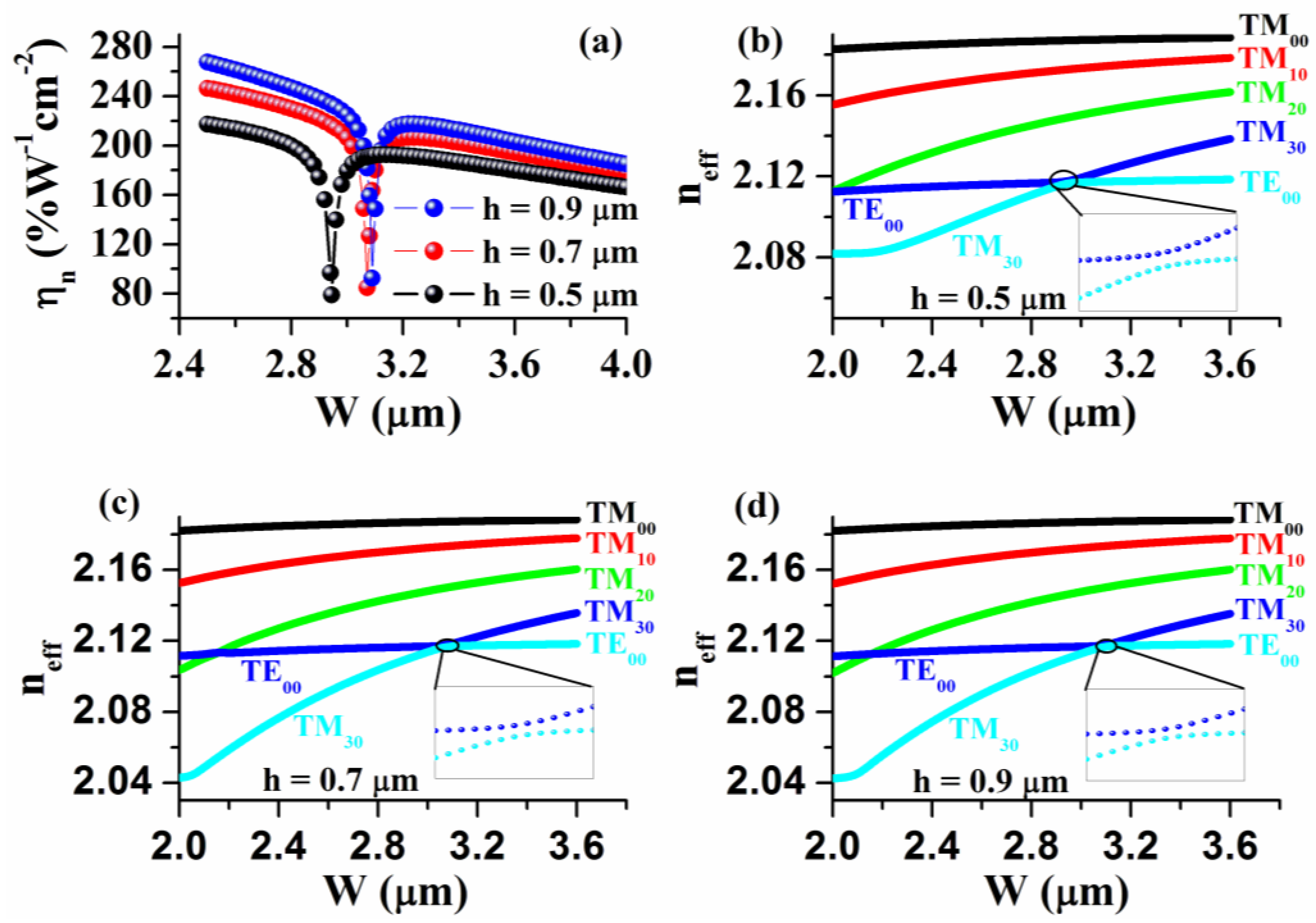
The most remarkable feature in Figure 7 is the appearance of the maximum Aeff and the minimum ζ at W = 2.944, 3.072 and 3.09 μm for the rib heights h = 0.5, 0.7 and 0.9 μm, respectively. These maximum Aeff and minimum ζ values yield minimum normalized efficiency values, as shown in Figure 7a, where the normalized nonlinear conversion efficiency ηn is plotted against the rib width W for the rib height h = 0.5, 0.7 and 0.9 μm. Next, we give a qualitative explanation for the appearance of minimum normalized nonlinear conversion efficiency ηn at a specific rib width W for a given rib height h. It is associated with the occurrence of mode hybridization between the TE00 and TM30 modes. To make the argument clear, here, we exemplify the hybridization between the modes of the 980 nm pump wave. Figure 8b–d shows the effective refractive indices neff of several lower-order pump modes (TE00, TM00, TM10, TM20 and TM30) calculated as a function of rib width W in the case of rib height h = 0.5, 0.7 and 0.9 μm. The other input parameters are H = 1 μm, α = 78° and λ = 0.98 μm. The mode hybridization usually takes place in an asymmetric waveguide when the two modes involved have similar effective indices [28,29,30].
Regarding the presently studied LNOI-on-sapphire rib waveguide, which is asymmetric along the vertical (y) direction, the mode hybridization between the TE00 and TM30 modes occurs in the region of W = 2.944, 3.072 and 3.09 μm for h = 0.5, 0.7 and 0.9 μm, respectively. It is featured by both the variational tendency of the mode index with W and the mode field distribution in that W region. One can see from Figure 8b−d that the tendency of either the TE00 or the TM30 mode index is normal as W is far from the hybridization region. In the W region where the mode hybridization occurs, the two plots of the TE00 and TM30 mode indices are very close but do not actually intersect each other. This is clearly shown in the insets in 
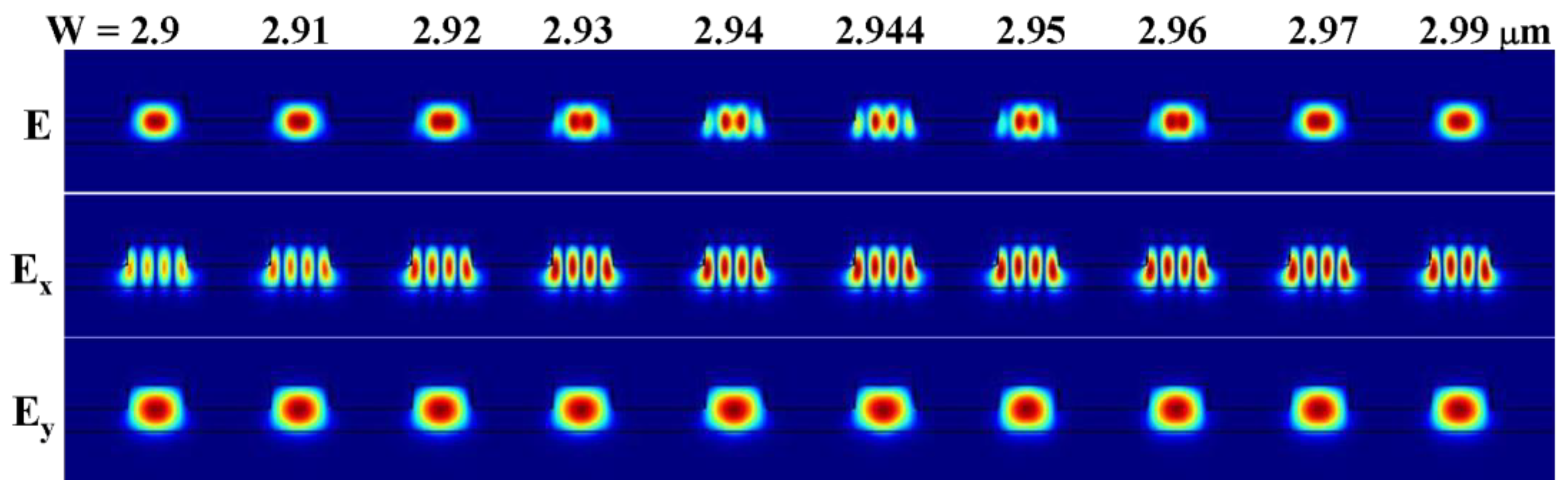
Figure 8b–d, where an expanded view in the hybridization region is shown. Very close mode indices provide the possibility that the two modes couple each other and that mode hybridization happens. The mode hybridization is also featured by the mode field distribution in the related rib width region. As a representative figure, Figure 9 shows the evolution of two-dimensional distributions of electric field E and its two components Ex and Ey of the fundamental mode TE00 with the rib width W in the range of 2.9−2.99 μm in the case of rib height h = 0.5 μm. Because the TE00 mode occurs when the TM30 mode is not related to the normalized efficiency ηn, only the evolution feature of the electric field distributions with regard to the TE00 mode is followed here. Note that mode hybridization occurs at W ≈ 2.944 μm in the case of rib height h = 0.5 μm. One can see that, in the W = 2.944 μm region where the mode hybridization occurs, the electric field distribution of the TE00 mode is significantly different from that in the W region far from the mode hybridization zone. The significant change in mode field distribution in the mode hybridization zone makes neither the mode confinement nor the mode overlap become worse, which leads to a substantial change in the effective mode field area Aeff and mode overlap factor ζ and, hence, the normalized efficiency ηn, as shown in Figure 7 and Figure 8a. It is thus comprehensible that a minimum normalized nonlinear conversion efficiency ηn appears at a specific rib width W for a given rib height h.
We have also studied the inclination angle α effect on the conversion efficiency. Figure 10 shows the normalized efficiency ηn calculated as a function of rib width W in the range of 2.5–4.0 μm for four different inclination angles: α = 60°, 70°, 80° and 90°. The other parameters are H = 1 μm and h = 0.7 μm. As expected, the larger α, the higher the efficiency ηn. A 90° inclination angle allows for the maximum conversion efficiency to be obtained, as shown in Figure 10. We also note that both the minimum ηn value and its location change with α more obviously than with rib height h.

3.3. Thermal Tunability and QPM Bandwidth

It is essential to further study the thermal tunability and QPM bandwidth of the device studied. According to Equation (10), the quasi−phase matching condition is given by
N p ( λ p , T ) / λ p N i ( λ i , T ) / λ i N s ( λ s , T ) / λ s 1 Λ = 0 ,
The thermal tunability can be studied on the basis of Equation (11) and the law of energy conservation [27].
1 / λ p = 1 / λ i + 1 / λ s ,
From Equations (11) and (12), one can derive the expression for thermal sensitivity of the idler’s wavelength λi or angular frequency ωi, i.e., ∂λi/∂T or ∂ωi/∂T, which characterizes the thermal tunability of the idler wave.
λ i T = λ i 2 N p T 1 λ p N i T 1 λ i N s T 1 λ s ( N s λ s N s λ s ) ( N i λ i N i λ i ) ,
ω i T = N p T ω p N i T ω i N s T ω s ( N i ω i ω i + N i ) ( N s ω s ω s + N s ) ,
Note that, in the derivation, the pump wavelength remains constant while the wavelengths of both signal and idler waves are variables.
Since an LNOI waveguide has a smaller cross-section geometry, a mode guided in it usually has significant waveguide dispersion. Group velocity dispersion should be considered. For the pump, signal and idler waves, their involved group mode indices, named Njg (j = s, i), are given by
N j g = N j λ j N j λ j = N j + ω j N j ω j = c / υ j g ,
where υjg (j = s, i) denotes the group velocity. Inserting Equation (15) into Equations (13) and (14), we have
λ i T = λ i 2 N p T 1 λ p N i T 1 λ i N s T 1 λ s c ( 1 υ s g 1 υ i g ) = λ i 2 N p T 1 λ p N i T 1 λ i N s T 1 λ s c G V M ,
ω i T = N p T ω p N i T ω i N s T ω s c ( 1 υ i g 1 υ s g ) = N p T ω p N i T ω i N s T ω s c G V M ,
where G V M = 1 υ s g 1 υ i g reflects group velocity mismatch between the signal and idler waves. One can see from Equations (16) and (17) that the thermal sensitivity is determined mainly by the thermo-optic coefficient of the material, wavelengths or frequencies of the pump, signal and idler waves, as well as the GVM factor. For a given material and the given pump and signal waves, the tunability of the idler wave is controlled by the GVM.
For QPM bandwidth, we combine Equation (3) with Equation (10) and we obtain
K = π L [ N p ( λ p , T ) / λ p N i ( λ i , T ) / λ i N s ( λ s , T ) / λ s 1 Λ ] ,
In Equation (3), K equals ΔβL/2, then we differentiate both sides of Equation (3) using Equation (12), and we obtain
Δ K = π L Δ λ i ( N i λ i λ i N i λ i 2 N s λ s λ s N s λ i 2 ) ,
As for QPM bandwidth, the equation sincK/2) = 1/2 needs to be ensured. In this article, the value of ΔK is approximated to π for ease of calculation, which is an approximation with a tiny error. Finally, we substitute Equation (15) into Equation (19), and the QPM bandwidth can be expressed as
Δ λ = λ 2 G V M c L ,
The absolute value of GVM is used in Equation (20) because the bandwidth is always positive. Equation (20) shows that the QPM bandwidth also depends on the GVM, together with the length L of a periodically poled TF-LNOI. By making use of an optical waveguide with a smaller GVM, which can be obtained by optimizing the waveguide dimensions, not only a higher thermal tunability but also a larger QPM bandwidth are expected.
To understand the GVM effect on both thermal tunability and QPM bandwidth, at the wavelengths λp = 980 nm, λs = 1390 nm and λi = 3322.4 nm, we have simulated, firstly, the waveguide properties and, then, the nonlinear frequency conversion features of three periodically poled TF-LN-on-sapphire rib waveguides with different structural parameters, as follows:
WG#1: H = 1.0 μm, h = 0.70 μm, W = 2.8 μm, α = 78°, Λ = 7.68 μm, L = 4 mm;
WG#2: H = 0.9 μm, h = 0.60 μm, W = 2.3 μm, α = 78°, Λ = 6.90 μm, L = 4 mm;
WG#3: H = 0.7 μm, h = 0.35 μm, W = 3.7 μm, α = 78°, Λ = 6.71 μm, L = 4 mm.
These structural parameters are chosen on the basis of the resultant GVM values, as given below. The simulation on the waveguide properties gives, firstly, the dispersion relation and the derivative (with regard to the wavelength) of the mode index in the proximity of the signal and idler wavelengths; then, the group mode indices Njg (j = s, i); and finally, the GVM values of the three waveguide structures studied, i.e., GVM = 69.4, −160.8 and –320.4 fs/mm for WG#1, WG#2 and WG#3, respectively. According to Equation (3), we calculated the QPM curves of the studied three waveguide structures at two different temperatures of 20 and 60 °C. The calculated results are shown in Figure 11a–c. The black plot corresponds to the temperature at 20 °C and the red plot to that at 60 °C. For the WG1 waveguide, which has a positive GVM value 69.4 fs/mm, as the temperature is increased from 20 to 60 °C, the QPM peak blue-shifts from 3322.4 to 3234.5 nm, yielding an averaged thermal tunability of ∂λi/∂T = −2.2 nm/°C. However, for the WG#2 and WG#3 waveguides, both of which have negative GVM values of –160.8 and –320.4 fs/mm, respectively, the QPM peak red-shifts with a rise in temperature. As the temperature is increased from 20 to 60 °C, the QPM peak red-shifts by 95.1 and 31.9 nm, yielding an averaged thermal tunability of ∂λi/∂T = 2.4 and 0.8 nm/°C, respectively. On the other hand, we have also evaluated the thermal tunability of each waveguide by directly using Equation (16), and consistent results are obtained for each case, verifying the validity of Equation (16). This is also true for the QPM bandwidth. Figure 11d shows a comparison of the phase matching curves of three waveguides—WG#1, WG#2 and WG#3—at 20 °C.
The three curves are taken from Figure 11a–c. From the three curves, we have obtained the QPM bandwidths 145, 63 and 31 nm, respectively, consistent with the results evaluated from Equation (20): 133, 57 and 28 nm, respectively.
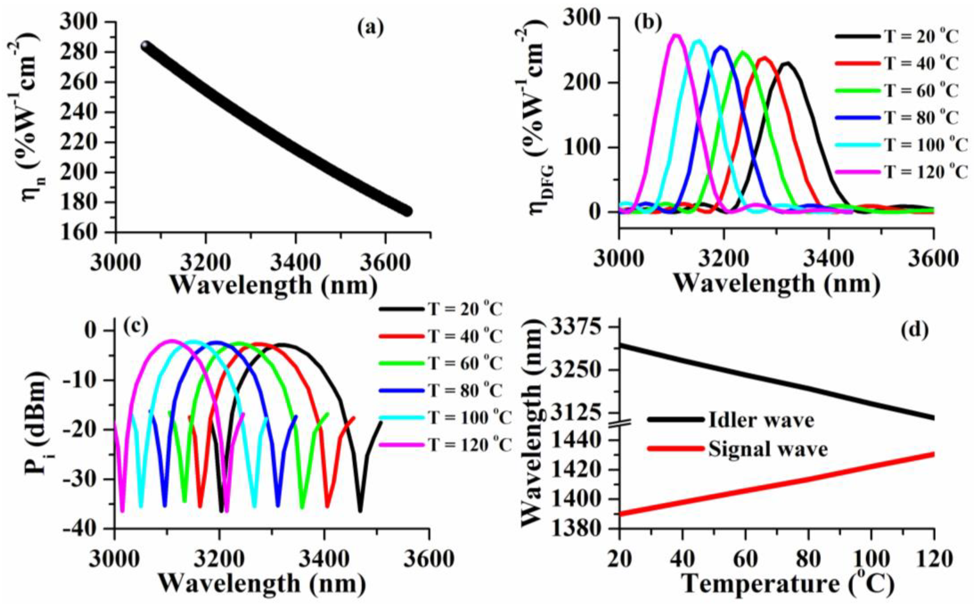
We can see that a DFG based on the WG#1 waveguide with H = 1.0 μm, h = 0.7 μm, W = 2.8 μm, α = 78°, Λ = 7.68 μm and L = 4 mm exhibits a higher thermal tunability and a larger QPM bandwidth than the other two, WG#2 and WG#3. It is essential to further study the efficiency and output power of the idler wave of the DFG device based on the WG#1 waveguide. In terms of the DFG based on the WG#1 waveguide, we have studied the wavelength dependence of normalized efficiency ηn, as well as temperature effects on both the efficiency ηDFG and output power Pi of the idler wave when Pp = 20 dBm and Ps = 11.5 dBm, which is the most common power for commercial lasers. The results are shown in Figure 12a–c. Similar to the feature observed in Figure 6, the normalized efficiency is wavelength-independent and decreases remarkably with an increased wavelength of the idler wave, as shown in Figure 12a. As the idler wavelength is increased from 3068 to 3648 nm, ηn decreases almost linearly from 284 to 174% W−1cm−2.
We can see from Figure 12b that the QPM peak blue-shifts from 3322.4 to 3104.8 nm as the temperature is increased from 20 to 120 °C, yielding an averaged thermal tunability of –2.2 nm/°C, consistent with the results obtained from Figure 11a. We can further see from Figure 12b that the higher the temperature, the larger the peaking ηDFG value. As the temperature goes from 20 to 120 °C, the peaking ηDFG value increases from 230 to 273.2% W−1cm−2 and increases by ~20%. In addition to the increase in ηDFG, operation at higher temperature also favors the suppression of detrimental photorefractive effects [31]. The output power Pi of the idler wave shows similar temperature effects. As shown in Figure 12c, the Pi peak blue-shifts and its peaking value increases slightly and almost linearly with a rise in operation temperature (the increase is by 0.8 dB as the temperature goes from 20 to 120 °C). The largest output power of the idler wave is similar to –2 dBm. Figure 12d shows the temperature tuning curve of the DFG device based on the WG#1 waveguide (note that the vertical axis is broken to more clearly show the change in the signal or idler wavelength with temperature). From the tuning curve, we obtain a temperature tunability similar to –2.2 nm/°C, consistent with the result given above.
Finally, we have also comparatively studied the DFG performance of the higher-order mode TE10 of the idler wave. The results show that the normalized efficiency degrades by two more times than the case of the TE00 fundamental mode because of the quite different field distributions in the TE00 and TE10 modes.

3.4. Discussion

The simulation results of the device have been contrasted with other mid-IR nonlinear devices in Table 1, focusing on nonlinear conversion efficiency and QPM bandwidth. Through a comparison, it can be seen that an APPLN (aperiodically poled lithium-niobate) structure and an OPO (optical parametric oscillator) structure can realize ultra-high bandwidth mid-infrared light sources, but its nonlinear conversion efficiency is much lower than that of a PPTFLN device. Compared with the device in Ref. [17] with the same structure, in this work, the waveguide dimensions are optimized for a small GVM factor and a high nonlinear conversion efficiency. Finally, a mid-infrared light source device that gives consideration to three important properties—nonlinear conversion efficiency, QPM bandwidth and thermal tunability—is realized, which provides a new general and easy-to-prepare strategy for the development of a mid-infrared light source.

4. Conclusions

(1) A complete theory valid for modeling a DFG based on a waveguide structure is given and verified based on consistency between the theoretical and previously reported experimental results. Explicit expressions are presented for nonlinear conversion efficiency, thermal tunability and quasi-phase matching (QPM) bandwidth.
(2) The nonlinear conversion efficiency is linearly proportional to the mode overlap factor and inversely proportional to the effective mode field area. The study shows that the mode overlap factor is hardly influenced, while the effective mode field area is considerably influenced by the waveguide geometry.
(3) This study also shows that mode hybridization causes an increase in the effective mode field area but a decrease in the mode overlap factor and, thereby, a decrease in the nonlinear conversion efficiency.
(4) It is shown that the matching wavelength can be tuned effectively by changing the temperature. The change in temperature also slightly modifies the nonlinear conversion efficiency.
(5) It is also shown that both thermal tunability and QPM bandwidth are inversely proportional to the GVM factor, which is associated with the waveguide geometry.
(6) Finally, an optimized mid-infrared DFG with H = 1.0 μm, h = 0.7 μm, W = 2.8 μm, α = 78°, Λ = 7.68 μm and L = 4 mm has been proposed. The optimized device has a higher nonlinear conversion efficiency of 230–273% W−1cm−2 in the temperature range of 20–120 °C; a larger temperature tunability of 2.2 nm/°C; a larger QPM bandwidth of ~130 nm; and a higher idler wave output power, as much as −2 dBm when Pp = 20 dBm and Ps = 11.5 dBm.

Author Contributions

Conceptualization, R.J. and M.L.; methodology, R.J. and M.L.; software, R.J. and J.L.; validation, R.J., D.Z. and P.H.; formal analysis, D.Z.; investigation, M.L.; resources, R.J.; data curation, R.J.; writing—original draft preparation, R.J.; writing—review and editing, D.Z.; visualization, D.Z.; supervision, D.Z.; project administration, R.J.; funding acquisition, D.Z. All authors have read and agreed to the published version of the manuscript.

Funding

This research was funded by National Natural Science Foundation of China under Project no. 61875148.

Institutional Review Board Statement

Not applicable.

Informed Consent Statement

Not applicable.

Data Availability Statement

Data underlying the results presented in this paper are not publicly available at this time but may be obtained from the authors upon reasonable request.

Acknowledgments

This work was supported by the National Natural Science Foundation of China under Project no. 61875148.

Conflicts of Interest

The authors declare that there are no conflict of interest with regard to the present paper. The authors also declare that they have no known competing financial interests or personal relationships that could have appeared to influence the work reported in this paper.

References

  1. Nathalie, P.; Theodor, W.H. Mid-IR spectroscopic sensing. Opt. Photon. News 2019, 30, 26–33. [Google Scholar] [CrossRef]
  2. Yao, Y.; Hoffman, A.J.; Gmachl, C.F. Mid-infrared quantum cascade lasers. Nat. Photon. 2012, 6, 432–439. [Google Scholar] [CrossRef]
  3. Jung, D.; Bank, S.; Lee, M.L.; Wasserman, D. Next-generation mid-infrared sources. J. Opt. 2017, 19, 123001. [Google Scholar] [CrossRef]
  4. Büchter, K.-D.F.; Herrmann, H.; Langrock, C.; Fejer, M.M.; Sohler, W. All-optical Ti:PPLN wavelength conversion modules for free-space optical transmission links in the mid-infrared. Opt. Lett. 2009, 34, 470–472. [Google Scholar] [CrossRef] [PubMed]
  5. Kowligy, A.S.; Lind, A.; Hickstein, D.D.; Carlson, D.R.; Timmers, H.; Nader, N.; Cruz, F.C.; Ycas, G.; Papp, S.B.; Diddams, S.A. Mid-infrared frequency comb generation via cascaded quadratic nonlinearities in quasi-phase-matched waveguides. Opt. Lett. 2018, 43, 1678–1681. [Google Scholar] [CrossRef]
  6. Gaeta, A.L.; Lipson, M.; Kippenberg, T.J. Photonic-chip-based frequency combs. Nat. Photon. 2019, 13, 158–169. [Google Scholar] [CrossRef]
  7. Wang, C.; Langrock, C.; Marandi, A.; Jankowski, M.; Zhang, M.; Desiatov, B.; Fejer, M.M.; Lončar, M. Ultrahigh-efficiency wavelength conversion in nanophotonic periodically poled lithium niobate waveguides. Optica 2018, 5, 1438–1441. [Google Scholar] [CrossRef]
  8. Chang, L.; Boes, A.; Pintus, P.; Peters, J.D.; Kennedy, M.; Guo, X.-W.; Volet, N.; Yu, S.-P.; Papp, S.B.; Bowers, J.E. Strong frequency conversion in heterogeneously integrated GaAs resonators. APL Photon. 2019, 4, 036103. [Google Scholar] [CrossRef]
  9. Lu, X.; Moille, G.; Rao, A.; Westly, D.A.; Srinivasan, K. Efficient photoinduced second-harmonic generation in silicon nitride photonics. Nat. Photon. 2020, 15, 131–136. [Google Scholar] [CrossRef]
  10. Jankowski, M.; Langrock, C.; Desiatov, B.; Marandi, A.; Wang, C.; Zhang, M.; Phillips, C.R.; Lončar, M.; Fejer, M.M. Ultrabroadband nonlinear optics in nanophotonic periodically poled lithium niobate waveguides. Optica 2020, 7, 40–46. [Google Scholar] [CrossRef]
  11. Wang, C.; Zhang, M.; Chen, X.; Bertrand, M.; Shams-Ansari, A.; Chandrasekhar, S.; Winzer, P.; Lončar, M. Integrated lithium niobate electro-optic modulators operating at CMOS-compatible voltages. Nature 2018, 562, 101–104. [Google Scholar] [CrossRef] [PubMed]
  12. Zhang, M.; Buscaino, B.; Wang, C.; Shams-Ansari, A.; Reimer, C.; Zhu, R.; Kahn, J.M.; Lončar, M. Broadband electro-optic frequency comb generation in a lithium niobate microring resonator. Nature 2019, 568, 373–377. [Google Scholar] [CrossRef] [PubMed]
  13. Yu, M.; Wang, C.; Zhang, M.; Loncar, M. Chip-based lithium-niobate frequency combs. IEEE Photon. Technol. Lett. 2019, 31, 1894–1897. [Google Scholar] [CrossRef]
  14. Myers, L.E.; Bosenberg, W.R. Periodically poled lithium niobate and quasi-phase-matched optical parametric oscillators. IEEE J. Quantum Electron. 1997, 33, 1663–1672. [Google Scholar] [CrossRef]
  15. He, J.; Li, Y. Design of on-chip mid-IR frequency comb with ultra-low power pump in near-IR. Opt. Express 2020, 28, 30771–30783. [Google Scholar] [CrossRef]
  16. Kitamura, R.; Pilon, L.; Jonasz, M. Optical constants of silica glass from extreme ultraviolet to far infrared at near room temperature. Appl. Opt. 2007, 46, 8118–8133. [Google Scholar] [CrossRef]
  17. Mishra, J.; McKenna, T.P.; Ng, E.; Stokowski, H.S.; Jankowski, M.; Langrock, C.; Heydari, D.; Mabuchi, H.; Fejer, M.M.; Safavi-Naeini, A.H. Mid-infrared nonlinear optics in thin-film lithium niobate on sapphire. Optica 2021, 8, 921–924. [Google Scholar] [CrossRef]
  18. Tehranchi, A.; Kashyap, R. Design of novel unapodized and apodized step-chirped quasi-phase matched gratings for broadband frequency converters based on second-harmonic generation. J. Light. Technol. 2008, 26, 343–349. [Google Scholar] [CrossRef]
  19. Tehranchi, A.; Kashyap, R. Flattop Efficient Cascaded χ2 (SFG + DFG)-Based Wideband Wavelength Converters Using Step-Chirped Gratings. IEEE J. Sel. Top. Quantum Electron. 2011, 18, 785–793. [Google Scholar] [CrossRef]
  20. Stanicki, B.J.; Younesi, M.; Löchner, F.J.F.; Thakur, H.; Chang, W.-K.; Geiss, R.; Setzpfandt, F.; Chen, Y.-H.; Pertsch, T. Surface domain engineering in lithium niobate. OSA Contin. 2020, 3, 345. [Google Scholar] [CrossRef]
  21. Zhao, J.; Rüsing, M.; Roeper, M.; Eng, L.M.; Mookherjea, S. Poling thin-film x-cut lithium niobate for quasi-phase matching with sub-micrometer periodicity. J. Appl. Phys. 2020, 127, 193104. [Google Scholar] [CrossRef]
  22. Jia, Y.; Wang, L.; Chen, F. Ion-cut lithium niobate on insulator technology: Recent advances and perspectives. Appl. Phys. Rev. 2021, 8, 011307. [Google Scholar] [CrossRef]
  23. Zelmon, D.E.; Small, D.L.; Jundt, D. Infrared corrected Sellmeier coefficients for congruently grown lithium niobate and 5 mol% magnesium oxide –doped lithium niobate. J. Opt. Soc. Am. B 1997, 14, 3319–3322. [Google Scholar] [CrossRef]
  24. Choy, M.M.; Byer, R.L. Accurate second-order susceptibility measurements of visible and infrared nonlinear crystals. Phys. Rev. B 1976, 14, 1693–1706. [Google Scholar] [CrossRef]
  25. Luo, R.; He, Y.; Liang, H.; Li, M.; Lin, Q. Highly tunable efficient second-harmonic generation in a lithium niobate nanophotonic waveguide. Optica 2018, 5, 1006–1011. [Google Scholar] [CrossRef]
  26. Poberaj, G.; Hu, H.; Sohler, W.; Günter, P. Lithium niobate on insulator (LNOI) for micro-photonic devices. Laser Photon. Rev. 2012, 6, 488–503. [Google Scholar] [CrossRef]
  27. Boyd, R.W. Nonlinear Optics, 3rd ed.; Academic Press: Cambridge, MA, USA, 2008. [Google Scholar]
  28. Pan, A.; Hu, C.; Zeng, C.; Xia, J. Fundamental mode hybridization in a thin film lithium niobate ridge waveguide. Opt. Express 2019, 27, 35659–35669. [Google Scholar] [CrossRef]
  29. Kaushalram, A.; Hegde, G.; Talabattula, S. Mode hybridization analysis in thin film lithium niobate strip multimode waveguides. Sci. Rep. 2020, 10, 16692. [Google Scholar] [CrossRef]
  30. Xu, Q.; Chen, F.; Xue, S.D.; Liu, J.M.; Zhang, D.L.; Hua, P.R. Fundamental mode converter based on tapered LiNbO3-on-insolator photonic wire with a laterally asymmetric structure. Phys. E Low-Dimens. Syst. Nanostruct. 2022, 136, 115028. [Google Scholar] [CrossRef]
  31. Schreiber, G.; Hofmann, D.; Grundkötter, W.; Lee, Y.L.; Suche, H.; Quiring, V.; Ricken, R.; Sohler, W. Nonlinear integrated optical frequency converters with periodically poled Ti:LiNbO3 waveguides. Proc. SPIE 2001, 4277, 144–160. [Google Scholar]
  32. Ulsig, E.Z.; Volet, N. Second-order nonlinear effects in InGaAsP waveguides for efficient wavelength conversion to the mid-infrared, Nonlinear Frequency Generation and Conversion: Materials and Devices XX. SPIE 2021, 11670, 97–105. [Google Scholar] [CrossRef]
  33. Sukeert; Kumar, S.C.; Ebrahim-Zadeh, M. High-Power, Continuous-Wave, Fiber-Pumped Difference-Frequency-Generation at 2.26 μm. IEEE Photon. Technol. Lett. 2021, 33, 627–630. [Google Scholar] [CrossRef]
  34. Feng, X.; Liu, F.; Ning, C.; Shi, J.; Liu, P.; Heng, J.; Zhang, Z. Broadband Mid-IR Light Sources From Difference Frequency Generators Based on a 2-mm-Long Aperiodically-Poled Lithium-Niobate Crystal. IEEE Photon. J. 2021, 13, 1500705. [Google Scholar] [CrossRef]
  35. Wang, K.; Li, X.; Wang, P.; Hua, W.; Wang, Z.; Han, K. Broadband, Continuous-Wave, Mid-Infrared Generation Based on ASE Fiber Source. Photonics 2022, 9, 724. [Google Scholar] [CrossRef]
Figure 1. Structural schematic of mid-IR QPM-DFG based on periodically poled TF-LN-on-sapphire rib-type waveguide: (a) cross-section and (b) 3D view.
Photonics 10 00478 g001
Figure 2. Effective refractive indices neff of the TE00, TM00 and TE10 modes as a function of rib width W for three different rib heights: (a) h = 0.5 μm, (b) h = 0.7 μm and (c) h = 0.9 μm.
Photonics 10 00478 g002
Figure 3. Effective refractive indices neff of the TE00, TM00 and TE10 modes as a function of rib width W for three different rib heights at two different wavelength: (ac) h = 0.5, 0.7 and 0.9 μm for the pump light and (df) h = 0.5, 0.7 and 0.9 μm for the signal light.
Photonics 10 00478 g003
Figure 4. Effective refractive indices neff of the TE00, TM00 and TE10 modes as a function of rib width W when the inclination angle (a) α = 60°, (b) α = 70°, (c) α = 80° and (d) α = 90°. The other input parameters are H = 1 μm, h = 0.7 μm and λ = 3.3 μm.
Photonics 10 00478 g004
Figure 5. Confinement factor of the TE00 mode in the rib waveguide as a function of rib width W in the two cases where (a) rib height h = 0.5, 0.7 and 0.9 μm (the other parameters are α = 78.5°, H = 1 μm and λ = 3.3 μm) and (b) inclination angle α = 60°, 70°, 80° and 90° (the other input parameters are H = 1 μm, h = 0.7 μm and λ = 3.3 μm).
Photonics 10 00478 g005
Figure 6. A comparison of the calculated (red balls) and experimental (black balls) results [17] of normalized nonlinear conversion efficiency ηn.
Photonics 10 00478 g006
Figure 7. (a) Effective mode field area Aeff and (b) mode overlap factor ζ of pump, signal and idler TE00 waves calculated as a function of rib width W in the range of 2.4–4.0 μm for different rib heights h = 0.5, 0.7 and 0.9 μm. Other input parameters are H = 1 μm, α = 78° and λ = 3.3 μm.
Photonics 10 00478 g007
Figure 8. (a) Normalized efficiency ηn calculated as a function of rib width W in the range of 2.4–4.0 μm for different rib heights h = 0.5, 0.7 and 0.9 μm. (bd) Effective refractive indices neff of several lower-order pump modes as a function of rib width W in the case of rib height h = 0.5, 0.7 and 0.9 μm. Other input parameters are H = 1 μm, α = 78° and λ = 0.98 μm.
Photonics 10 00478 g008
Figure 9. Evolution of two-dimensional distributions of electric field E and its two components Ex and Ey of the TE00 mode of the 980 nm pump wave with the rib width W in the range from 2.9 to 2.99 μm in the case of rib height h = 0.5 μm.
Photonics 10 00478 g009
Figure 10. Normalized efficiency ηn calculated as a function of rib width W in the range of 2.5–4.0 μm for four different inclination angles: α = 60°, 70°, 80° and 90°. The other parameters are H = 1 μm and h = 0.7 μm.
Photonics 10 00478 g010
Figure 11. Phase matching curves of three different periodically poled TF-LN-on-sapphire rib waveguides—(a) WG#1, (b) WG#2 and (c) WG#3—calculated at two different temperatures: T = 20 and 60 °C; (d) a comparison of phase matching curves of three waveguides—WG#1, WG#2 and WG#3—at 20 °C, which are taken from (ac).
Photonics 10 00478 g011
Figure 12. (a) Normalized efficiency ηn as a function of wavelength; (b) DFG efficiency ηDFG as a function of MIR wavelength at different temperatures ranging from 20 to 120 °C; (c) idler wave output power Pi as a function of MIR wavelength at different temperatures ranging from 20 to 120 °C when Pp = 20 dBm and Ps = 11.5 dBm; (d) temperature tuning curve of DFG device.
Photonics 10 00478 g012
Table 1. Research on 3–4 μm mid-IR nonlinear devices.
StructureNonlinear Conversion
Efficiency
QPM
Bandwidth
Ref.
InGaAsP ridge waveguide 2% W−1cm−27 nmRef. [32]
MgO: PPLN crystal0.02% W−1cm−21 nmRef. [33]
2 mm APPLN crystal22%
(Pump power: 9 GW/cm2
Signal power: 8 GW/cm2
Length: 4 mm)
2700 nmRef. [34]
MgO: PPLN OPO11.6%
(Pump power: 2 W)
122 nmRef. [35]
PPTFLN on sapphire200% W−1cm−215 nmRef. [17]
PPTFLN on sapphire273% W−1cm−2130 nmThis work
Disclaimer/Publisher’s Note: The statements, opinions and data contained in all publications are solely those of the individual author(s) and contributor(s) and not of MDPI and/or the editor(s). MDPI and/or the editor(s) disclaim responsibility for any injury to people or property resulting from any ideas, methods, instructions or products referred to in the content.

