1. Introduction
Since the invention of the first ruby laser by American scientist Theodore Maiman in the 1960s, research on lasers has become increasingly prevalent. In most cases, lasers emitted by laser devices take the form of Gaussian beams, which, in the far field, manifest as circular or elliptical spots with a characteristic of higher central energy and lower edge energy. With the continuous advancements in technology, there is an increasing demand for a specific shape and quality of laser beams. Traditional Gaussian beams are often inadequate to meet the requirements of advanced research and production in many scenarios. Precise and efficient high-quality laser beams have become the pursuit of people. In many applications, there is a need for clear and controllable profiles and increased energy concentration in laser beams [
1]. This has led to increasing attention being paid to beam shaping technology.
Laser processing [
2,
3] is an important technology that utilizes laser beams for cutting, welding, drilling, and other operations on materials. This technology requires good energy utilization and controllable beam shapes and energy distributions. However, traditional laser processing techniques based on Gaussian beams struggle to achieve precise energy distribution. Beam shaping technology allows laser energy to be more concentrated in order to improve energy efficiency, while simultaneously changing the laser energy distribution to precisely control the beam shape. Optical trapping [
4,
5,
6] technology manipulates microscopic objects through the interaction between light and matter. However, for many years in the past, optical trapping was typically accomplished using a single ordinary Gaussian beam. The characteristics of Gaussian beams limit the efficiency, range, and precision of optical trapping, making it difficult to flexibly manipulate targets. In recent years, the combination of optical trapping and structured light has driven the rapid development of this technology. By using beam shaping technology to tailor the amplitude and phase of structured light, more specialized structured light that better suits optical trapping can be generated, further enhancing the flexibility of optical trapping. Optical communication [
7,
8,
9] is a technology that uses light signals to transmit data, and its performance is influenced by the shape and quality of the light beam. Beam shaping technology can adjust the shape, size, and distribution of the beam to optimize the transmission efficiency of light signals, by for example, optimizing fiber coupling efficiency through beam shaping and controlling special structured light to explore new communication methods. In addition, beam shaping is widely used in various fields such as 3D printing [
10], biomedicine [
11], and beam scanning [
12]. Laser beam shaping technology has driven developments across various industries.
Beam shaping is the process of redistributing the irradiance and phase of a beam [
13]. Vladimir et al. achieved collimated output beams with a predetermined intensity pattern on a given plane using a pair of planar freeform lenses [
14]. Peng et al. demonstrated a powerful manipulation of beams through a photopatterned liquid crystal based on dynamic micro-optics [
15]. Holsteen et al. achieved time-mixing and dynamic beam shaping using silicon-based metasurface technology [
16]. Chen et al. generated a uniform flat-top beam using a liquid crystal spatial light modulator [
17].
Liquid crystal on silicon (LCOS) beam shaping technology, based on field mapping, is widely used in various fields. LCOS is a spatial light modulator composed of a CMOS silicon-based circuit backplane and liquid crystal optical elements. It features high diffraction efficiency, flexible manipulation, and programmability [
18,
19]. By loading phase holograms generated by optimization algorithms onto LCOS, beam shaping can be achieved. Effective optimization algorithms can yield superior beam shaping results, enhancing both spot energy efficiency and uniformity.
The algorithms for calculating phase holograms for beam shaping are mainly divided into two categories: local search algorithms and global search algorithms. Local search algorithms have the characteristics of fast convergence and low resource consumption, but they may easily fall into local optimal solutions. This category includes the Gerchberg–Saxton (GS) algorithm and various advanced algorithms based on the iterative Fourier transform algorithm (IFTA) [
20,
21,
22,
23]. Global algorithms provide reliable results but have lower efficiency and require substantial resources. Common examples include genetic algorithms, simulated annealing (SA) algorithms [
24,
25,
26,
27], etc. It can be observed that these two types of algorithms each have their own advantages and limitations. Using them individually may not meet the requirements of beam shaping functions with higher demands.
Additionally, algorithms used to generate phase holograms often do not consider the effects of zero-padding and phase quantization, both of which are necessary. The role of zero-padding in phase holography is primarily to increase the resolution and clarity of the image. By adding zero-value pixels around the original image, the spatial frequency range of the image is expanded, thus enhancing its resolution. However, the presence of speckle noise in the image may become apparent as a result. Introducing zero-padding into the algorithm process can optimize these issues simultaneously. It can help mitigate the occurrence of artifacts and blurring during image reconstruction to some extent, thereby improving the quality and visualization of the phase hologram. The role of phase quantization in phase holography is to discretize the phase values of the hologram into a finite set of levels [
28,
29,
30]. This is mainly because the current LCOS devices can only display a limited number of gray levels, such as 256 levels, while the precise results obtained through traditional IFTA algorithms often exceed the maximum gray level limit of the device. The introduction of phase quantization will result in a reduction in the resolution and fidelity of the reconstructed image, leading to inaccuracies in the shaping results, mismatches between experimental and simulated results, as well as reduced energy efficiency and the introduction of quantization noise. By directly introducing phase quantization into the algorithm process, the errors caused by phase quantization can be optimized together, thereby improving the reconstruction quality of beam shaping.
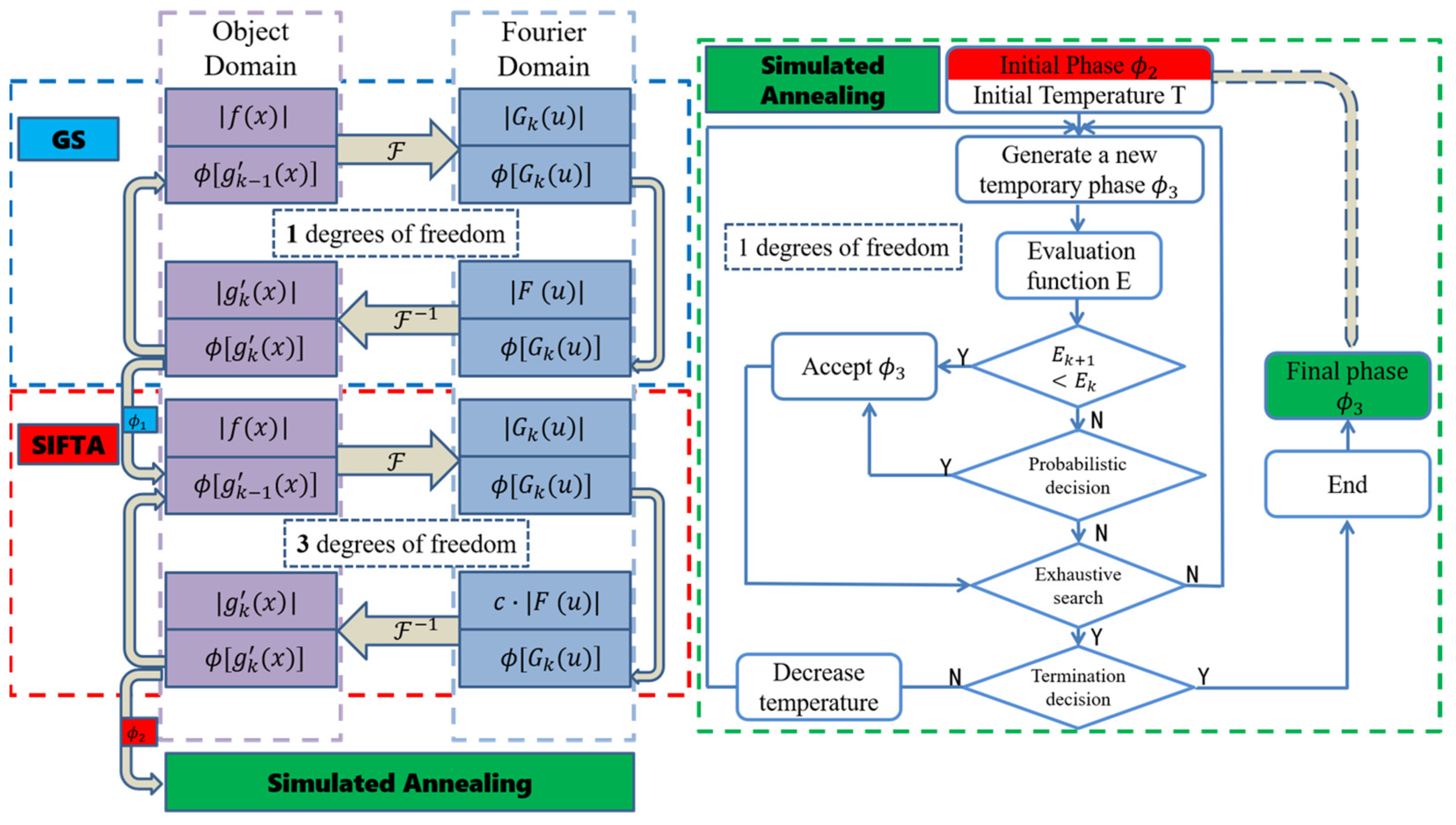
This paper addresses the shortcomings in current beam shaping algorithms and proposes a novel optimization algorithm. The new algorithm combines the advantages of both local and global algorithms, utilizing the results of the GS algorithm and the symmetrical iterative Fourier transform algorithm (SIFTA) [
31] as foundations while introducing SA algorithm for further optimization. Additionally, appropriate zero-padding and phase quantization are incorporated into the algorithm process, making the shaping results more realistic and reliable and minimizing the degradation of the phase hologram as much as possible. The simulation results demonstrate that our algorithm successfully integrates the strengths of both global and local algorithms. It achieves satisfactory shaping results for flat-top super Gaussian beams. Compared to other algorithms, the proposed algorithm achieves an average reduction of 37% in root mean square error and an average reduction of 39% in uniformity error without a significant decrease in diffraction efficiency. This improves the quality and concentration of beam shaping and also indicates the reliability of the phase holograms generated by the algorithm.
3. Simulation Results
This paper demonstrates the reliability of the algorithm by numerically simulating the shaping of a Gaussian beam into a flat-top super-Gaussian beam. The simulation employed a phase only LCOS with 4k resolution from Holoeye to load the phase holograms. The parameters of this LCOS are as follows: pixel size: 3.74 μm, phase delay: 2π (1550 nm), phase level: 256, wavelength range: 1400 nm–1700 nm. To reduce computational load without affecting results, a small number of continuous pixels located on the x-axis are selected as the input region. To enhance the reliability and authenticity of the optimization results, sufficient zero-padding is applied to the phase hologram, resulting in a total of 10,240 sampling points on the x-axis. Furthermore, phase quantization of 256 levels is performed during the process.
After setting the incident beam as a regular Gaussian beam with a wavelength of 1550 nm, its distribution is
, where
is the waist radius of the Gaussian beam. The target beam is a high-order super-Gaussian beam, expressed as
, where
is the waist radius, and n = 40.
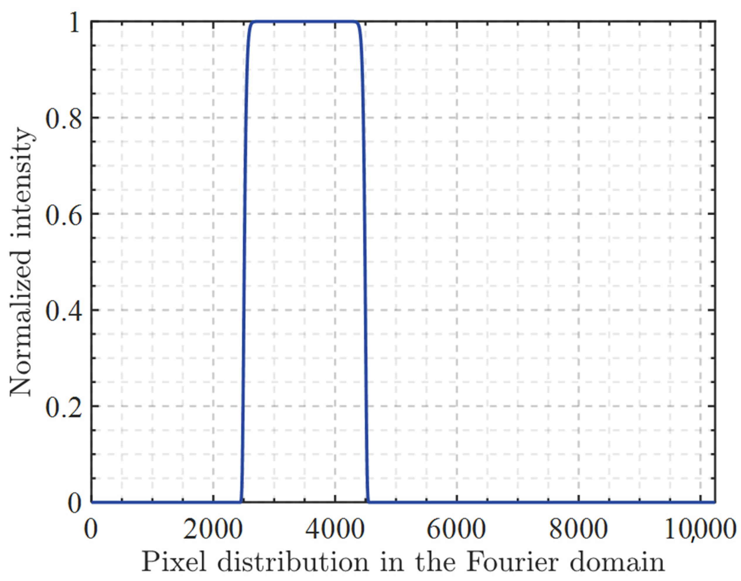
Figure 2 shows the target super-Gaussian beam after normalization. It should be noted that most of the normalized intensity images in this paper are not centered, and this is to indicate the tolerance of the algorithm to beam deflection. Similar to the effects caused by zero-padding and phase quantization, most algorithms tend to degrade the reconstruction quality when the beam undergoes asymmetric deflection.
According to the characteristics of beam shaping, we set diffraction efficiency
η, root mean square error
ε, and the min-to-max uniformity error Δ of the shaping region as the evaluation criteria, corresponding to the energy utilization and shaping capability of beam shaping. The optimization function for the SA algorithm is set as E =
η +
ε.
where
BS represents the beam shaping region,
is the output intensity in the
BS region,
is the actual output intensity,
is the target output intensity, and
is the number of sampling points in the
BS region.
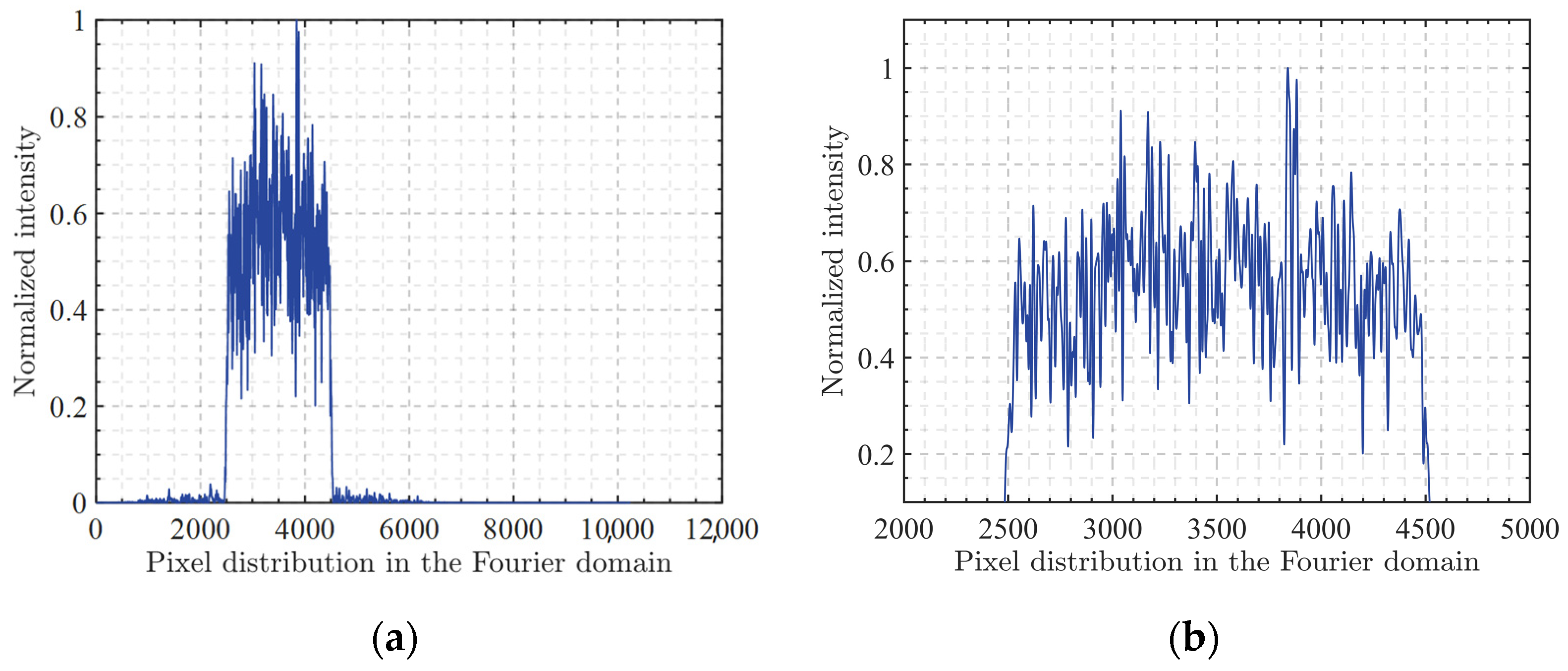
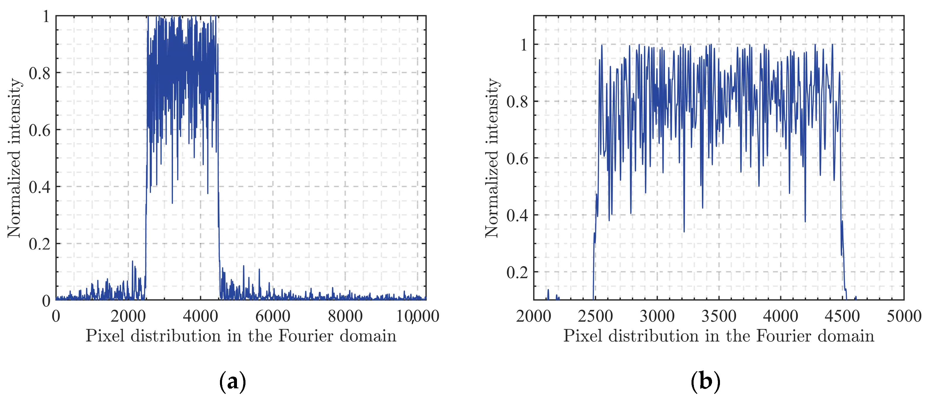
Figure 3 shows the shaping result of the GS algorithm and its locally enlarged view. It is worth noting that both zero-padding and phase quantization were simultaneously applied in this process. The x and y axes represent the distribution of Fourier domain pixels and the normalized intensity, respectively.
Table 1 presents the evaluation metrics for the results of the GS algorithm, the diffraction efficiency, root mean square error and uniformity error are denoted as 98.29%, 0.3901, and 66.54%, respectively. It can be observed that the output beam has a high energy concentration and diffraction efficiency, but the overall shaping effect is poor. It deviates significantly from the target flat-top beam, and the top of the beam is uneven, failing to meet the shaping requirements.
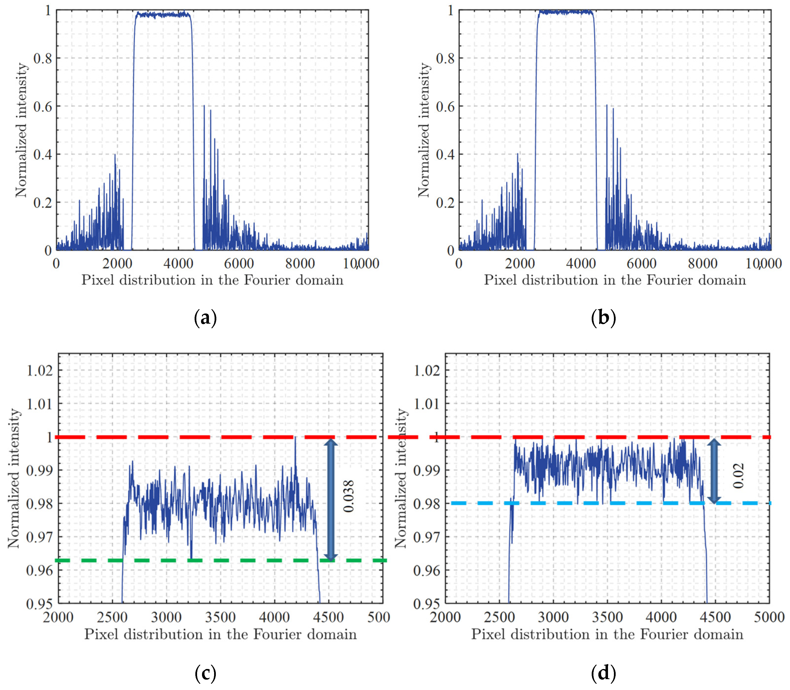
Figure 4 shows the beam shaping results of the SIFTA algorithm and the proposed algorithm. It should be noted again that, similar to the process in
Figure 3, both zero-padding and phase quantization were applied simultaneously in the calculation process of
Figure 4. In fact, these two techniques are pervasive throughout the entire paper. The top part displays the intensity distribution of both algorithms, and the bottom part shows their respective locally enlarged views. The red dashed line represents the highest point of normalized intensity, while the blue and green dashed lines represent the lowest points of intensity for the proposed algorithm and SIFTA algorithm in beam shaping, respectively.
Table 2 presents the evaluation metrics for the results of the SIFTA algorithm and the proposed algorithm; the diffraction efficiency for the SIFTA algorithm and the proposed algorithm is denoted as 87.94% and 87.93%, the root mean square error is 0.0179 and 0.0088, and the uniformity error is 1.91% and 1.02%, respectively.
From the distribution of energy and diffraction efficiency in the images, it can be seen that SIFTA and the proposed algorithm have similar energy concentration, with close energy utilization rates. Compared to the GS algorithm, both of these algorithms exhibit a significant decrease in diffraction efficiency due to the introduction of amplitude freedom. In terms of beam flatness and root mean square error, the proposed algorithm demonstrates stronger beam shaping capabilities, achieving a more uniform flat-top super-Gaussian beam.
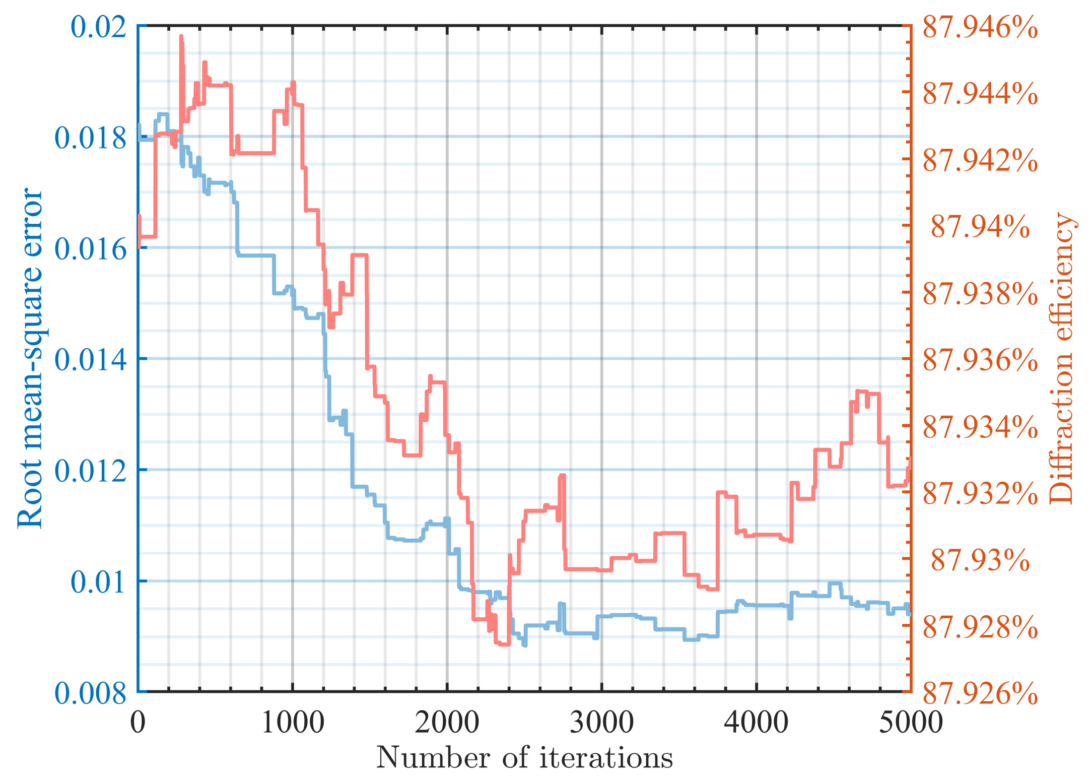
Figure 5 shows the optimization curves of the proposed algorithm. The red curve represents the variation in diffraction efficiency, while the blue curve represents the variation in root mean square error. It can be observed that after many iterations, the diffraction efficiency of the output beam shows almost no significant decrease, and the root mean square error decreases by an order of magnitude, numerically reducing by more than half. This indicates that the proposed algorithm ensures a high energy concentration and provides higher flatness at the top, achieving good results in the flat-top super-Gaussian beam shaping.
To further demonstrate the effectiveness of combining local and global algorithms, an additional control group was set up in this paper. In this set of simulation experiments, we omitted the use of SIFTA and instead optimized the results of the GS algorithm directly using the SA algorithm.
Figure 6a shows the normalized intensity distribution obtained without using the SIFTA algorithm, and
Figure 6b is a local magnification of the signal area.
From
Figure 6, it can be seen that, even without the use of the SIFTA algorithm, the global SA algorithm can still optimize the basic GS algorithm to some extent. Although it may not achieve the same level of effectiveness as our proposed algorithm, the results of this beam shaping process appear more uniform compared to the GS algorithm, and there is no significant energy leakage outside the signal area. This approach is more suitable for applications requiring extremely high energy concentration in beam shaping.
Table 3 presents the data analysis results corresponding to
Figure 5. Compared to the GS algorithm, the combination of GS with GA resulted in a decrease in diffraction efficiency by 4.36%, a reduction in root mean square error by 47.99%, and a decrease in flatness error by 29.38%. This performance is highly promising, as it achieves significant improvement in beam fidelity with only a small sacrifice in energy efficiency.
To further demonstrate the reliability and stability of the proposed algorithm, we conducted additional simulations for validation, as shown in
Table 4, which compares the results of six simulations using the GS algorithm, SIFTA algorithm, and the proposed algorithm. Simultaneously, we calculated the averages of the six datasets. In terms of energy concentration, the GS algorithm exhibits the highest diffraction efficiency at 98.57%, while there is little difference between the SIFTA algorithm and the proposed algorithm. In terms of top flatness, the proposed algorithm achieves the best shaping effect, with an average root mean square error of 0.0086 that is two orders of magnitude lower compared to the basic GS algorithm and nearly 37% lower compared to the SIFTA algorithm. The uniformity error is reduced by nearly 39%.
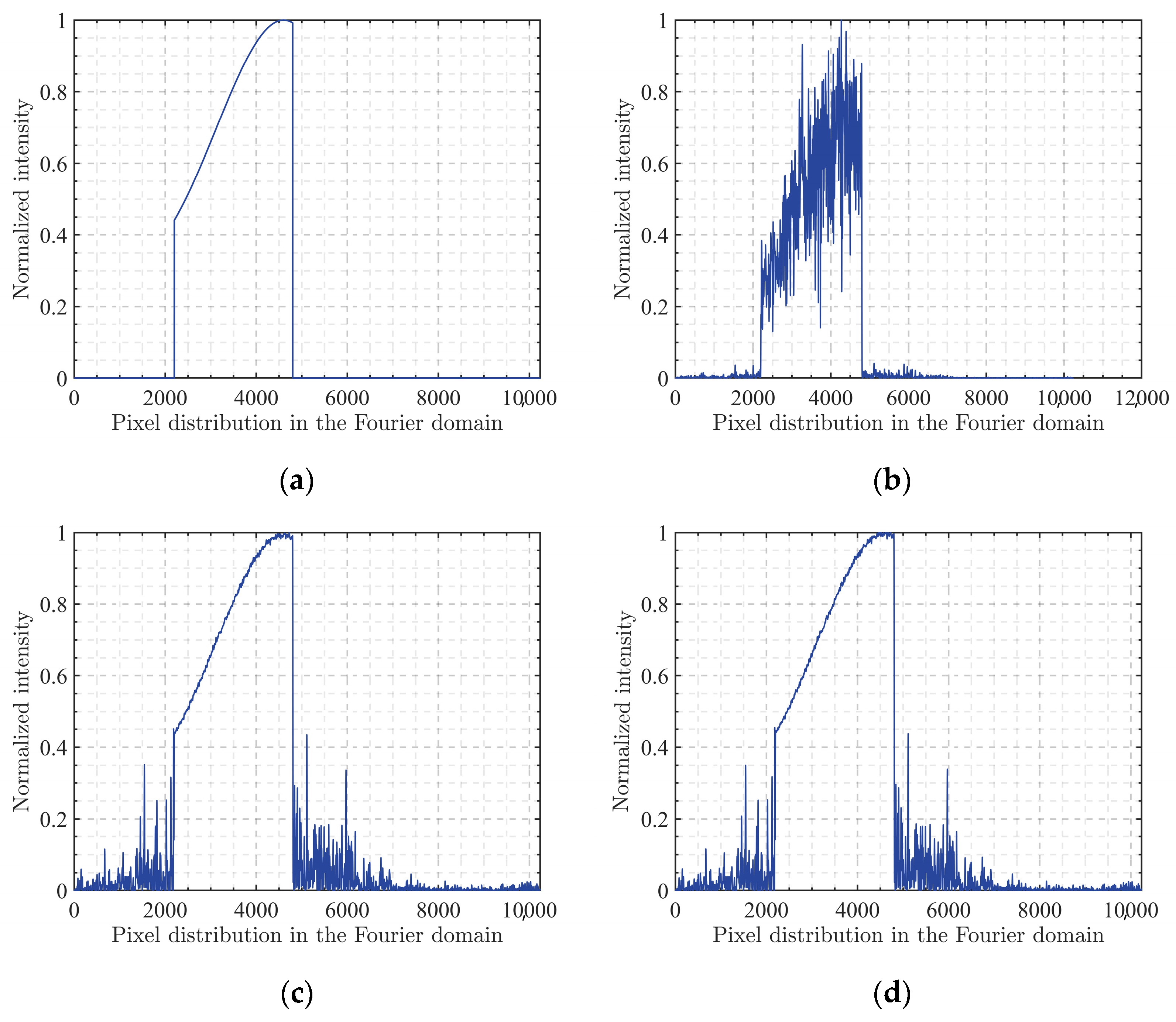
Additionally, to further validate the algorithm’s universality, this paper included various non-flat-top beams as supplements to explore the applicability of the algorithm in other cases of beam shaping. The overall process remained essentially consistent with the previous simulations, with appropriate zero-padding and phase quantization introduced as before and the target beam profile replaced by a localized sine distribution. The normalized intensity distributions are shown in
Figure 7, where
Figure 7a represents the target output intensity,
Figure 7b shows the optimization result of the GS algorithm,
Figure 7c presents the optimization result of the SIFTA algorithm, and
Figure 7d displays the optimization result of the algorithm proposed in this paper. It can be observed that the GS algorithm only achieves output at specified positions with very high energy efficiency, but the shaped beam does not exhibit satisfactory shaping effects, showing relatively low fidelity. Both the SIFTA algorithm and the proposed algorithm exhibit excellent optimization performance, with some energy leakage outside the signal region, which reduces the energy utilization efficiency. However, within the signal region, the output beam profile closely matches the target profile, showing high fidelity. Additionally, it is worth noting that, since the SIFTA algorithm has already achieved a small root mean square error, the advanced optimization effect of the proposed algorithm is not clearly visible from
Figure 7 alone. The following data will provide deeper insights, and analysis will demonstrate that this improvement indeed exists.
Table 5 presents the simulation data results for the non-flat-top beam shaping. From the analysis of the data in the table, it can be observed that the GS algorithm exhibits the highest energy efficiency, while the proposed algorithm demonstrates the smallest root mean square error. Compared to the SIFTA algorithm, although the optimization effect may not be visually evident from
Figure 7, the data indicate that the proposed algorithm indeed achieves further overall optimization; the root mean square error decreased by nearly one-third with the proposed algorithm without significantly reducing the diffraction efficiency.
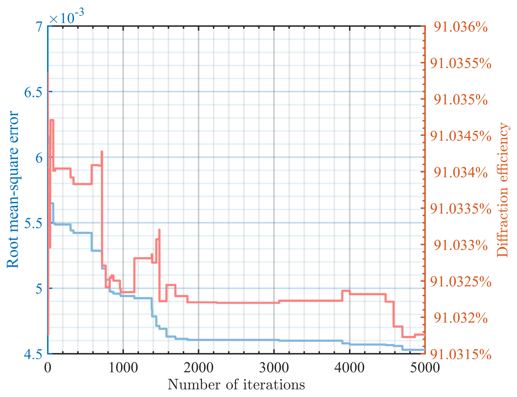
Figure 8 depicts the optimization curve of the proposed algorithm in this simulation. From
Figure 8, it can be observed that the proposed algorithm can maintain the original diffraction efficiency to a large extent during optimization, and there is still a certain downward trend after 5000 iterations of optimization. These conclusions are consistent with those obtained in the previous simulations of flat-top beams in this paper, which, to some extent, demonstrate the generality of the proposed algorithm. It indicates the potential of combining the local algorithm based on IFTA with the global SA algorithm, as their integration can lead to further optimization effects.
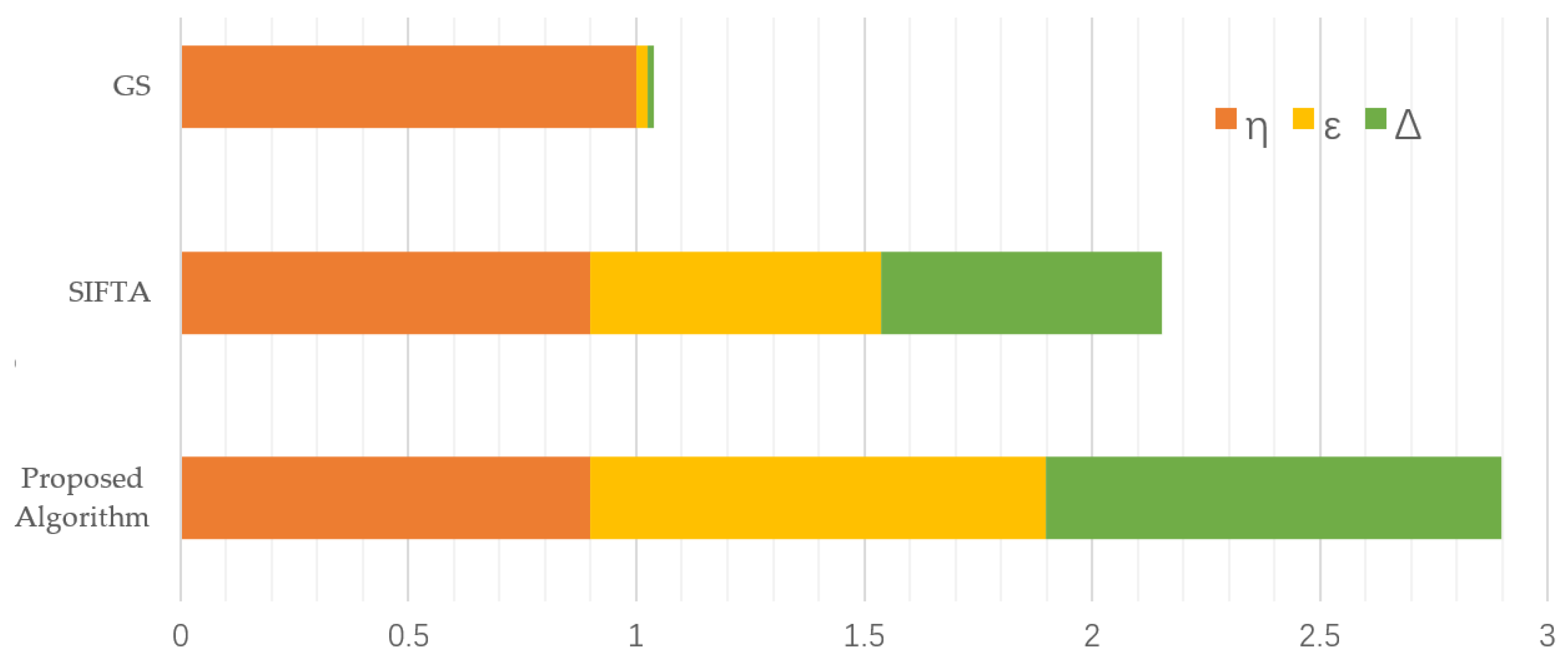
Figure 9 presents a chart based on the average results, normalizing diffraction efficiency with the results of the GS algorithm as the baseline and normalizing root mean square error and uniformity error with the results of the proposed algorithm as the baseline. The total length represents the algorithm’s performance. It can be observed that the proposed algorithm is more suitable for beam shaping.
4. Discussion and Conclusions
We propose a segmented beam shaping optimization algorithm that combines local and global optimization techniques. The algorithm comprises three components: the GS algorithm for initial solutions, the SIFTA algorithm for intermediate optimization, and the SA algorithm for final optimization. By integrating these algorithms, we aim to harness the strengths of both local and global approaches, creating a fast, efficient, and accurate beam shaping optimization algorithm.
In addition to the unique structure and optimization strategy, our paper stands out from many phase retrieval studies by simultaneously considering zero-padding and phase quantization. Unlike some algorithm papers that only focus on low-resolution scenarios without sufficient zero-padding and proper phase quantization according to device requirements, our approach enhances the reliability and practicality of phase holograms. Proper zero-padding increases the resolution and clarity of phase holograms, revealing hidden speckles in the image. Introducing zero-padding into the algorithm workflow allows flaws hidden in the image to participate in the optimization process, thereby reducing artifacts and blurring in image reconstruction and improving the quality and visualization of phase holograms. Moreover, since current LCOS devices have limited grayscale levels, phase quantization is necessary before loading phase holograms. However, this limited discretization introduces quantization noise, leading to reduced image resolution and fidelity and causing discrepancies between experimental and simulated results. Introducing phase quantization in the algorithm workflow enables noise to participate in optimization. By setting appropriate step sizes in the SA algorithm to match the grayscale, the negative effects of phase quantization can be minimized.
The reliability and universality of the algorithm are verified through several sets of simulation experiments. Specifically, in shaping flat-top super-Gaussian beams, this algorithm performs well. Compared to the SIFTA algorithm, it achieves an average reduction of nearly 37% in root mean square error and 39% in uniformity error while maintaining energy efficiency. Compared to the basic GS algorithm, the algorithm achieves an average reduction of nearly 10% in diffraction efficiency, a reduction of two orders of magnitude in root mean square error, and a reduction of over 66% in uniformity error. Additionally, a simulation experiment using only the GS and GA algorithms was conducted. Compared to the GS algorithm, this algorithm achieves a 4.36% reduction in diffraction efficiency, a 47.99% reduction in root mean square error, and a 29.38% reduction in uniformity error. The simulation performance of shaping flat-top beams illustrates the correctness of the optimization approach adopted in this paper. The quality of the beams is effectively improved whether using one or both of the pre-optimization algorithms. Furthermore, the effectiveness of the pre-optimization algorithms determines the upper and lower bounds of the overall algorithm performance. When only the GS algorithm is used, although there is significant optimization potential, the final results may not reach a high level. However, with the addition of SIFTA, further optimization is possible, indicating the critical role of advanced algorithms and providing new insights for future research directions.
As a supplement to the algorithm’s universality, a set of simulation experiments on non-flat-top beams was conducted. In this experiment, the algorithm still achieved similar optimization results. Compared to the SIFTA algorithm, the diffraction efficiency was almost unchanged, but the root means square error decreased by 30.77%, with a downward trend even after 5000 optimizations. This partly demonstrates the algorithm’s universality and stability.
It is worth discussing the fact that the idea of combining multiple algorithms is not a recent development. In the referenced literature mentioned earlier, examples of such combinations can be found. For instance, in a paper published by Ping Su et al. [
25] in 2020, they combined two global optimization algorithms, particle swarm optimization and simulated annealing, for designing optical diffractive elements. In this approach, the SA algorithm is employed as a pre-optimization step, while the particle swarm optimization (PSO) algorithm serves as a post-optimization step to reduce perturbations and escape local minima, thereby seeking the global optimum solution. The effectiveness of the algorithm is demonstrated through simulations, utilizing a pixel area of 256 ∗ 256 for beam shaping, with a rectangular shape of 282 ∗ 150 selected as the shaping profile. In addition to the SA-PSO algorithm, two control groups are set up in the simulations: the SA algorithm and GS algorithm. Ultimately, the GS algorithm takes 20 s, the SA algorithm takes 15 min, and the SA-PSO algorithm takes 1 h. In terms of results, compared to the GS algorithm, the SA-PSO algorithm successfully improves shaping accuracy and enhances beam uniformity by over 10%. From the perspective of this paper, the significant time investment required for computation warrants consideration, especially considering that the overall improvement of this algorithm compared to the basic GS algorithm is just over 10%. Furthermore, similar to many other studies, this paper also does not consider the negative impacts of zero-padding and phase quantization; hence, the 10% improvement obtained is questionable. As a more efficient alternative, the GS-SA algorithm utilized in this paper can achieve better shaping results and faster speeds. However, many of these combined algorithms did not delve into the use of zero-padding and phase quantization for in-depth exploration, nor did they seek advanced local algorithms to enhance overall optimization limits. Consequently, the improvements brought by such approaches may be unreliable, potentially leading to mismatches between simulation and experimental results. Additionally, the beam shaping effects of these algorithms may be unstable and low in precision. Nevertheless, on the other hand, this provides insights for the development of new algorithms in the future.
In our future work, we will explore the following aspects: 1., improving the tolerance of our algorithm to phase disturbances; 2., attempting to integrate other optimization algorithms and broaden their application scenarios; and 3., enhancing the simulated annealing algorithm and introducing amplitude freedom.
In conclusion, this paper proposes a novel segmented beam shaping optimization algorithm that successfully combines the advantages of local and global algorithms, while considering the negative effects of zero-padding and phase quantization during the optimization process. The algorithm’s universality and reliability are demonstrated through multiple simulations of shaping flat-top and non-flat-top beams.
