Multispectral Narrowband Frustrated Total Internal Reflection Filter with Inclusions of Plasmonic Nanoparticles


Abstract
1. Introduction
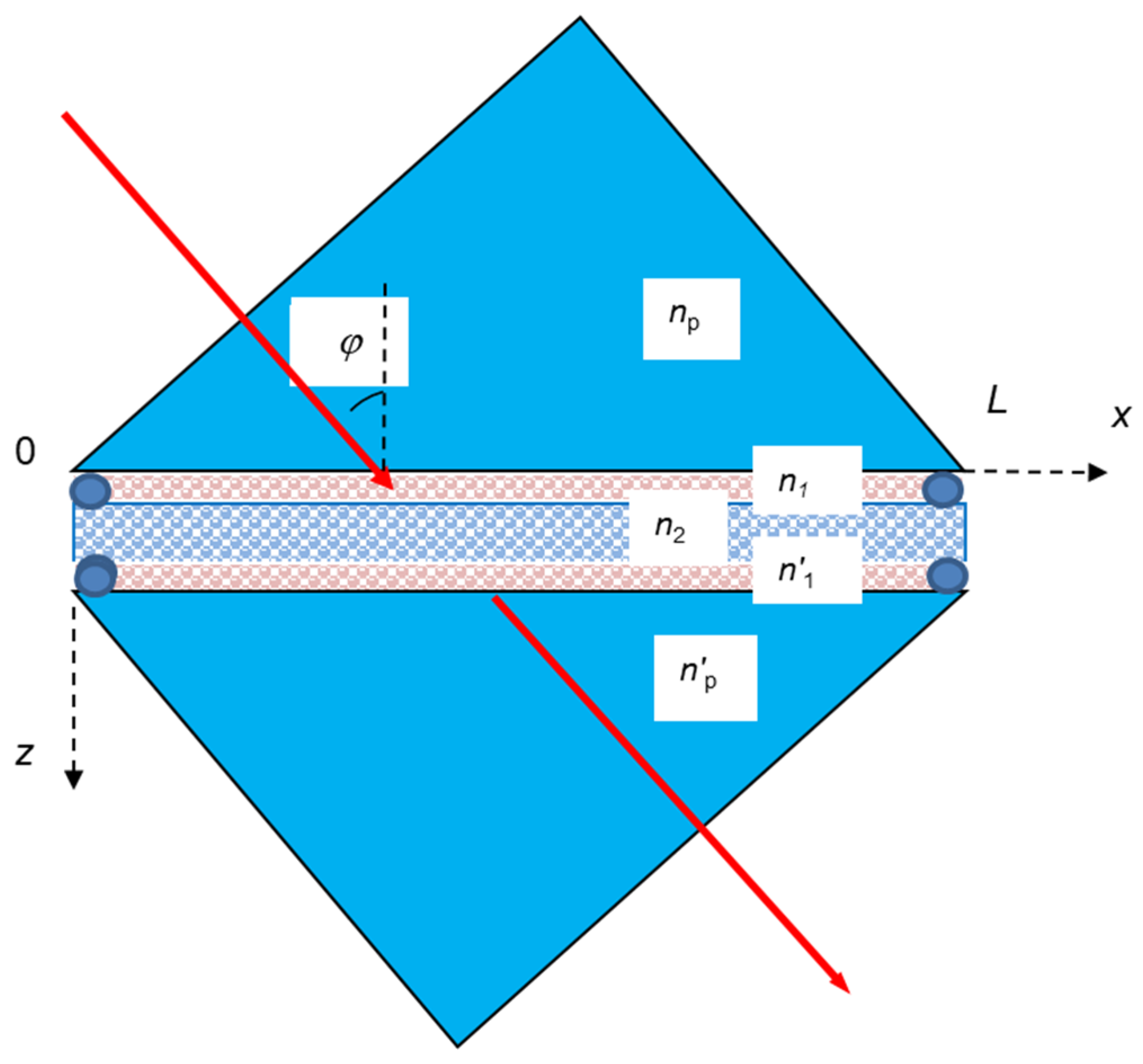
2. FTIR Filter
2.1. Resonance Condition
2.2. Transmittance
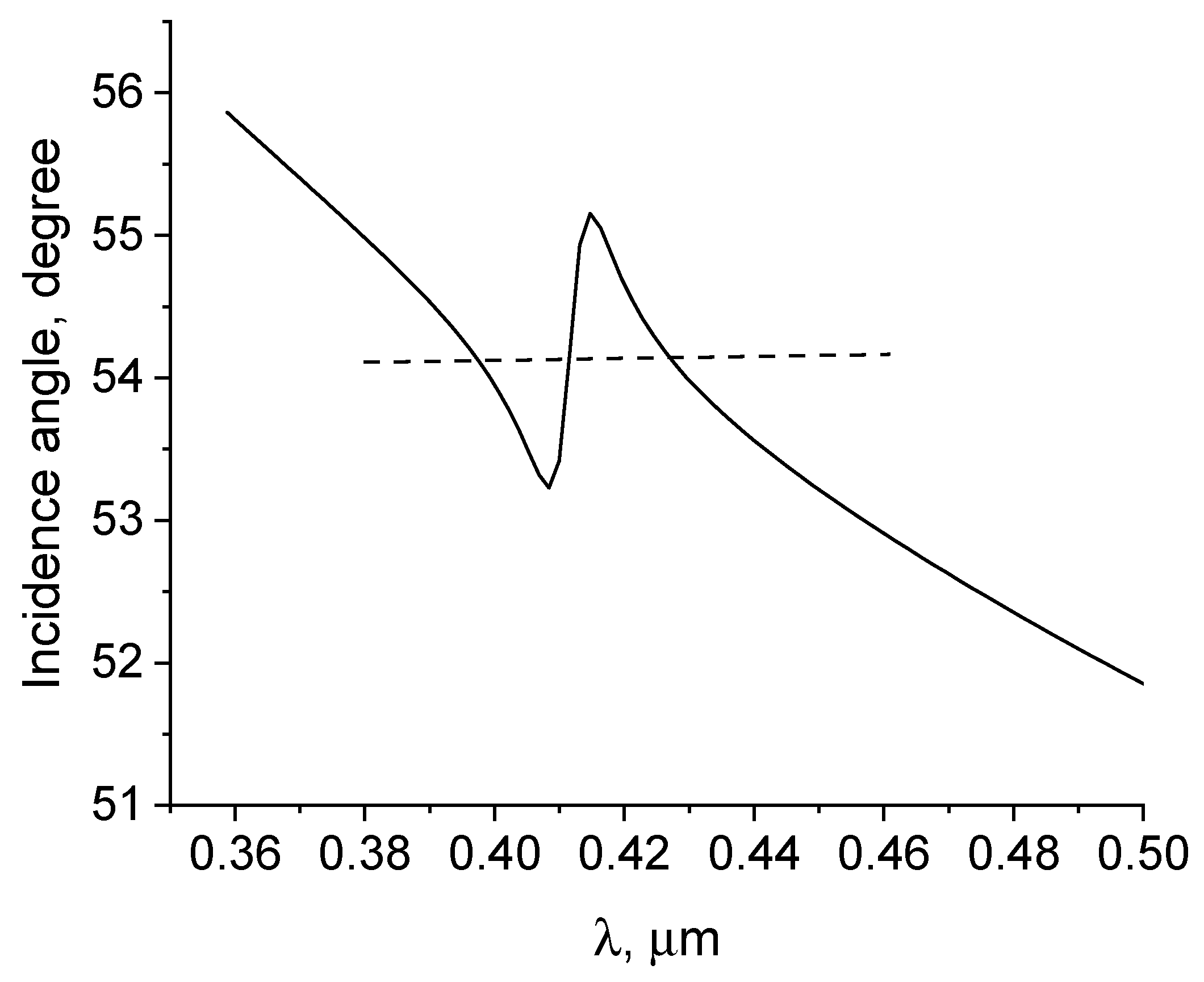
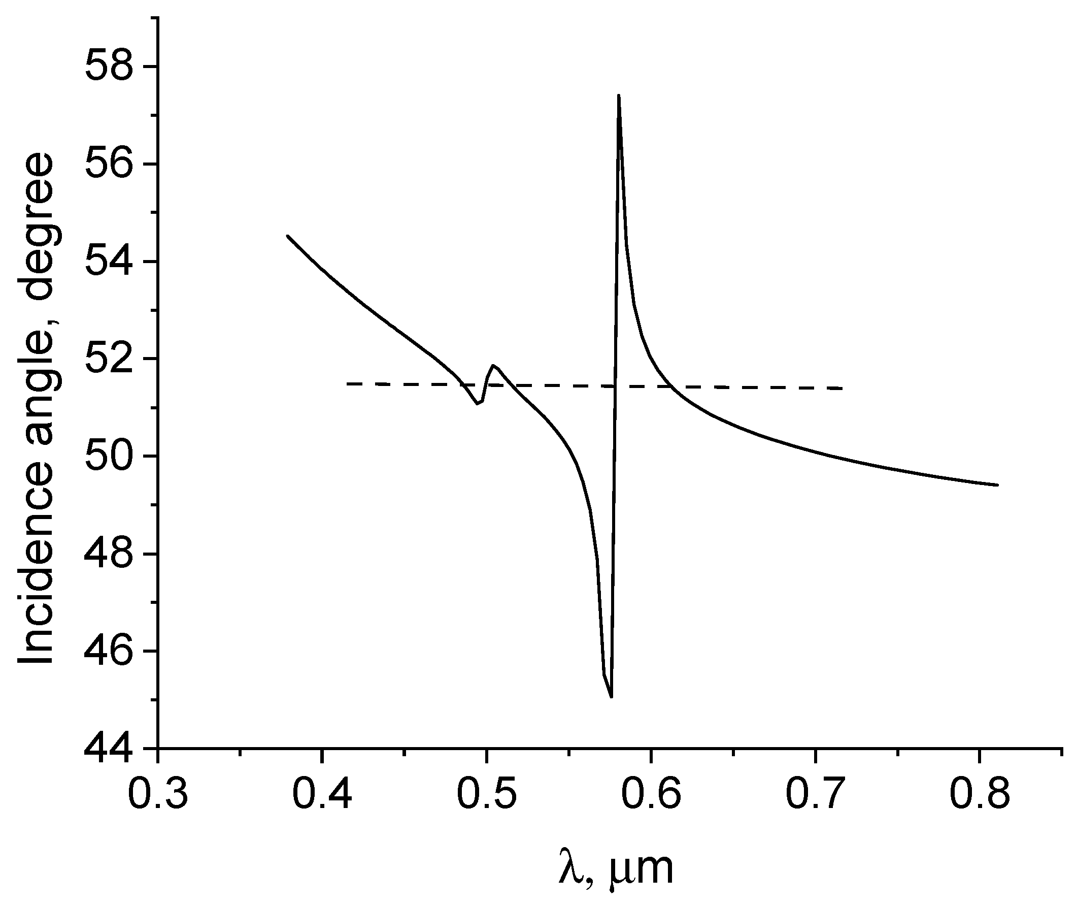
2.3. Dependence of Resonance Incidence Angle on Frequency
Plasmon Resonance in Metal Nanoparticles
3. Simulation Results
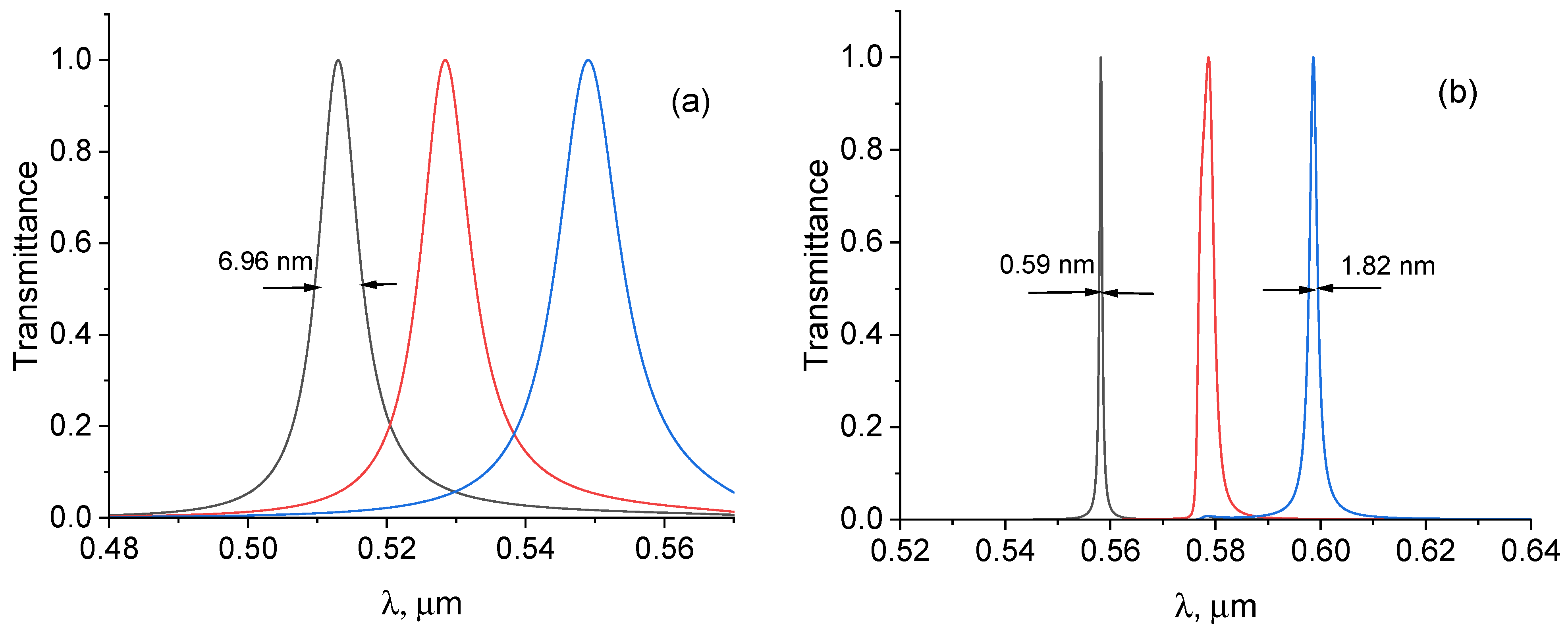
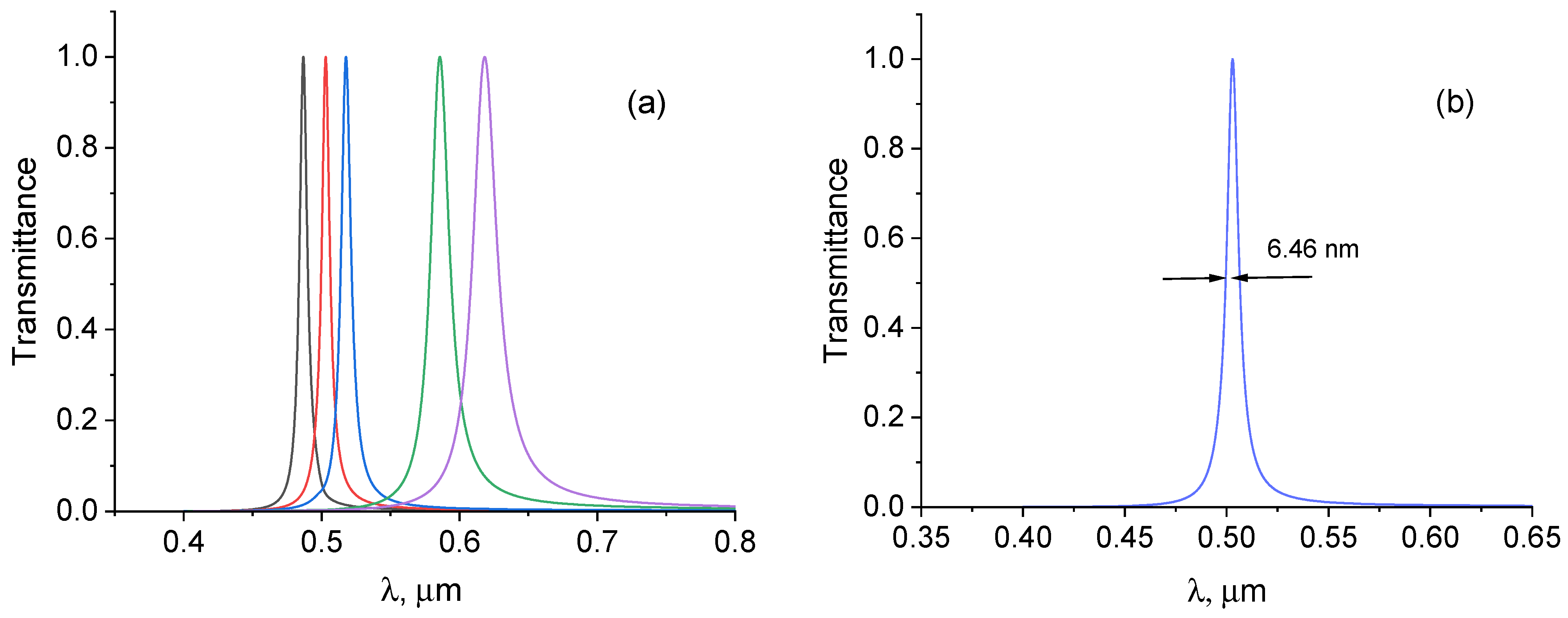
3.1. s-Polarization
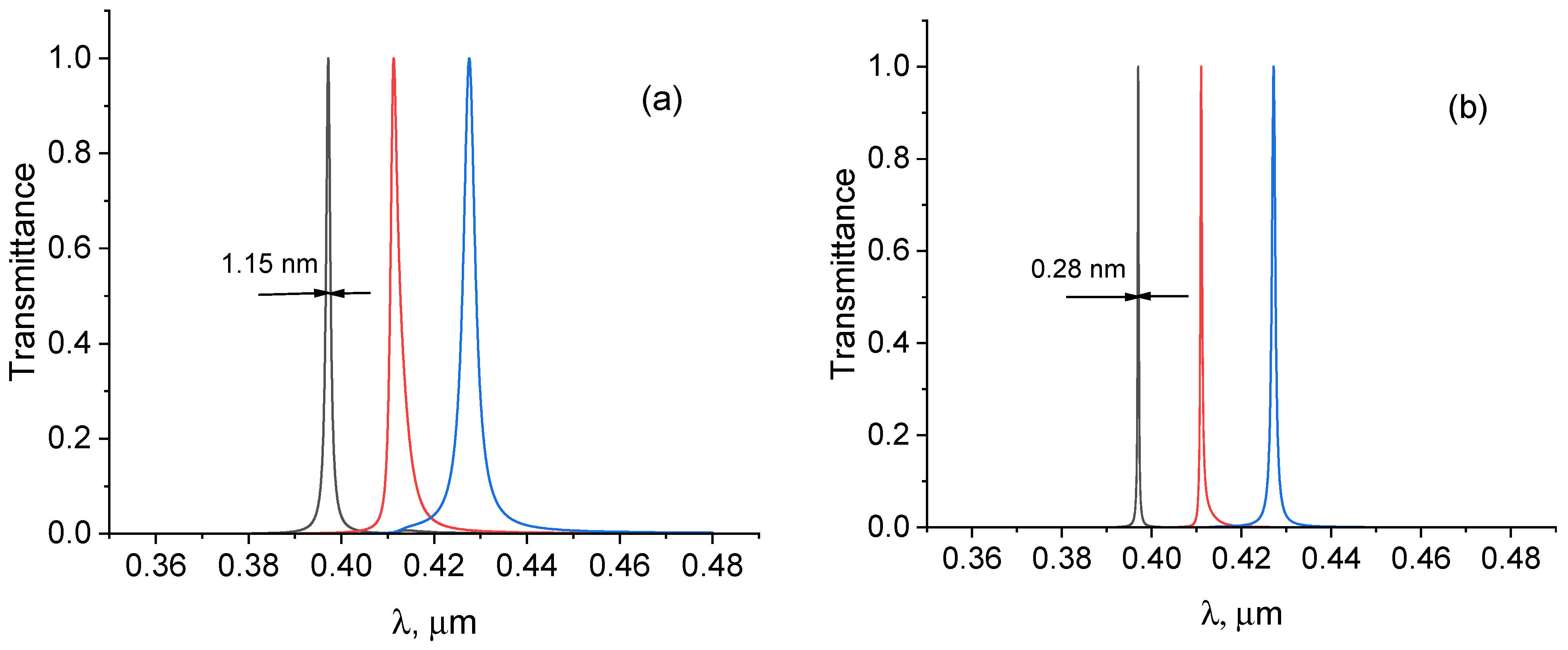
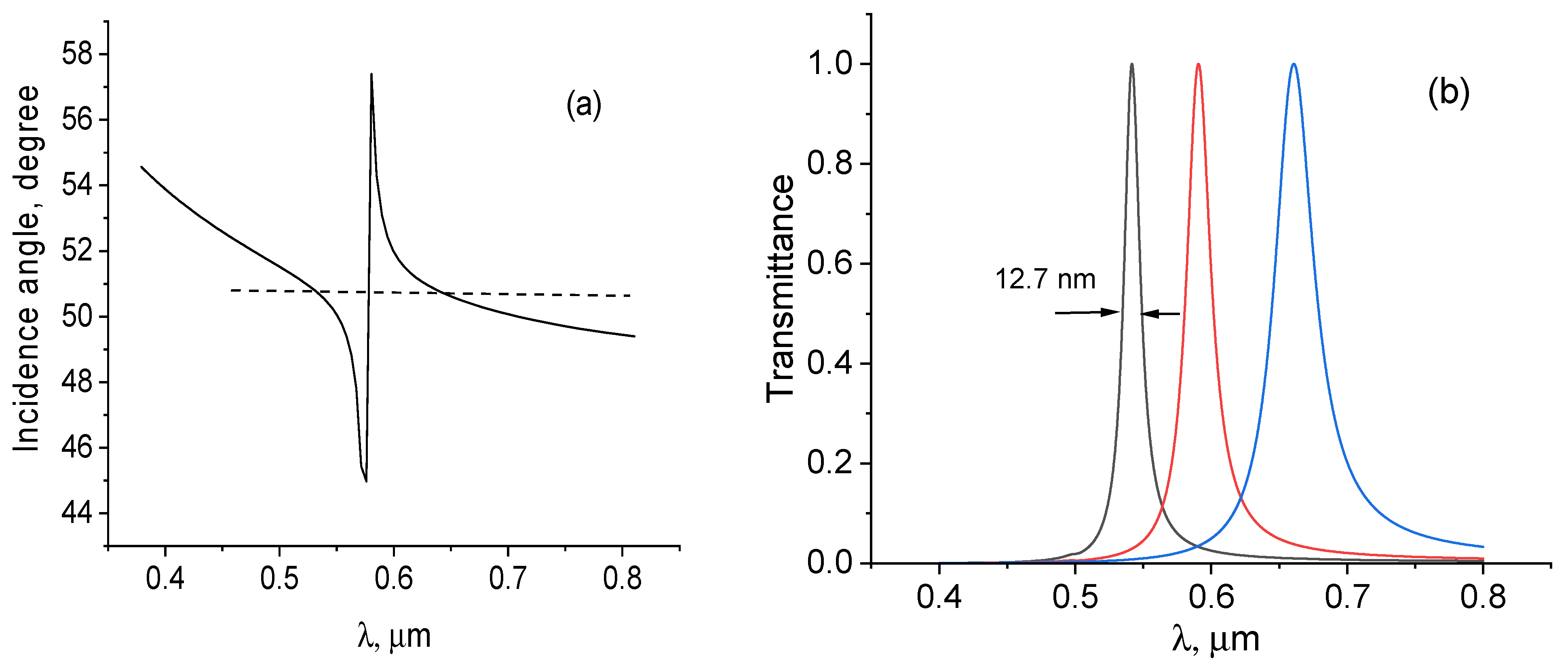
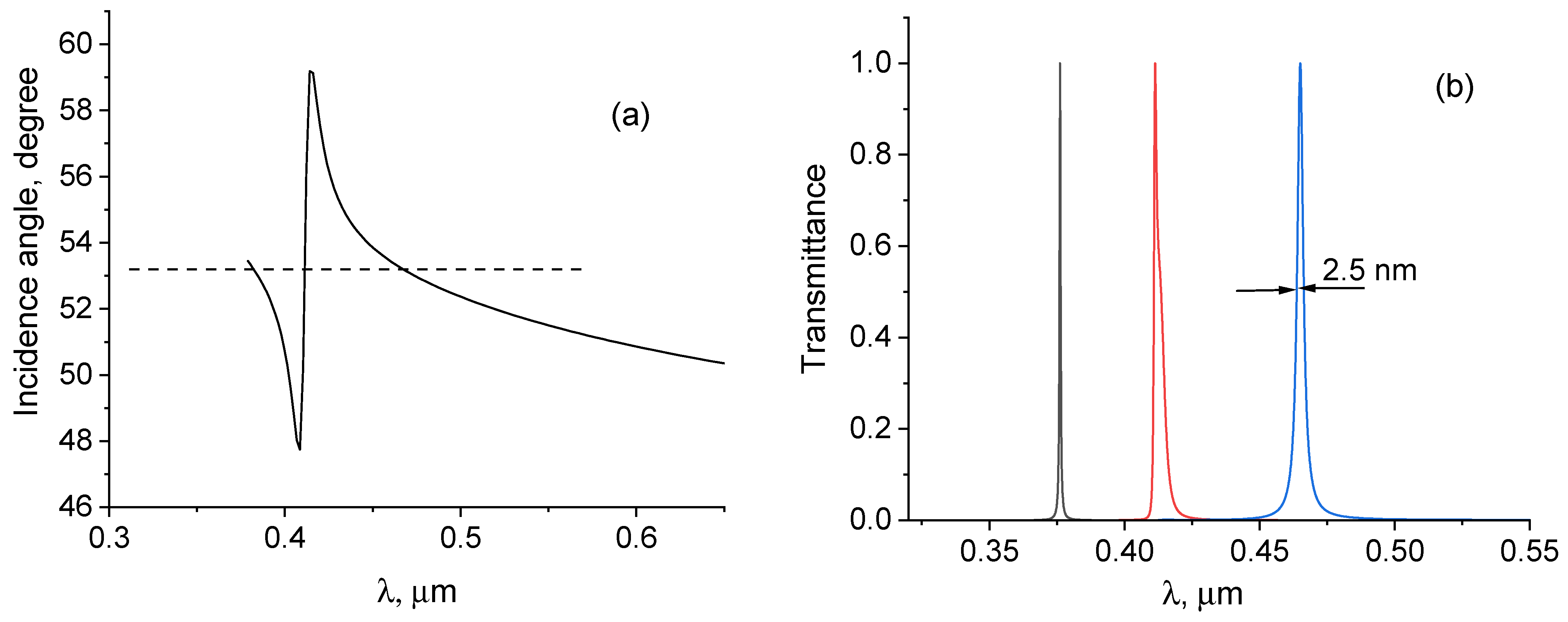
3.2. p-Polarization
4. Discussion
5. Conclusions
Funding
Institutional Review Board Statement
Informed Consent Statement
Data Availability Statement
Conflicts of Interest
References
- Leurgens, P.; Turner, A.F. Frustrated total reflection interference filters. J. Opt. Soc. Am. 1947, 37, 983. [Google Scholar]
- Iogansen, L.V. Resonance diffraction of waves in lamellar inhomogeneous media. Sov. Phys. JETP 1961, 13, 1291–1295. [Google Scholar]
- Bergstein, L.; Shulman, C. The Frustrated total reflection filter. I. Spectral analysis. Appl. Opt. 1966, 5, 9–21. [Google Scholar] [CrossRef] [PubMed]
- Ulrich, R. Theory of the prism–film coupler by plane-wave analysis. J. Opt. Soc. Am. 1970, 60, 1337–1350. [Google Scholar] [CrossRef]
- Zhu, S.; Yu, A.W.; Hawley, D.; Roy, R. Frustrated Total Internal Reflection: A Demonstration and Review. Am. J. Phys. 1986, 54, 601–607. [Google Scholar] [CrossRef]
- Azzam, R.M.A.; De, A. Circular polarization beam splitter that uses frustrated total internal reflection by an embedded symmetric achiral multilayer coating. Opt. Lett. 2003, 28, 355–357. [Google Scholar] [CrossRef] [PubMed]
- Li, L.; Dobrowolski, J.A. Optical coatings with an integral FTIR air layer. Opt. Express 2010, 18, 3784–3792. [Google Scholar] [CrossRef]
- Nguen, V.B.; Gubanova, L.A.; Bui, D.B. Features of the spectral characteristics of narrow-band optical filters with oblique incidence of the radiation beam. Tech. Phys. Lett. 2019, 45, 430–432. [Google Scholar] [CrossRef]
- Petrov, N.I. Frustrated-total-internal-reflection-based thin-film color separator. Opt. Lett. 2007, 32, 2744–2746. [Google Scholar] [CrossRef]
- Farmani, A.; Miri, M.; Sheikhi, M.H. Tunable resonant Goos–Hänchen and Imbert–Fedorov shifts in total reflection of terahertz beams from graphene plasmonic metasurfaces. J. Opt. Soc. Am. B 2017, 34, 1097–1106. [Google Scholar] [CrossRef]
- Bocharov, A.A. Goos-Hänchen shift of a transmitted light beam in frustrated total internal reflection for moderately large gap widths. Opt. Commun. 2017, 389, 297–302. [Google Scholar] [CrossRef]
- Xiang, L.; Liu, W.; Wei, Z.; Meng, H.; Liu, H.; Guo, J.; Zhi, Y.; Huang, Z.; Li, H.; Wang, F. Strong enhancement of Goos–Hänchen shift through the resonant optical tunneling effect. Opt. Express 2022, 30, 47338–47349. [Google Scholar] [CrossRef] [PubMed]
- Petrov, N.I.; Sokolov, Y.M.; Stoiakin, V.V.; Danilov, V.A.; Popov, V.V.; Usievich, B.A. Observation of Giant Angular Goos-Hanchen Shifts Enhanced by Surface Plasmon Resonance in Subwavelength Grating. Photonics 2023, 10, 180. [Google Scholar] [CrossRef]
- Fedchenko, D.P.; Kim, P.N.; Timofeev, I.V. Photonic Topological Insulator Based on Frustrated Total Internal Reflection in Array of Coupled Prism Resonators. Symmetry 2022, 14, 2673. [Google Scholar] [CrossRef]
- Bocharov, A.A. Goos–Hänchen shift of a light beam tunable by graphene in the resonant optical tunneling structure. J. Opt. 2022, 24, 115606. [Google Scholar] [CrossRef]
- Petrov, N.I. Splitting the bandwidth of a frustrated total internal reflection filter with nanoparticle inclusions. OSA Cont. 2020, 3, 2591–2601. [Google Scholar] [CrossRef]
- Kelly, K.L.; Coronado, E.; Zhao, L.L.; Schatz, G.C. The optical properties of metal nanoparticles: The influence of size, shape, and dielectric environment. J. Phys. Chem. 2003, 107, 668–677. [Google Scholar] [CrossRef]
- Kreibig, U.; Vollmer, M. Optical Properties of Metal Clusters; Springer: Berlin/Heidelberg, Germany, 1995. [Google Scholar]
- Cai, W.; Shalaev, V. Optical Metamaterials: Fundamentals and Applications; Springer: Berlin/Heidelberg, Germany, 2010. [Google Scholar]
- Johnson, P.B.; Christy, R.W. Optical constants of the noble metals. Phys. Rev. B 1972, 6, 4370–4379. [Google Scholar] [CrossRef]
- Spanier, J.E.; Herman, I.P. Use of hybrid phenomenological and statistical effective-medium theories of dielectric functions to model the infrared reflectance of porous SiC films. Phys. Rev. B 2000, 61, 10437. [Google Scholar] [CrossRef]
- Petrov, N.I.; Pustovoit, V.I. Acousto-optical properties of heterogeneous media with a nonuniform distribution of nanoparticles. JETP Lett. 2019, 109, 18–23. [Google Scholar] [CrossRef]
- Khlebtsov, N.G. Optics and biophotonics of nanoparticles with a plasmon resonance. Quantum Electron. 2008, 38, 504–529. [Google Scholar] [CrossRef]
- Moiseev, S.G.; Ostatochnikov, V.A. Defect modes of one-dimensional photonic-crystal structure with a resonance nanocomposite layer. Quantum Electron. 2016, 46, 743–748. [Google Scholar] [CrossRef]
- Petrov, N.I.; Pustovoit, V.I. Small-Sized Interferometer with Fabry-Perot Resonators for Gravitational Wave Detection. Sensors 2021, 21, 1877. [Google Scholar] [CrossRef] [PubMed]
- Isaacs, S.; Placido, F.; Abdulhalim, I. Investigation of liquid crystal Fabry-Perot tunable filters: Design, fabrication, and polarization independence. Appl. Opt. 2014, 53, H91–H101. [Google Scholar] [CrossRef] [PubMed]
- Jose, J. Photonic bandgap structure with plasmonic inclusions for refractive index sensing in optofluidics at terahertz frequencies. Opt. Lett. 2017, 42, 470–473. [Google Scholar] [CrossRef] [PubMed]
- Liang, Y.; Lin, H.; Lin, S.; Wu, J.; Li, W.; Meng, F.; Yang, Y.; Huang, X.; Jia, B.; Kivshar, Y. Hybrid anisotropic plasmonic metasurfaces with multiple resonances of focused light beams. Nano Lett. 2021, 21, 8917–8923. [Google Scholar] [CrossRef] [PubMed]
- Li, Y.; Zhou, Y.; Liu, Q.; Lu, Z.; Luo, X.-Q.; Liu, W.-M.; Wang, X.-L. Multi-Wavelength Selective and Broadband Near-Infrared Plasmonic Switches in Anisotropic Plasmonic Metasurfaces. Nanomaterials 2023, 13, 3141. [Google Scholar] [CrossRef]
- Dorrah, A.H.; Capasso, F. Tunable structured light with flat optics. Science 2022, 376, 367. [Google Scholar] [CrossRef] [PubMed]
- Li, G.; Zhang, S.; Zentgraf, T. Nonlinear photonic metasurfaces. Nat. Rev. Mater. 2017, 2, 17010. [Google Scholar] [CrossRef]
- Pertsch, T.; Kivshar, Y. Nonlinear optics with resonant metasurfaces. MRS Bull. 2020, 45, 210–220. [Google Scholar] [CrossRef]
- Krasnok, A.; Tymchenko, M.; Alu, A. Nonlinear metasurfaces: A paradigm shift in nonlinear optics. Mater. Today 2018, 21, 8–21. [Google Scholar] [CrossRef]
- Vabishchevich, P.; Kivshar, Y. Nonlinear photonics with metasurfaces. Phot. Res. 2023, 11, 850–864. [Google Scholar] [CrossRef]
- Liu, Z.X.; You, C.; Wang, B.; Wu, Y. Nanoparticle-mediated chiral light chaos based on non-Hermitian mode coupling. Nanoscale 2020, 12, 2118–2125. [Google Scholar] [CrossRef]
- Peng, J.X.; Jin, C.; Jin, L.; Liu, Z.X. Quantum Coherence Regulated by Nanoparticles in a Whispering-Gallery-Mode Microresonator. Ann. Phys. 2021, 533, 2100210. [Google Scholar] [CrossRef]
- Chen, J.; Ban, Y.; Zhu, Q.B.; Chen, X. Graphene-assisted resonant transmission and enhanced Goos–Hänchen shift in a frustrated total internal reflection configuration. Opt. Lett. 2016, 41, 4468–4471. [Google Scholar] [CrossRef]
- Tran, T.Q.; Lee, S.; Heo, H.; Kim, S. Tunable Wide-Angle Tunneling in Graphene-Assisted Frustrated Total Internal Reflection. Sci. Rep. 2016, 6, 19975. [Google Scholar] [CrossRef]
- Petrov, N.I. Depolarization of Light in Optical Fibers: Effects of Diffraction and Spin-Orbit Interaction. Fibers 2021, 9, 34. [Google Scholar] [CrossRef]
- Petrov, N.I. Sharp focusing of partially coherent Bessel-correlated beams by a graded-index lens. Opt. Lett. 2023, 48, 6048–6051. [Google Scholar] [CrossRef]


Disclaimer/Publisher’s Note: The statements, opinions and data contained in all publications are solely those of the individual author(s) and contributor(s) and not of MDPI and/or the editor(s). MDPI and/or the editor(s) disclaim responsibility for any injury to people or property resulting from any ideas, methods, instructions or products referred to in the content. |
© 2024 by the author. Licensee MDPI, Basel, Switzerland. This article is an open access article distributed under the terms and conditions of the Creative Commons Attribution (CC BY) license (https://creativecommons.org/licenses/by/4.0/).
Share and Cite
Petrov, N.I. Multispectral Narrowband Frustrated Total Internal Reflection Filter with Inclusions of Plasmonic Nanoparticles. Photonics 2024, 11, 180. https://doi.org/10.3390/photonics11020180
Petrov NI. Multispectral Narrowband Frustrated Total Internal Reflection Filter with Inclusions of Plasmonic Nanoparticles. Photonics. 2024; 11(2):180. https://doi.org/10.3390/photonics11020180
Chicago/Turabian StylePetrov, Nikolai I. 2024. "Multispectral Narrowband Frustrated Total Internal Reflection Filter with Inclusions of Plasmonic Nanoparticles" Photonics 11, no. 2: 180. https://doi.org/10.3390/photonics11020180
APA StylePetrov, N. I. (2024). Multispectral Narrowband Frustrated Total Internal Reflection Filter with Inclusions of Plasmonic Nanoparticles. Photonics, 11(2), 180. https://doi.org/10.3390/photonics11020180