1. Introduction
In modern optics, much attention is paid to effects of Spin–Orbital Conversion and the spin Hall effect. These fundamental and universal effects describe how a circularly polarized light reflected or passed through a gradient (inhomogeneous) media acquires a transverse shift [
1,
2]. If a light beam with right-handed circular polarization, which has a positive spin angular momentum (SAM), passes through a q-plate [
3] or through an element with a metasurface [
4], then an optical vortex with the left-handed circular polarization, which has an orbital angular momentum (OAM), appears at the output. Many other optical effects, for example, the effect of “optical wheels” [
5], the optical Magnus effect [
6], and the magnetization effect [
7] are associated with this phenomenon. The optical Hall effect was first discovered in 2007 [
8]. In [
8], a light beam with linear polarization passed through a multilayer microcavity formed a beam in the far diffraction zone. This beam had regions with left and right elliptical polarization at the edges. The transformation of a light beam with initial linear polarization into a beam in which light distribution has regions with different spins, that is, regions with left and right circular polarization, is called the spin Hall effect [
9]. The optical Hall effect was observed during reflection from a media interface [
10], during passing through multilayer structures [
11] and metasurfaces [
12,
13], as well as at the focus of a spherical lens [
14].
Some authors reported using the metasurfaces to divide a light beam into different polarization states, OAM-modes or wavelengths. A TiO-film-based metasurface made up of an array of rectangular rods intended to spatially separate an incident 532vnm wave into 4 × 4 diffraction orders with different polarization states has been designed [
15]. A metasurface comprised of rectangular rods with varying heights and orientations (aspect ratio of 15) has been created using 3D printing. This metasurface is designed for an incident wavelength of 633 nanometers, as described in reference [
16]. The reported metasurface presents a hologram containing 200 different images encoded by different OAM-modes. Upon illumination by the 633 nm light, each image is reconstructed at a different Fourier space position. A bilayer metasurface capable of simultaneously generating two different-order images for two wavelengths of 1180 nm and 1680 nm has been synthesized in an amorphous silicon [
17].
In this paper, using the Richards–Wolf theory [
18], we study in detail the propagation of light through a spherical lens. We will show that the Spin–Orbital Conversion (SOC) occurs immediately behind the lens while the spin Hall effect is zero immediately behind the lens and reaches its maximum at the focus. We also present a general formula of the initial light field, which does not have a longitudinal projection of the electric field strength vector at the focus. In such fields, the spin vector and the magnetization vector proportional to the first one have only a longitudinal projection and are directed along the optical axis.
Earlier, gold microparticles 3–5 um in diameter were experimentally shown to move along a circular path with different velocities in a strongly focused right- and left-handed circularly polarized Laguerre–Gaussian beam (0,1) [
19]. Notably, the particles were found to move 25% faster at the focus of the right-handed circularly polarized beam compared to the left-handed beam. As an explanation of the experimental finding, the authors in [
19] hypothesized that thanks to spin-to-orbit conversion (SOC), the longitudinal field projection
Ez had a topological charge (TC) of TC = 2 at the focus of the right-handed circularly polarized LG beam, with the TC = 0 at the focus of left-handed circularly polarized beam. However, the authors [
19] did not propose an underlying theoretical analysis or compute the longitudinal projections of the SAM and OAM vectors, thus failed to answer the question of where in particular the SOC occurs: immediately behind the spherical lens or at the strong focus. In this work, we show that the SOC occurs immediately behind the lens.
In our earlier topic-related work [
20], we derived theoretical relationships for the projections of the Poynting vector (aka the energy flow vector) and the SAM vector at the tight focus of a right-handed circularly polarized optical vortex with TC =
n. The longitudinal projection of the Poynting vector was shown to be negative at
n = −2, leading to a reverse energy flow. For areas with the reverse energy flow, the longitudinal SAM projection was shown to be negative, with the polarization vector rotating clockwise at the focal plane (left-handed circular polarization). A theoretical background to explain the experimental results presented in [
19] was also developed. Meanwhile, SOC-related issues were beyond the scope of study in Ref. [
20].
2. Spin Density, OAM and Energy Flow Immediately behind the Spherical Lens
According to the Richards–Wolf theory [
18,
21], all projections of the light field near a tight focus are described using integrals of the form:
where
E(ρ,ψ,
z) is a strength of electric and magnetic fields at the focus,
B(θ, ϕ) is a complex amplitude of the electric field in the entrance pupil of a wide-aperture optical system (θ is a polar angle, ϕ is an azimuthal angle),
T(θ) is an apodization function of the lens, ƒ is a focal length,
k = 2π/λ is a wave number, λ is a wavelength of launch field (in our simulation, it was assumed to be equal to 532 nm), α is a maximum polar angle determined by the numerical aperture of the lens (NA = sin α),
P(θ, ϕ) is a polarization vector for the electric field strength immediately behind the spherical lens, having the form:
where
a(θ, ϕ) and
b(θ, ϕ) are complex functions that describe the state of polarization of
x- and
y-components of initial (immediately in front of the lens) electric field strengths:
and magnetic field strengths:
Equation (2) describes a transition from the polarization vector in the original plane to a tilted polarization vector lying in the spherical wavefront immediately behind the lens [
18,
21]. The apodization function of a refractive lens has the form
T(θ) = cos(θ)
1/2, and if the lens is diffractive (Fresnel zone plate), then the apodization function has a different form
T(θ) = cos(θ)
−3/2 [
22].
From relations (2)–(4) we obtain projections of the light field immediately behind the spherical lens, that is, projections of light field strength vectors on the spherical wave front:
Knowing projections of the light field immediately behind the spherical lens, the spin density or longitudinal projections of SAM and OAM vectors immediately behind the lens can be found:
It should be mentioned that the SAM vector is determined by the expression [
23]:
where ω is an angular frequency of light. And the OAM vector is determined by the following expression [
24]:
We will omit the constant 1/(8πω) in (8) and (9). Similarly to (6) and (7), transverse and longitudinal projections of the Poynting vector (energy flow) immediately behind the lens can be found. The Poynting vector is determined by the expression [
18]:
where
E and
H are electric and magnetic field strength vectors, signs “*” and “×” mean complex conjugation and vector product, “Re” and “Im” are the real and imaginary parts of the complex number, and
c is the speed of light in vacuum. Further, the constant
c/(2π) will be omitted. Substituting (5) into (10), we obtain:
Using radial (
Pr) and azimuthal (
Pφ) projections of the Poynting vector, the expression instead of (11) can be written:
To conclude this section, we present expressions for below mentioned quantities immediately in front of the lens, that is, in the initial plane. Using projections of initial field vectors (3) and (4) and definitions (8)–(10), we obtain:
3. The SOC Immediately behind the Spherical Lens
It can be seen from a comparison of the first equation in (13) and Equation (6) that immediately behind the lens the longitudinal spin density decreased:
This means that just behind the spherical lens the SOC occurs and “part of the spin goes into the orbit”. Equation (7) is bulky, so we will prove the previous statement for the case where the initial field does not depend on the azimuthal angle (for example, a plane wave with circular polarization). That is,
a and
b in (3) and (4) are complex numbers. Then, we obtain (0 < θ< π/2):
It can be seen from Equation (15) that the OAM was equal to zero in the initial field, and the longitudinal component of the OAM immediately behind the lens was nonzero. Moreover, the sum of the longitudinal SAM and OAM is preserved and is equal to the initial longitudinal projection of the SAM:
That is, a decrease in the initial SAM immediately after the lens (14) means the appearance of OAM (15) in the beam. Moreover, the value of the OAM is equal to the amount by which the SAM decreased, so that the sum of the OAM and SAM is preserved after the lens. It should be noted that the appearance of an OAM immediately after the lens does not mean that a transverse azimuthal energy flow appears. It is clear from (12) that the azimuthal flux is zero. And only the radial flow of energy is nonzero, since the light converges into focus. The azimuthal energy flow appears near the focus and is equal to the expression for the initial field with circular polarization [
25]:
Functions
Iν,µ in (17) denote the following integrals, where the first index is the type of integral (ν = 0, 1, 2), and the second index (µ = 0, ±1, ±2, …) is equal to the order of the Bessel function
Jν(ξ) under the integral:
where (
r,ϕ,
z) are cylindrical coordinates, θ
0 is a maximum inclination angle of rays to the optical axis, which determines the numerical aperture of the aplanatic lens NA = sin(θ
0), ξ =
kr sin(θ).
Below, we consider another special case. We propose that the function
a(ϕ) depends on the azimuthal angle ϕ, and
b is equal to zero. This case corresponds to the initial vortex field with linear polarization:
where
n is the TC of the vortex field. Then, the SAM will be equal to zero in the initial plane, and the OAM will be different from zero:
Immediately behind the lens for the initial field (19), we obtain:
It can be seen that the SAM after the lens will still be zero, and the longitudinal projection of the OAM decreases compared to the initial plane (20) and depends on the azimuthal angle.
4. Enhancing the Spin Hall Effect Magnitude While Focusing
It can be seen from (5) that transverse projections of the electric field immediately after the lens have the form:
The expression (22) demonstrates that two optical vortices with TCs 2 and −2 and with different spins are formed immediately after the spherical lens since the SAM of the second and third terms in (22)
have different signs:
. However, the spin of the second and third terms in total are equal to zero since amplitudes of the second and third terms in (22) are the same. And, if the first term (initial field) does not have a spin
, then the entire field immediately after the lens will have linear polarization and inhomogeneous in the general case. As the field (22) propagates, additional vortices with TCs 2 and −2 will have different amplitudes and the field (22) will have local regions with different spins, that is, the spin Hall effect will appear. For example, if
a(ϕ) = exp(
inϕ) and b(ϕ) = 0, then the initial field is an optical vortex with TC
n and linear polarization. The expression for the transverse electric field for such a field in the focal plane can be obtained [
26]:
Integrals , , and from (23) are defined in (18). It is clear from (23) that, in contrast to (22), the second and third terms with spins of different signs have different amplitudes and , if n is not equal to zero. Amplitudes are different because optical vortices with different TCs have different divergences due to diffraction in free space. Therefore, when they are added, their spins are not compensated and the light field in focus will have regions with different spins, that is, regions in which the polarization is either left elliptical or right elliptical. That is, there will be a spin Hall effect at the focus of the initial field a(ϕ) = exp(inϕ) and b(ϕ) = 0, although the light field had zero spin (linear polarization) in the initial plane and immediately behind the lens.
5. Light Fields with Zero Longitudinal Field Component at the Focus
It should be noted that the third equation in (5) allows us to obtain the condition that must provide the initial light field so that it does not have a longitudinal electric field component immediately after the lens and at the focus. Indeed, equating the third component of the electric field to zero, we obtain the equation:
It follows from (24) that the longitudinal projection of the electric vector is equal to zero for the azimuthal polarization:
and for the reverse azimuthal polarization:
It can be shown that a field with the initial polarization of the form:
which will also satisfy the Equation (24) and will not have a longitudinal component at the focus. It follows from (24) that a light field that does not have a longitudinal electric field component at the focus will also not have a longitudinal component of the SAM:
The general solution to the equation (24) will have the form:
where
f(ϕ) is any continuous function. For example, when
f(ϕ) = cos(ϕ), field (29) coincides with field (27). When
f(ϕ) = exp(
inϕ), field (29) is an azimuthal vector field with an embedded optical vortex with TC
n. For such a field, a non-zero SAM appears at the focus of the spherical lens [
27], although in the initial plane the SAM is equal to zero. Light fields in which the longitudinal component of the electric field strength vector is zero at the focus are of interest for the optical magnetization of materials based on the inverse Faraday effect [
27]. Since, if the longitudinal component of the field is zero, then the magnetization vector, which is proportional to the longitudinal component of the SAM and is equal to:
where γ is a coupling coefficient, proportional to the magneto-optical sensitivity of the material, has only a longitudinal component:
Below, we will show that the spin Hall effect will take place at the focus of a vortex field with a topological charge
n and an azimuthal polarization, which has the form (29) and does not have a longitudinal projection of the electric vector. Indeed, the initial Jones vector of such a field has the form:
Vector field (32) describes an azimuthally polarized optical vortex, which can be generated by sequentially putting a spatial light modulator (SLM) and a liquid-crystal q-plate (q = 1) across the path of a linearly polarized Gaussian beam [
3].
Projections of the intensity vector at the field focus (32) can be found in [
28]:
Integrals
Iμ,ν included in (33) are defined in (18). It can be seen from (33) that the light field at the focus is a superposition of an optical vortex with TC
n + 1 and left-handed circular polarization and an optical vortex with TC
n − 1 and right-handed circular polarization with different amplitudes
A and
B:
Due to the fact that amplitudes of two optical vortices with spins of different signs differ in magnitude, the spin of the entire field will be non-zero. Indeed, let us find the longitudinal projection of the SAM field (34) since the SAM vector of the field (33) will have no other projections:
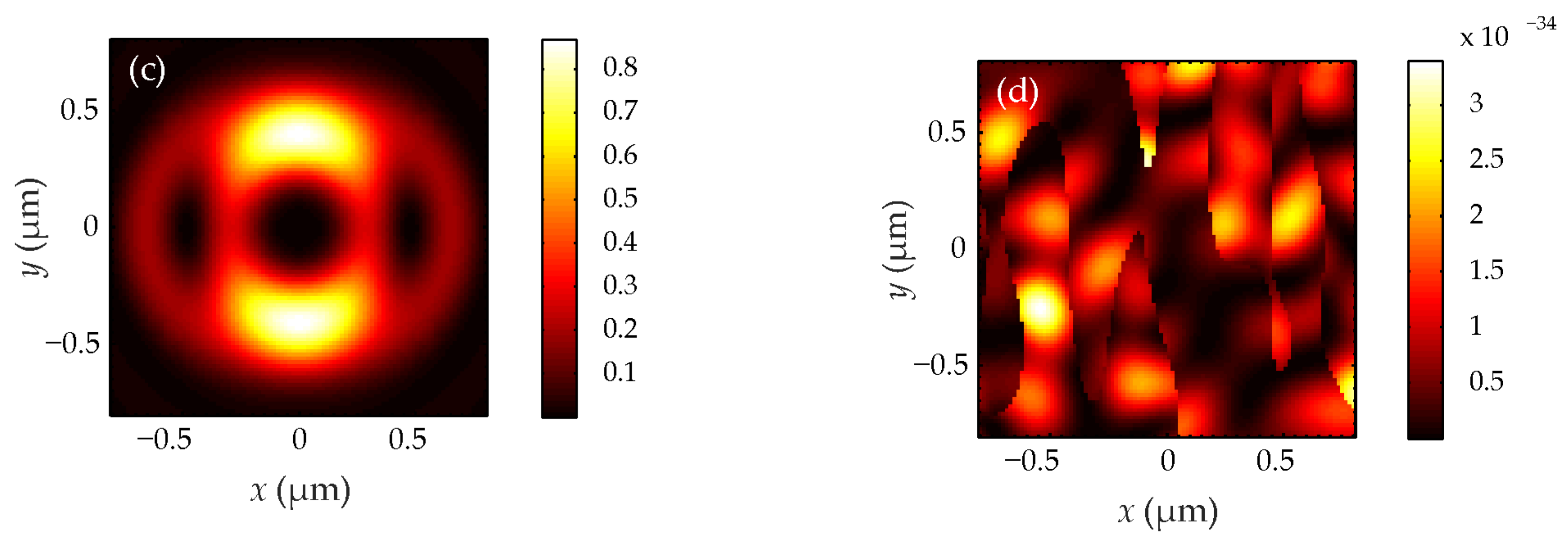
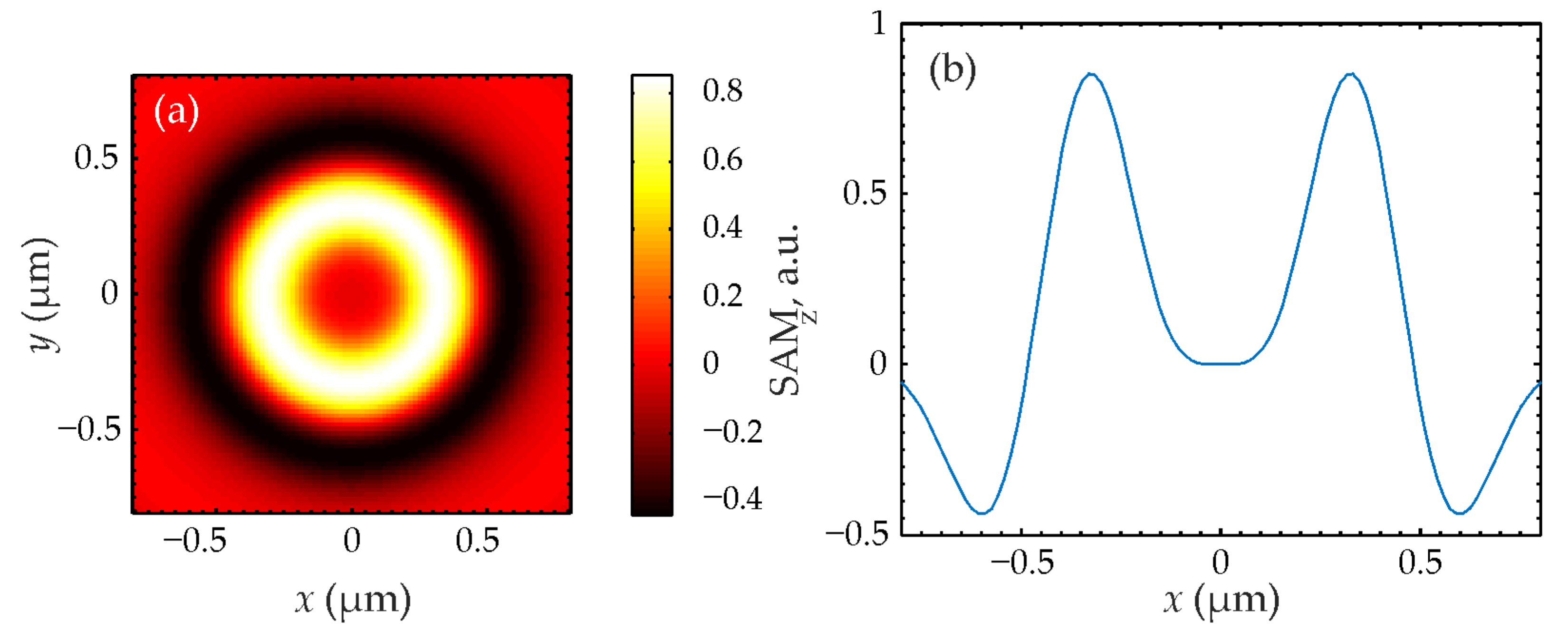
It can be seen from (35) that the SAM distribution at the focus has radial symmetry and will have different signs at different radii. For example, the SAM on the optical axis at r = 0 will be positive (right circular polarization) at n = 1 and will be negative (left circular polarization) at n = −1. When n = 0, the SAM in the entire focal plane is equal to zero. And when n is different from zero and one, the SAM on the optical axis is equal to zero and will alternate plus and minus signs with increasing of the distance from the optical axis. That is, the radial spin Hall effect will take place at the focus and the magnetization vector (30) will have only a longitudinal component (31).
For the sake of completeness, we present the expression for the total intensity at the focus and for the intensity of transverse projections of the initial field (32):
It can be seen from (36) that the total intensity at the focus for the initial field (32) has circular symmetry, since it depends only on the radial variable,
I =
A(
r). And transverse intensities have axial symmetry, since when the angle ϕ is replaced by ϕ + π, the intensity pattern does not change. Also, a feature of the transverse intensity (36) is that the intensity
Ix transforms into the intensity
Iy when the angle φ is rotated by π/2. It is also clear from (36) that for a TC
n = 1 or
n = −1 a round light spot is formed at the focus of the field (36), since the intensity on the optical axis is equal to the expression:
The expression (37) is greater than zero because integrals (18) with the second index equal to zero have a zero-order Bessel function J0(ξ) under the integral, which at zero is equal to one: J0(0) = 1. A light ring will form at the focus for other values of the TC. These findings will be confirmed using simulations in the next section.
6. Numerical Simulation Results
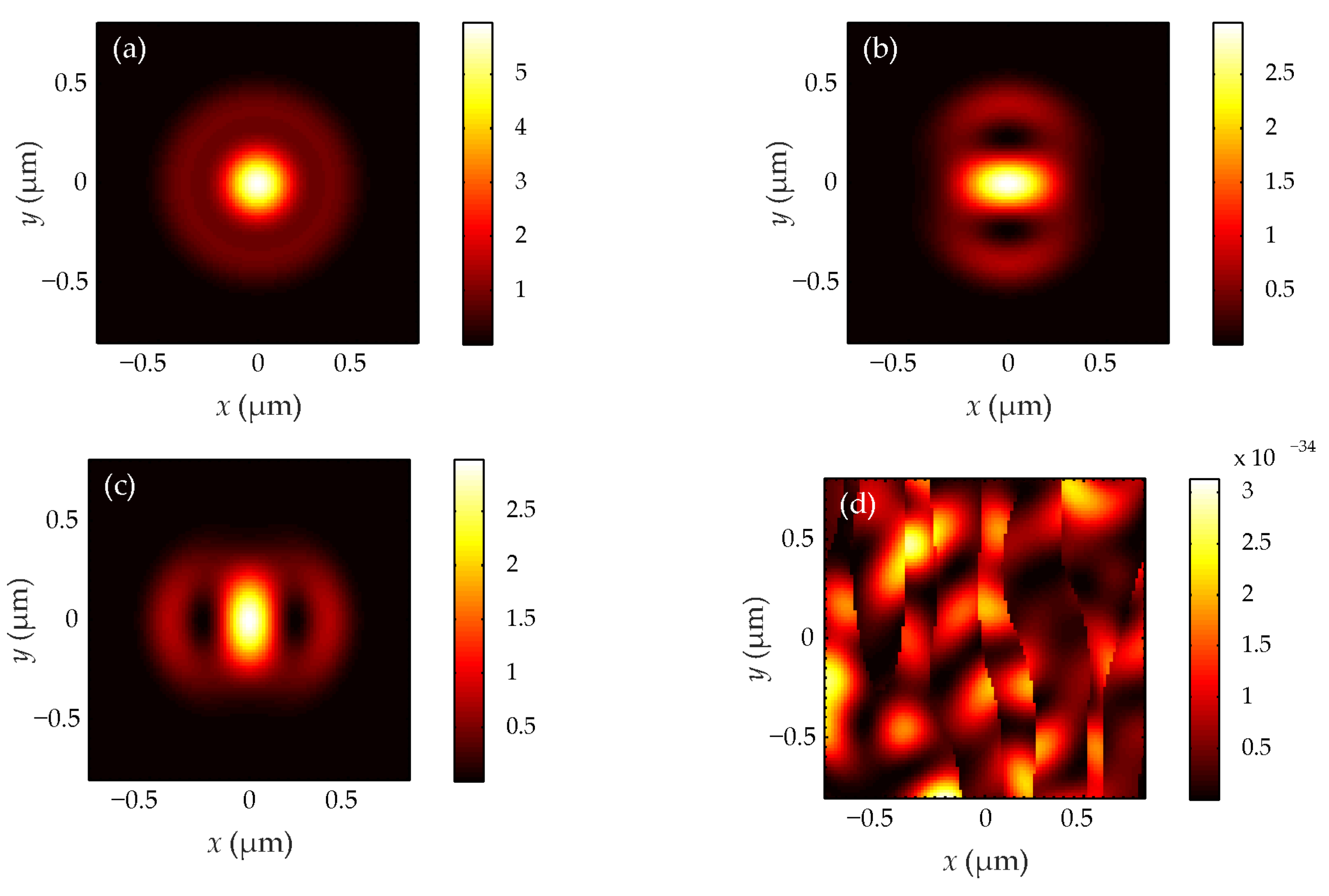
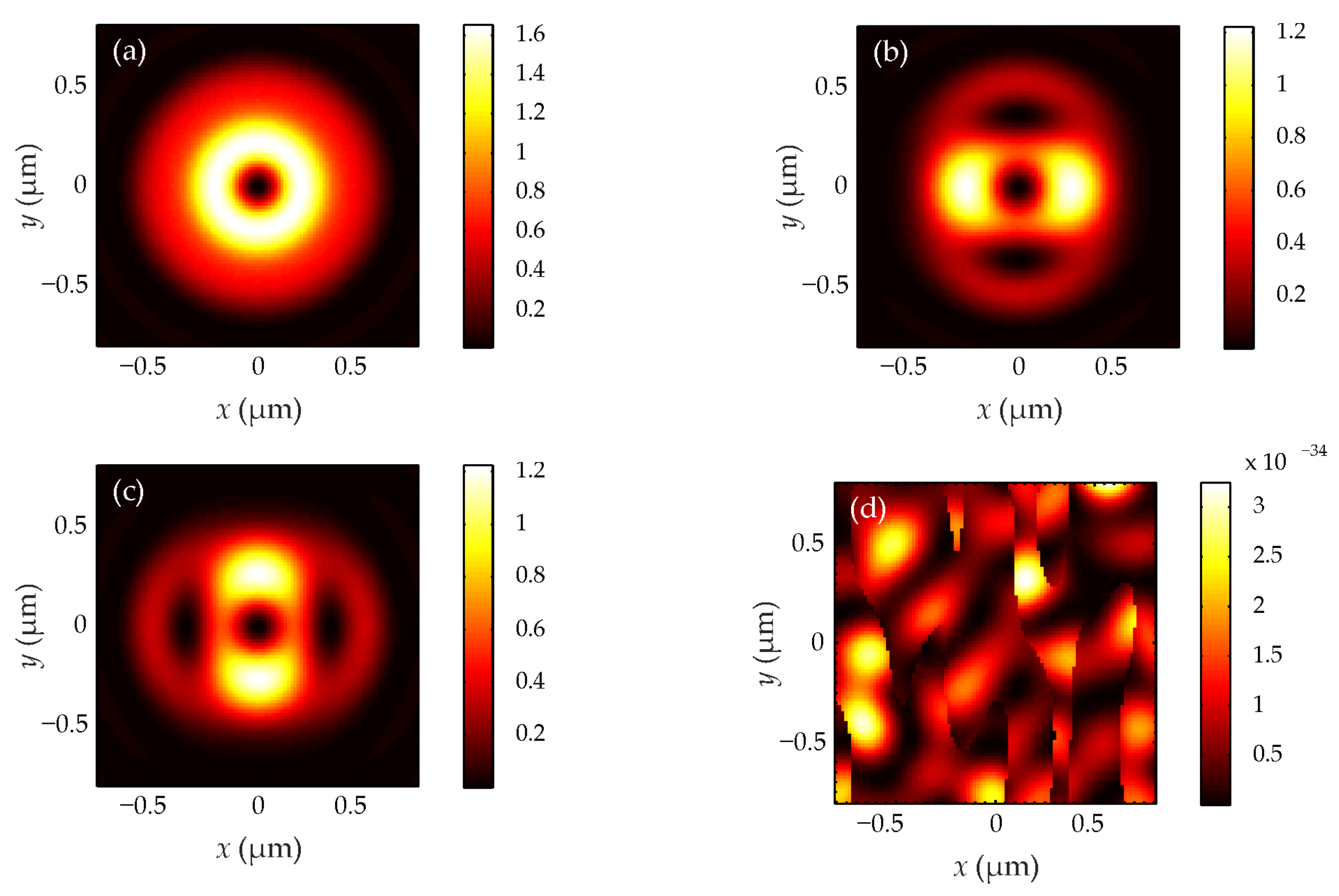
Using the Richards–Wolf integral (1), the focusing of a beam (32) with a wavelength of 532 nm and TCs of 1 (
Figure 1 and
Figure 2), 2 (
Figure 3 and
Figure 4) and 3 (
Figure 5 and
Figure 6) by an aplanatic lens (
T = cos
1/2θ) with numerical aperture NA = 0.95 was modeled. Intensity distributions are shown in
Figure 1,
Figure 3 and
Figure 5, and longitudinal components of the SAM are shown in
Figure 2,
Figure 4 and
Figure 6.
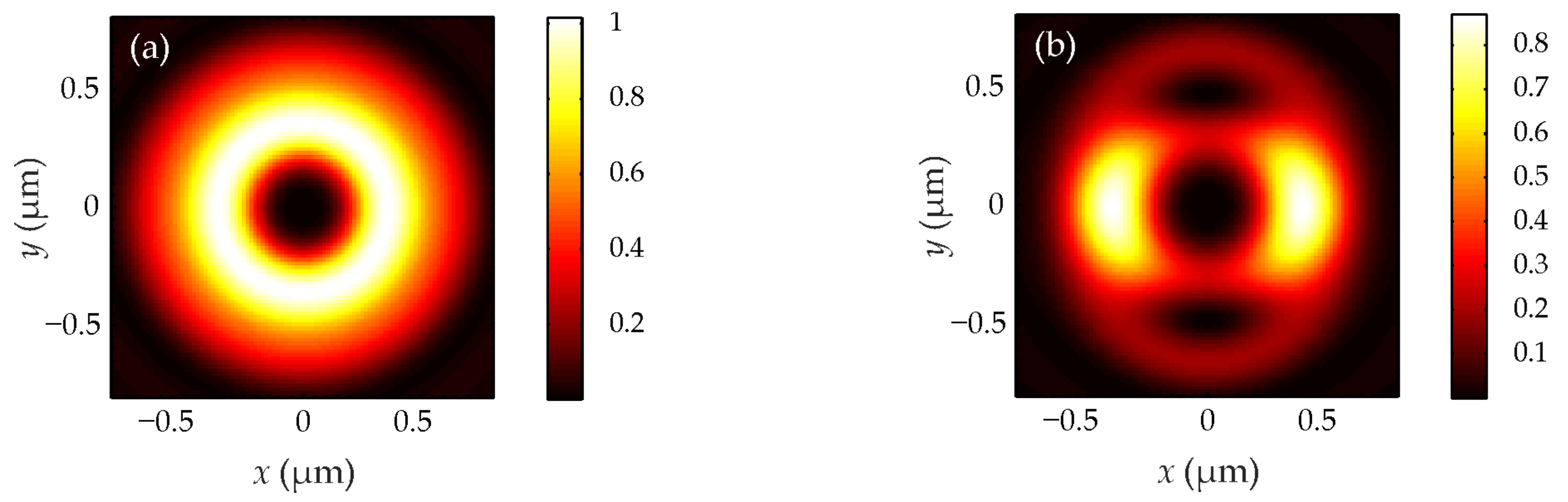
Figure 1,
Figure 3 and
Figure 5 demonstrate that when
n = 1, the light field has the form of a round light spot at the focus, and when
n = 2, 3, the focus has the form of a ring. Transverse intensity projections in
Figure 1,
Figure 3 and
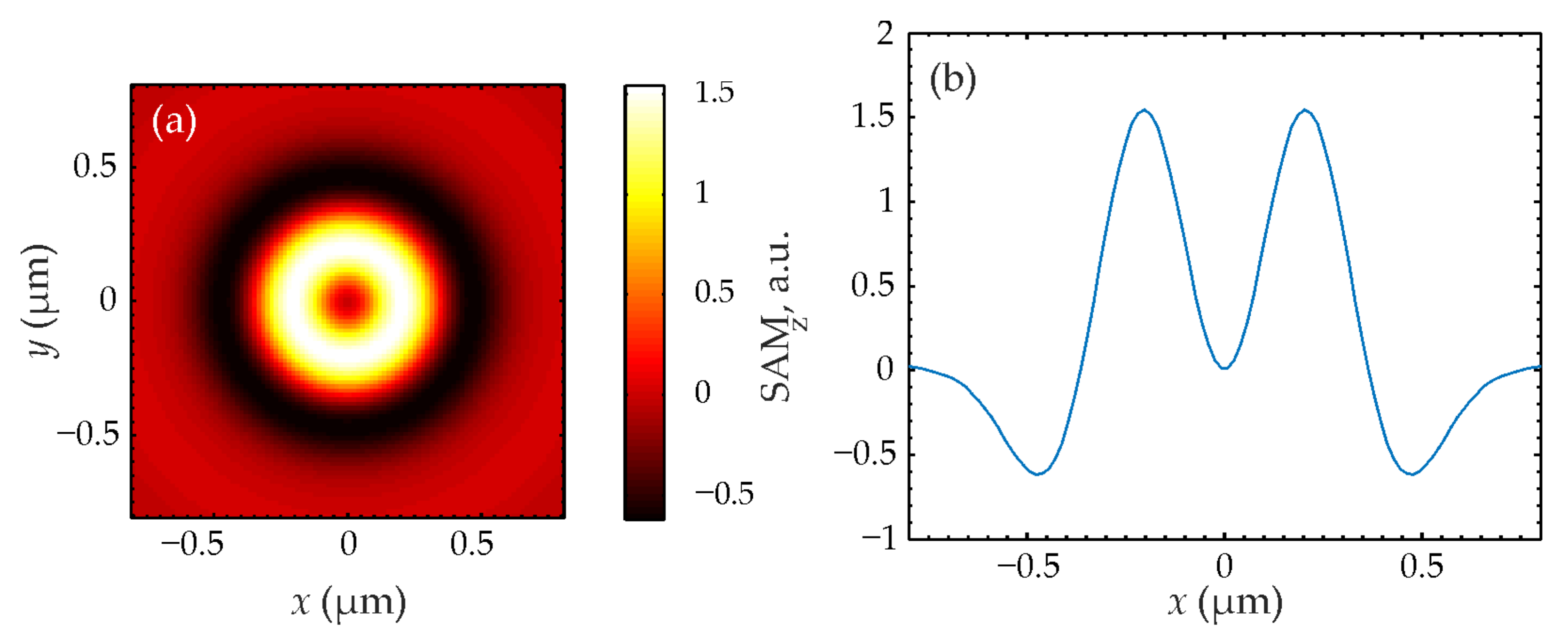
Figure 5 transform into each other when rotated by π/2. The field (32) has no longitudinal intensity component. The longitudinal projection of the SAM in
Figure 2,
Figure 4 and
Figure 6 has circular symmetry according to (35). At
n = 1,
Figure 4 shows that the SAM is maximum on the optical axis and positive, that is, the right-handed circular polarization takes place near the optical axis at the focus of the field (32) and the polarization vector rotates counterclockwise. Therefore, such a light field is used to magnetize materials using the inverse Faraday effect [
29]. Also, it can be seen from
Figure 4 that the SAM changes sign and the central region with positive spin is surrounded by a ring region with the negative spin so that the total spin is equal to zero, as in the initial plane of the field (32). The separation of regions with spins of different signs at the focus is a manifestation of the radial spin Hall effect. It is clear from
Figure 4 and
Figure 6 that the right-handed elliptical polarization is formed on a light ring centered on the optical axis at a TC
n > 1 at the focus. And it is surrounded by a ring with the left-handed circular polarization. The larger the value of
n > 1, the larger the radii of these rings, and the more the polarization ellipses are extended.
7. Conclusions
In this study, using the well-known Equations (1)–(4), it is shown that the longitudinal projection of the SAM immediately behind the spherical lens decreases (6), and if there was no OAM before the lens, then the OAM appears immediately after the lens (15). In this case, the sum of the longitudinal SAM and OAM is preserved (16). That is, the SOC occurs immediately behind the spherical lens. However, the azimuthal energy flux, which is usually present in the light fields with OAM is zero, immediately behind the lens (12). The azimuthal energy flow appears at the focus (13). Also, the spin Hall effect immediately behind the lens is zero (22), and it reaches a maximum (23) at the focus. This phenomenon can be described as follows: Optical vortices of varying topological charges and disparate circular polarizations manifest within the converging field (22) located immediately behind the lens. But since their amplitudes are equal, the total spin remains equal to zero. As focusing occurs, optical vortices with different TCs diverge differently due to diffraction in free space. Therefore, different vortices will have different amplitudes at the focus and their sum will have spins of different signs in different regions of the focal plane (23).
Equation (2) allows us to find the general form of the initial vector field (29), which does not have a longitudinal projection of the electric field strength vector (33) at the focus. Such fields at the focus have only a longitudinal projection of the SAM (35), which, under certain parameters, can have a maximum on the optical axis. For such fields, the magnetization vector has only a longitudinal component (31). Such light fields are used to magnetize materials due to the inverse Faraday effect [
29,
30,
31]. Studies concerned with practical uses of high-NA spherical lenses can be found in Refs. [
32,
33,
34,
35,
36]. In [
32], the axial and transverse resolution of an immersion spherical lens with NA = 1.4 was improved via using a ring mask. In Ref. [
33], a metalens with NA ~ 0.9 for a wavelength of λ = 633 nm was synthesized in a thin-film amorphous silicon and shown to generate a smaller focal spot measuring 0.37λ on one axis. In Ref. [
34], the numerical simulation of a graded-index lens with radial refractive index profile for a millimeter wavelength range of 9–13 GHz revealed that the lens could resolve two point light sources separated by λ/3. The study in Ref. [
35] proposed an ultracompact solution to combat the longstanding requirement of on-chip beam structuring source via monolithic integration of dielectric metasurfaces with vertical cavity surface-emitting lasers. The metasurface of interest was composed of 500 nm high rods synthesized in a GaAs film, generating a 3 × 3 set of beams for a wavelength range of 970–990 nm. In Ref. [
36], a dual-band multifocal diffractive lens was designed and shown to simultaneously focus a 633 nm beam at a 80 mm distance and a 808 nm beam at a 110 mm distance. All types of lenses described above can be utilized for experimental studies of the SOC effect at the strong focus of laser light.

 ,
, 