Abstract
A microwave photonic frequency-doubling phase shifter with a broad bandwidth and large tuning range is proposed in this paper. Frequency doubling and phase shifting are realized by processing the input microwave signal in the optical domain at a dual-drive dual-parallel Mach–Zehnder modulator (DD-DPMZM) and a dual-parallel Mach–Zehnder modulator (DPMZM). The input signal is split into two branches through a 90-degree hybrid splitter. One signal is sent to the DD-DPMZM to achieve a phase-shifted carrier-suppressed up-sideband by tuning the bias voltage, and the other is sent to the DPMZM to realize a carrier-suppressed down-sideband. By beating the phase-shifted up-sideband and the down-sideband at a photodetector (PD), the input signal is frequency doubled and phase shifted. The proposed frequency-doubling phase shifter is simulated. The results show that the frequency-doubled signal has a phase-tuning range from 0 to 360 degrees. In addition, the influence of the amplitude and phase unbalance of the 90-degree hybrid splitter on the magnitude variation and phase deviation of the frequency-doubling phase shifter is studied.
1. Introduction
Traditional phased array radars, broadband wireless communications, and remote sensing use electrical phase shifters used to realize the phase control of RF signals [1,2,3]. However, their performance is not satisfactory due to the limited bandwidth and phase-shift range of the electrical phase shifters. The emergence of microwave photonics solves these problems well [2,3]. The RF signals are modulated onto an optical carrier and processed in the optical domain [4]. Thanks to the advantages of the small volume, lightweight, low loss, large bandwidth, and anti-electromagnetic interference, photonic techniques are widely used to create broadband phase shifters with a 360-degree shifting range [5,6,7,8,9,10,11,12].
For example, phase shifting can be realized by tuning the optical wavelength incorporating stimulated Brillouin scattering (SBS) [5]. A long fiber and a high-power optical pump are usually used for the SBS operation. To reduce the size, photonic-integrated micro-ring resonators (MRRs) are used to tune the phase [6,7,8]. However, the bandwidth is limited when using a single MRR [6,7]. To solve this problem, two MRRs are used [8] in the phase shifter. Furthermore, magnitude deviations resulting from the notch-magnitude response of the MRR should be noted in the design of MRR-based phase shifters. Another approach to implementing phase shifting is using electro-optic modulators (OEMs), such as dual-polarization dual-parallel Mach–Zehnder modulators (MZMs) [9], dual-polarization MZMs [10], bidirectional phase modulators [11], or dual-drive dual-parallel MZMs [12]. In OEM-based phase shifters, the phase shifts are usually implemented by adjusting the bias voltage. In addition, the system generally contains an optical filter, which can limit the system’s frequency response, especially at a low frequency, due to the limited edge steepness of the optical filter.
With the development of modern radar systems, multi-function operations within one system are becoming more critical [13,14]. In particular, microwave phase shifters with the capacity of frequency multiplying are emerging in the study of microwave photonics [15,16,17,18,19,20]. For example, a microwave phase shifter with the capacity of frequency doubling can be achieved by using a phase modulator and a programmable optical filter. The ±1st order sidebands of the modulated optical signal are chosen, and one of the selected sidebands has a tunable phase shift applied by the filter [15]. A frequency-quadrupling phase shifter can be realized using OEMs and optical filters. The optical filters choose the ±2nd order sidebands of the modulated signal generated from the OEMs, and one of the selected sidebands is phase shifted by tuning the bias voltages of the OEMs [16,17]. The limited steepness of the optical filter limits the frequency response of the phase shifter. To overcome this limitation, filter-less frequency-doubling phase shifters [19,20] are proposed based on OEMs, where ±1st-order sidebands from dual-parallel polarization modulators [19] or dual-polarization dual-parallel MZMs [20] are injected into the polarization modulator to achieve the phase shifting. However, polarization control is of great necessity in the filter-less frequency-doubling phase shifters mentioned above.
In this paper, we propose and demonstrate a microwave photonic frequency-doubling phase shifter without optical filtering and polarization controlling. The system consists of a laser diode (LD), a dual-drive dual-parallel Mach–Zehnder modulator (DD-DPMZM), a dual-parallel Mach–Zehnder modulator (DPMZM), and a photodetector (PD). The RF signal is divided into two branches and modulated at the DD-DPMZM and the DPMZM. By tuning the bias voltage, a phase-shifted carrier-suppressed (CS) up-sideband signal and a CS down-sideband signal are generated at the outputs of the DD-DPMZM and DPMZM, respectively. Then, beating the two CS single-sideband (CS-SSB) signals at the PD, a frequency-doubling and phase-shifting signal is generated. Thanks to the broad bandwidth of the optoelectronic devices, the phase shifter has a large 3 dB bandwidth. The phase shifting is realized by adjusting the direct-current (DC) bias voltage of the DD-DPMZM. Hence, the phase shifter has the advantages of a high phase-shifting accuracy and fast tuning speed. In addition, the proposed system has better stability due to the useless polarization controlling, which is sensitive to vibrations. It should also be noted that unavoidable precise bias voltage controlling can be implemented by relatively mature electronic technology and does not destabilize the system. A frequency-doubled signal with a phase-tuning range from 0 to 360 degrees and minor magnitude variations and phase deviations were achieved in the simulation demonstration.
2. Principle
Figure 1 shows the schematic diagram of the proposed microwave photonic frequency-doubling phase shifter. A lightwave was generated from an LD and split into two branches via an optical divider (OD). In the upper branch, the lightwave was injected into a DD-DPMZM, consisting of two sub-dual-diver MZMs (DDMZM1 and DDMZM2). In sub-DDMZM1, the lightwaves at the upper and lower arms were modulated by RF signals from 180- and 0-degree ports of a 180-degree hybrid splitter (HS1), respectively. The input signal of 180-degree HS1 came from the 90-degree port of a 90-degree HS, where the input signal was the initial RF signal. In sub-DDMZM2, the lightwaves at the upper and lower arms were modulated by RF signals from 0- and 180-degree ports of a second 180-degree HS2, respectively. The input signal of 180-degree HS2 came from the 0-degree port of the 90-degree HS. In the lower branch, the lightwave was injected into a DPMZM, consisting of two sub-MZMs (MZM1 and MZM2). In the DPMZM, the lightwaves at sub-MZM1 and sub-MZM2 were modulated by RF signals from the 0- and 90-degree ports of the 90-degree HS. Then, the modulated lightwaves from DD-DPMZM and DPMZM were combined via an optical coupler (OC) and detected by a PD. In addition, an electrical amplifier (EA) can be placed after the PD to amplify the frequency-doubled and phase-shifted signal.
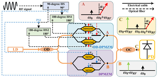
Figure 1.
The schematic diagram of the proposed microwave photonic frequency-doubling phase shifter. LD: laser diode; OD: optical divider; DDMZM: sub-dual-diver Mach–Zehnder modulator; MZM: Mach–Zehnder modulator; DPMZM: dual-parallel Mach–Zehnder modulator; DD-DPMZM: dual-drive dual-parallel Mach–Zehnder modulator; OC: optical coupler; PD: photodetector; HS: hybrid splitter; PS: power splitter; RF: radio frequency, α1: phase shifts controlled by the bias voltage, V1.
In the DD-DPMZM, both sub-DDMZM1 and sub-DDMZM2 work in a push–pull mode to eliminate the chirp effect. This is realized using two RF signals with a π phase difference to drive the sub-DDMZMs, assuming that the driven RF signals of sub-DDMZM1 are VRF1(t) and VRF2(t), given by VRF1(t) = −VRF2(t) = VRFsin(ωRFt), where VRF and ωRF are the amplitude and the angular frequency of the RF signal, respectively. The output of sub-DDMZM1 can be written as:
where Ein(t) is the lightwave from the LD, β is the modulation index, and α1 and α2 are the phase shifts controlled by the bias voltages V1 and V2, respectively. Ein(t), β, α1, and α2 are given by Ein(t) = E0exp(jω0t), β = π(VRF/Vπ), α1 = π(V1/Vπ,dc), and α2 = π(V2/Vπ,dc), respectively, where E0 and ω0 are the amplitude and angular frequency of the lightwave from the LD, respectively, and Vπ and Vπ,dc are the half-wave and switching bias voltages, respectively. The phase difference between α1 and α2 are ∆α1 = π(∆V1/Vπ,dc), where ∆V1 = V2 − V1.
By substituting the expansion of the Bessel function of the first kind, Equation (1) is rewritten as:
where Jn(β) is the Bessel function of the nth order of the first kind.
The driven RF signals of sub-DDMZM2 are V3(t) and V4(t), given by V3(t) = −V4(t) = VRFcos(ωRFt). The output of sub-DDMZM2 can be given by:
where α3 = π(V3/Vπ,dc) and α4 = π(V4/Vπ,dc) are the phase shifts controlled by the bias voltages V3 and V4, respectively. By substituting the expansion of the Bessel function of the first kind, Equation (3) is rewritten as:
where ∆α2 = π(∆V2/Vπ,dc) is the phase difference between α3 and α4, and ∆V2 = V4 − V3.
The output of the DD-DPMZM is given by:
where α5 = π(V5/Vπ,dc) is the phase shift controlled by the bias voltage, V5. By tuning V1 equals V3, corresponding to α1 = α3, and assuming a small signal modulates the DD-DPMZM, the second- and higher-order sidebands can be ignored, and the output is given by:
By tuning bias voltages V1 to V5, keeping ∆α1 = ∆α2 = π and α5 = −π/2, the output of the DD-DPMZM (Point A in Figure 1) can be rewritten as:
It can be seen that the −1st-order sideband and the carrier are eliminated, and the phase of the 1st-order sideband can be adjusted by tuning the bias voltage, V1. The relations between the bias voltages V1 to V4 are given by V2 = V1 + Vπ,dc, V3 = V1, and V4 = V2.
In the DPMZM, both the sub-MZMs (sub-MZM1 and sub-MZM2) have a built-in 180-degree phase-shifting structure and work in the push–pull mode. Assuming the half-wave and switching bias voltages of the DPMZM equal that of the DD-DPMZM, and tuning the bias voltages (V6 and V7) of the two sub-MZMs to be equal to each other, the output of the DPMZM can be given by:
where the phase shifts α6 and α8 controlled by bias voltages V6 and V8 are given by α6 = π(V6/Vπ,dc) and α8 = π(V8/Vπ,dc), respectively. By tuning bias voltages V6 and V8 to make α6 and α8 equal π and π/2, respectively, the output of the DPMZM (Point B in Figure 1) is rewritten as:
Then, the output lightwaves of the DD-DPMZM and DPMZM are combined (Point C in Figure 1) via an optical coupler and detected by a PD. According to Equations (7) and (9), the output of the PD can be given by:
It can be seen that the input RF signal is frequency doubled and phase shifted at the output of the PD. The phase-shifting coefficient is α1, which is linearly related to the bias voltage, V1.
3. Results and Discussion
The proposed frequency-doubling phase shifter was simulated using Optisystem based on the setup in Figure 1. In the simulation, the LD had a center frequency of 193.1 THz, a power of 13 dBm, and a relative intensity noise (RIN) of about −140 dBc/Hz. The 3 dB bandwidth and the insertion loss of the DD-DPMZM and DPMZM were 40 GHz and 12 dB, respectively. Both the half-wave (Vπ) and switching bias (Vπ,dc) voltages were set to 4 V. The PD had a 3 dB bandwidth of 40 GHz, a responsivity of 0.8 A/W, and a thermal and shot noise of less than −155 dBc/Hz. The output of the PD was 30 dB amplified by an electrical amplifier with a 3 dB bandwidth of 40 GHz. The 90- and 180-degree hybrid splitters had 3 dB bandwidth of 40 GHz. The spectra of the optical signals were evaluated by an optical spectrum analyzer. The spectra and the waveforms of the electrical signals were evaluated by an electrical spectrum analyzer and an oscilloscope, respectively.
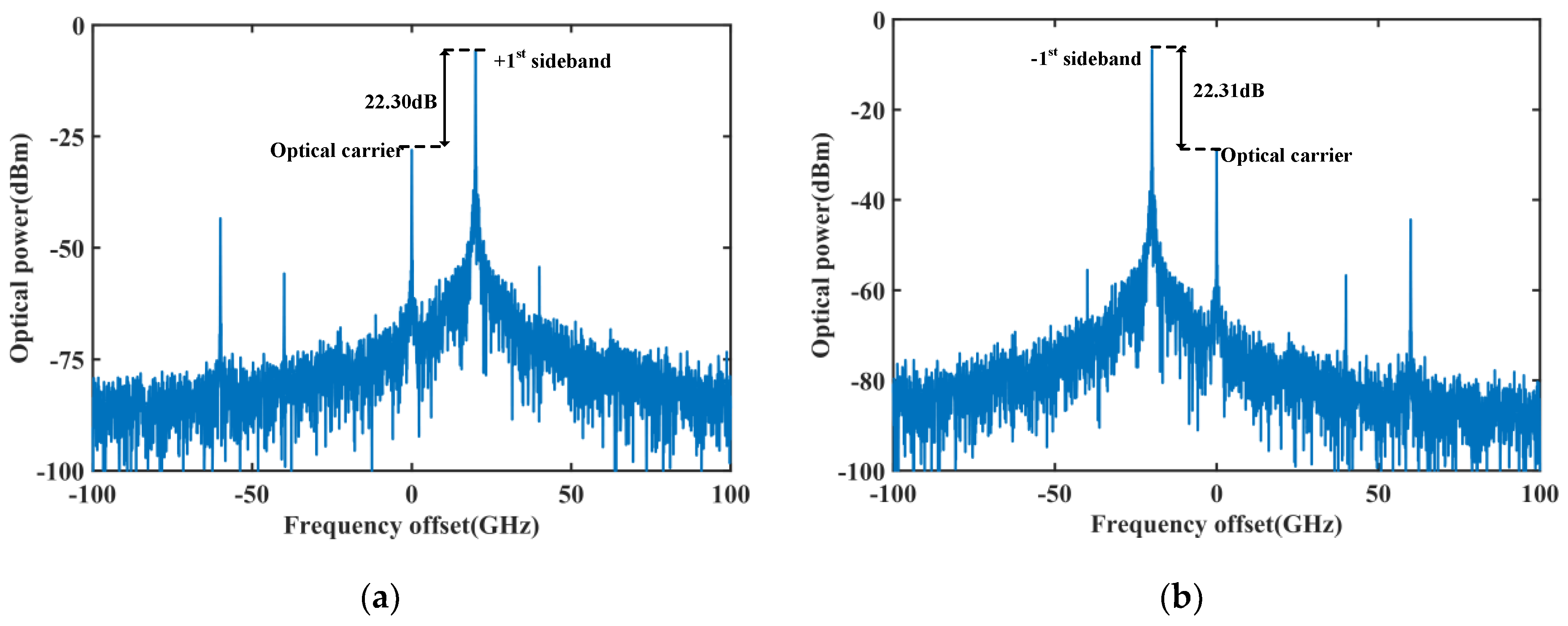
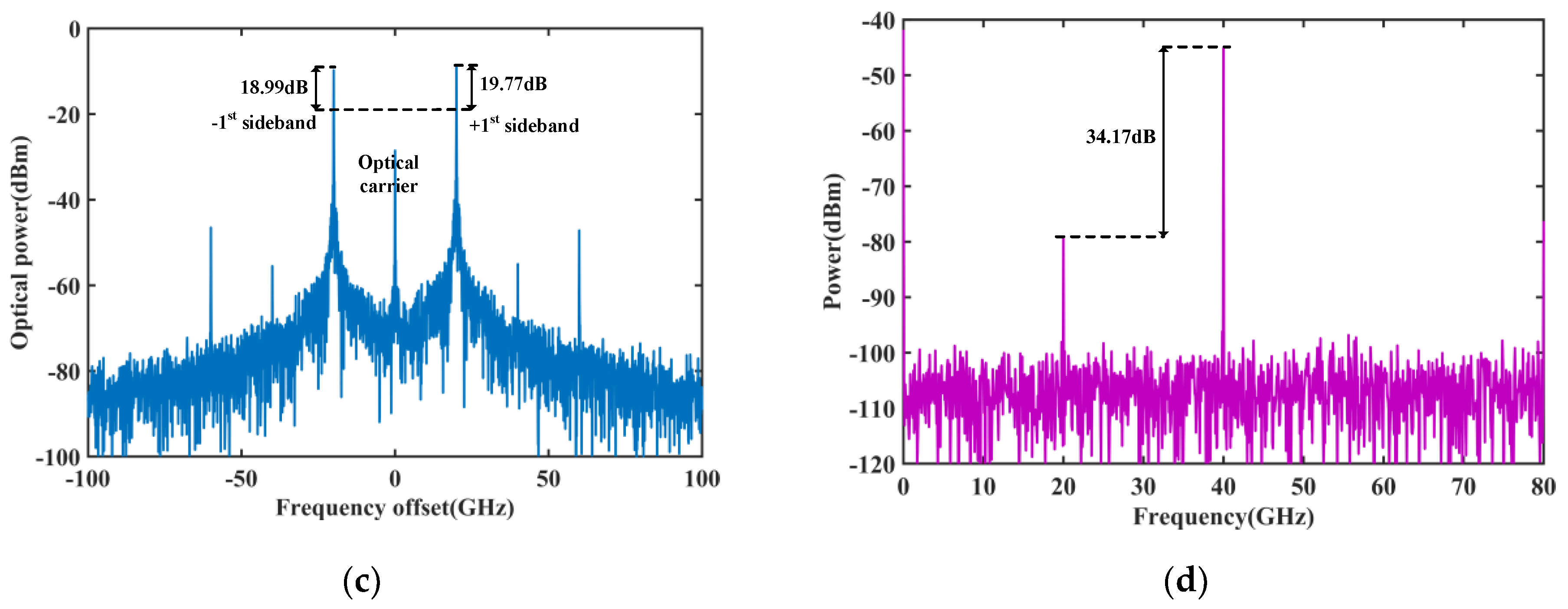
The frequency and amplitude of the input RF signal were set to 20 GHz and 1 V, respectively. By tuning bias voltages V1 to V4 to 2, 6, 2, and 6 V, respectively, the phase shifts α1 and α2 were equal to each other. In addition, both the phase differences ∆α1 and ∆α2 equaled π. Then, the DD-DPMZM worked in the condition of a carrier-suppressed single sideband (CS-SSB) modulation. Figure 2a shows the optical spectrum at the output of the DD-DPMZM. As can be seen, a CS-SSB signal is achieved, where the +1st sideband is about 22.30 dB higher than the optical carrier. A CS-SSB signal with the −1st sideband is measured in Figure 2b at the output of the DPMZM, where bias voltages V6 to V8 are set to 4, 4, and 2 V, corresponding to phase shifts α6 = π, α7 = π, and α8 = π/2, respectively. It can be seen that the −1st sideband is 22.31 dB higher than the optical carrier. Then, the output lightwaves from the DD-DPMZM and DPMZM were combined via an optical coupler. The combined signal is measured in Figure 2c, where the +1st and −1st sidebands are 19.77 and 18.99 dB higher than the optical carrier, respectively. A PD detects the combined signal, and the electrical spectrum is measured in Figure 2d. It shows that a frequency-doubled signal with a frequency of 40 GHz and a fundamental rejection of 34.17 dB is generated at the output.
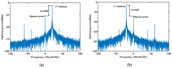

Figure 2.
The optical spectra at the outputs of the (a) DD-DPMZM and (b) DPMZM. The (c) input optical spectrum and the (d) output electrical spectrum of the PD.
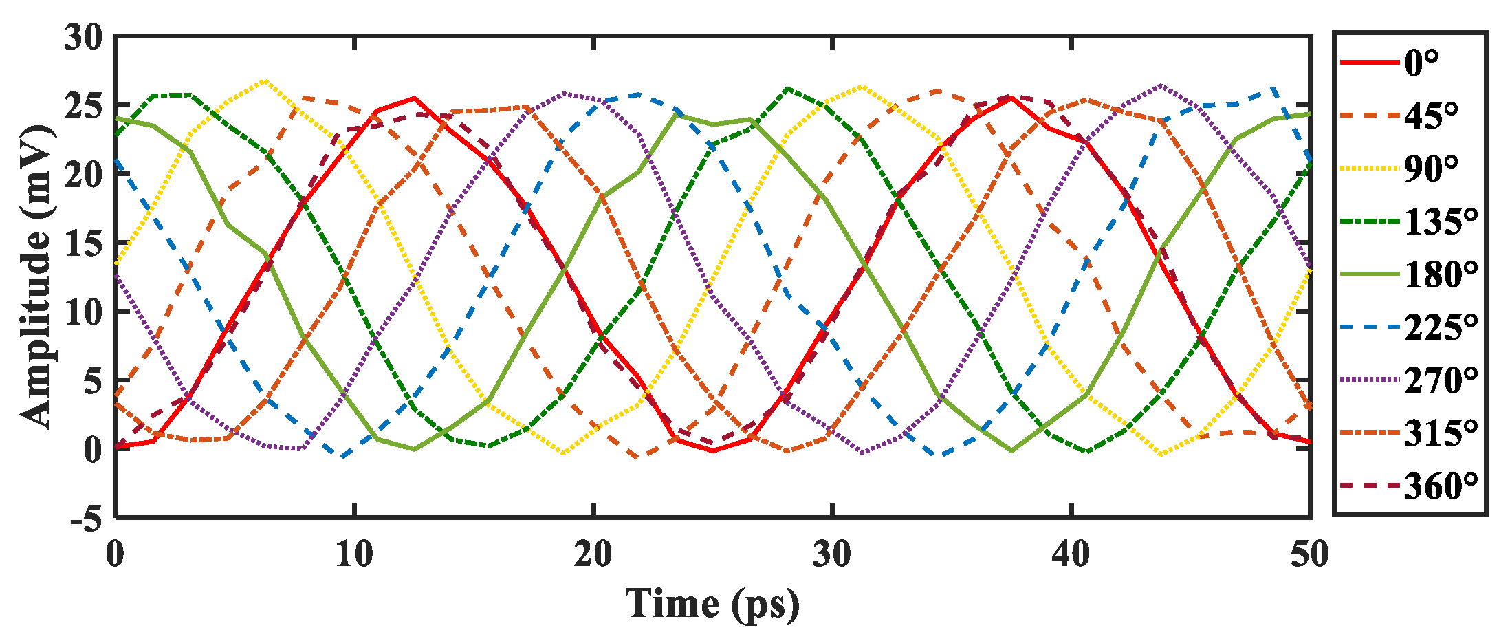
By tuning bias voltage V1 from 0 to 8 V with a step of 1 V, corresponding to a phase-shifting range from 0 to 360 degrees with a step of 45 degrees for α1, the waveforms of the generated and 30 dB amplified frequency-doubled signals are evaluated in Figure 3 via an oscilloscope with a set sampling rate of 1 Ts/s. It is shown that the generated frequency-doubled signal has a constant amplitude and a phase-shifting range of 360 degrees with a linear step of 45 degrees. The simulation results agree well with the theoretical analysis in Equation (10).
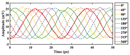
Figure 3.
The generated frequency-doubled waveforms with a 360-degree phase shifting range at the output of the PD after a 30 dB amplification.
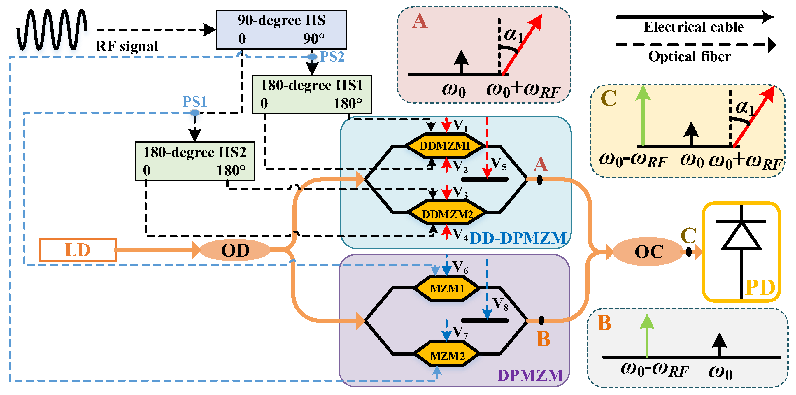
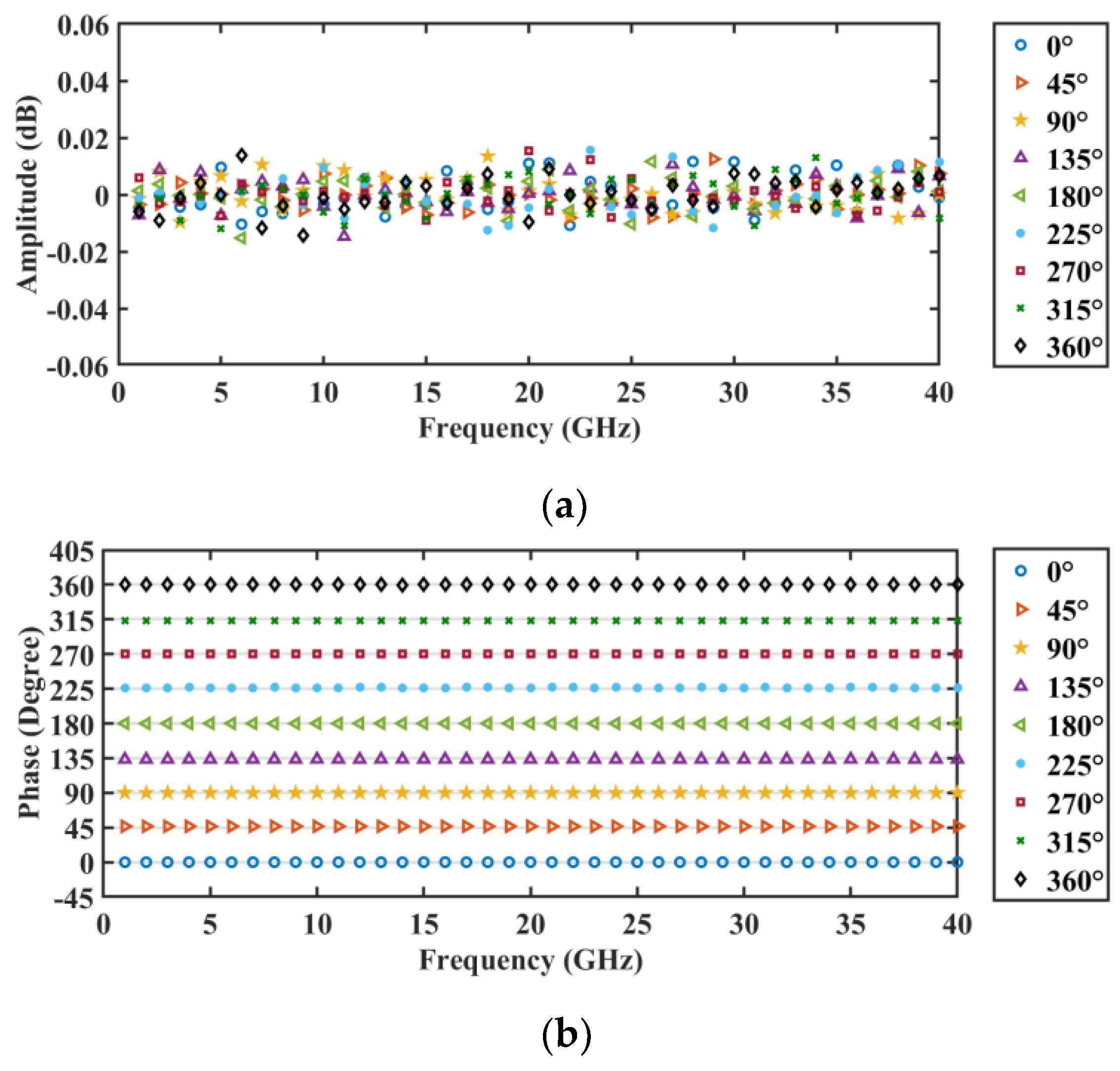
The magnitude variation and phase deviation with the frequency change were also simulated using Optisystem. The simulated results are plotted in Figure 4, where the input signals of the phase shifter have frequencies ranging from 0 to 20 GHz. As can be seen, both the amplitude and phase shifts are independent of the frequency change. This can also be explained by Equation (10), where the output amplitude and phase shift are determined by the modulation index, β, and the phase shifts, α1, respectively. In particular, both β and α1 are independent of the frequency change. Note that the ±0.02 dB magnitude variation and ±0.1 degree phase deviation resulted from the noise from the optoelectronic devices, such as the LD and PD.
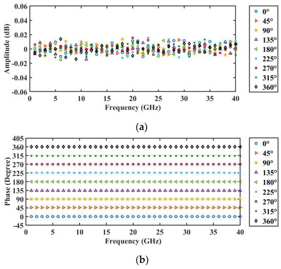
Figure 4.
The (a) magnitude and (b) phase shift responses with the frequency change of the microwave photonic frequency-doubling phase shifter.
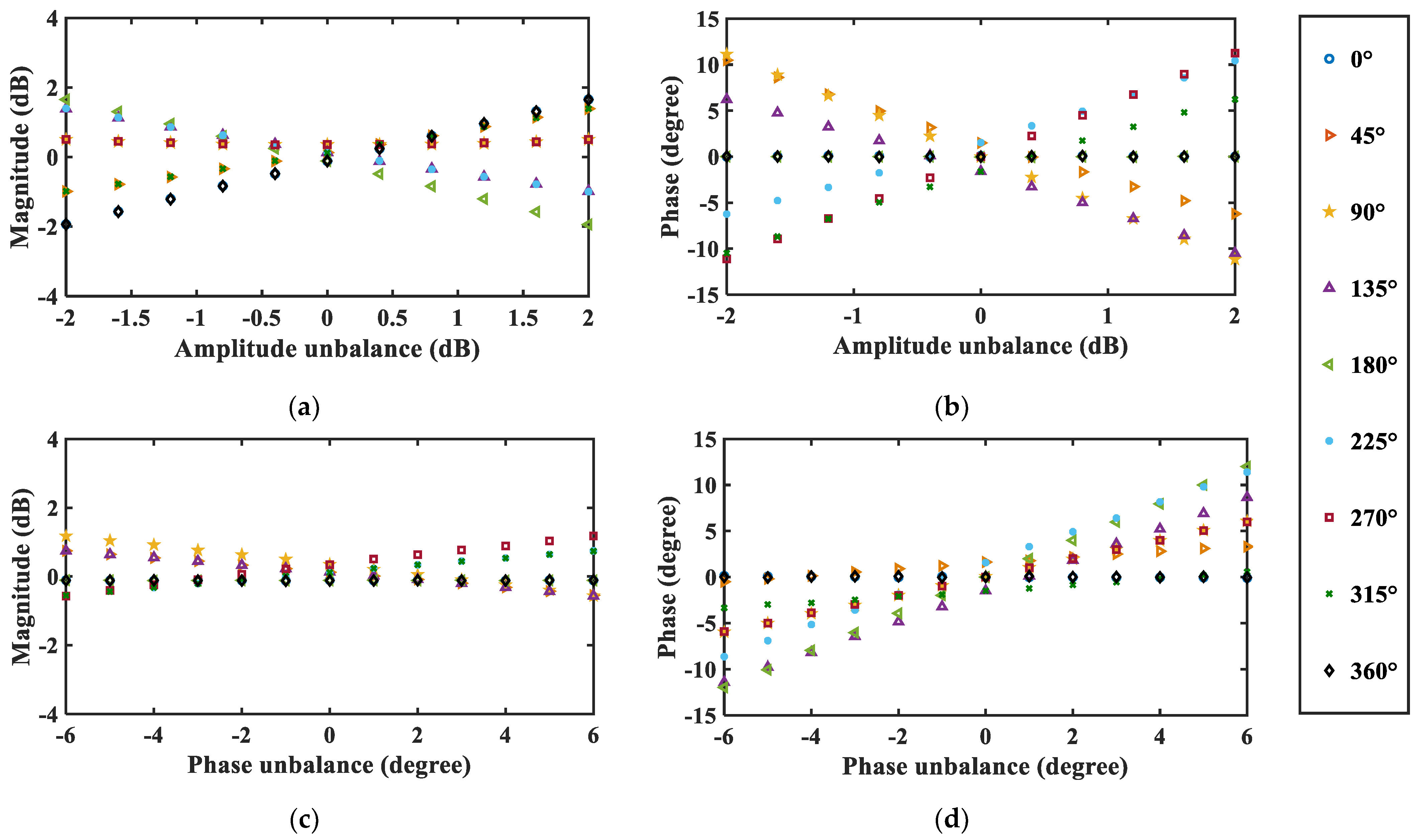
The results in Figure 4 were achieved by assuming the 90-degree HS had balanced amplitude and phase outputs. However, the amplitude and phase at the outputs of the 90-degree HS are usually unbalanced. Its effect on the output of the proposed frequency-doubling phase shifter is simulated in Figure 5. Figure 5a,b show the effect of the 90-degree HS amplitude unbalance on the output magnitude and phase shift of the proposed phase shifter, respectively. As can be seen, magnitude variations of around ±2 dB and phase deviations of about ±12 degrees for the proposed phase shifter can be observed when the 90-degree HS has amplitude unbalances ranging from −2 to 2 dB. Specifically, the maximum magnitude variation of the phase shifter is dependent on the amplitude unbalance of the 90-degree HS and can be observed when the phase shifts are 0, 180, and 360 degrees. The maximum phase deviation can be observed when the phase shifts are 90 and 270 degrees. Figure 5c,d show the effects of the 90-degree HS phase unbalance on the output magnitude and phase shift of the proposed phase shifter, respectively. When the phase unbalances of the 90-degree HS ranged from −6 to 6 degrees, the magnitude variations and phase deviations of the phase shifter were measured to be within around ±2 dB and ±12 degrees, respectively. The maximum magnitude variation was observed when the phase shifts were 90 and 270 degrees. The maximum phase deviation was observed when the phase shift was 180 degrees. It should be noted that the amplitude and phase of the 90-degree HS were set to be balanced when studying the effects of the phase and amplitude unbalances on the magnitude variation and phase deviation of the proposed phase shifter.
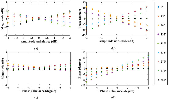
Figure 5.
The effect of the 90-degree HS amplitude unbalance on the (a) magnitude variation and (b) phase deviation of the proposed frequency-doubling phase shifter. The effect of the 90-degree HS phase unbalance on the (c) magnitude variation and (d) phase deviation of the proposed frequency-doubling phase shifter.
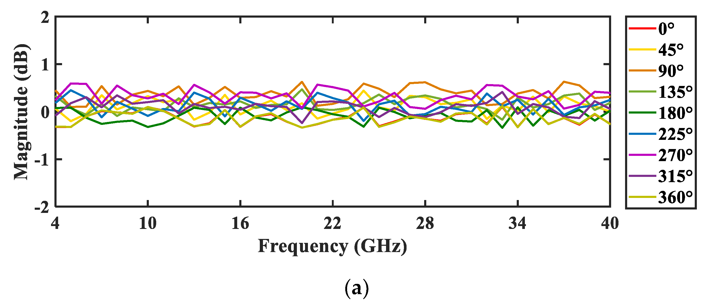
Considering the amplitude and phase unbalances of the 90-degree HS, the magnitude and phase responses of the proposed frequency-doubling phase shifter are plotted in Figure 6, where the 90-degree HS (Marki microwave, QH-0266, Morgan Hill, CA, USA) has a frequency range of 2–26.5 GHz, amplitude unbalance of ±0.25 dB, and phase unbalance of ±2 degrees. The input signals had frequencies ranging from 2 to 20 GHz; the output signals of the phase shifter had frequencies ranging from 4 to 40 GHz. Figure 6a shows the magnitude response of the phase shifter. It can be seen that the magnitude variations are within ±0.5 dB. The phase response and phase deviations of the phase shifter are plotted in Figure 6b,c. As can be seen, the frequency-doubled signals have a phase shift range from 0 to 360 degrees with an s step of 45 degrees when the tuning bias voltage, V1, shifts from 0 to 8 V with a step of 1 V. The phase deviations of the phase shifter were within ±6 degrees. According to the results in Figure 5, the magnitude variations and phase deviations of the proposed frequency-doubling phase shifter could be reduced by using a 90-degree HS with lower amplitude and phase unbalances.
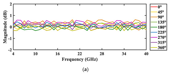
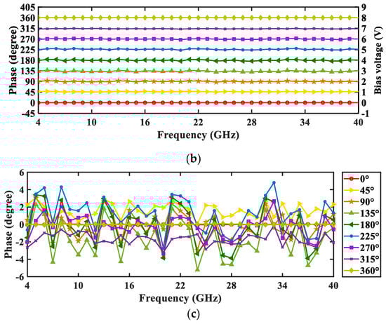
Figure 6.
The (a) magnitude and (b) phase responses of the frequency-doubling phase shifter and its (c) phase deviations.
4. Conclusions
In summary, a frequency-doubling phase shifter based on a DPMZM and a DD-DPMZM was proposed. The frequency-doubling and phase-shifting factors were realized by processing the input microwave signal in the optical domains at the DD-DPMZM and DPMZM. The optical-domain signal-processing factor was realized by adjusting the DC bias voltages of the two modulators. Hence, the proposed phase shifter could take advantage of a high phase-shifting accuracy and fast tuning speed. Thanks to the broad bandwidth of the optoelectronic devices, such as the modulator and PD, the proposed frequency-doubling phase shifter had a broad bandwidth. In addition, the effects of the amplitude and phase unbalances of the 90-degree HS on the magnitude variations and phase deviations of the phase shifter were studied. The generation of frequency-doubled signals was demonstrated over an output bandwidth of 4–40 GHz and a tunable phase shift ranging from 0 to 360 degrees.
Author Contributions
Conceptualization, J.S.; methodology, J.S.; validation, W.C. and J.S.; formal analysis, W.C. and J.S.; investigation, W.C. and J.S.; resources, J.S.; data curation, W.C. and J.S.; writing—original draft preparation, W.C. and J.S.; writing—review and editing, J.S.; supervision, J.S.; project administration, J.S. All authors have read and agreed to the published version of the manuscript.
Funding
This research was funded by the National Natural Science Foundation of China, grant number 61971110.
Institutional Review Board Statement
Not applicable.
Informed Consent Statement
Not applicable.
Data Availability Statement
The data that support the findings of this study are available from the authors upon reasonable request.
Conflicts of Interest
The authors declare no conflicts of interest.
References
- Brookner, E. Phased arrays and radars—Past, present and future. Microwave J. 2006, 49, 24. [Google Scholar]
- Capmany, J.; Novak, D. Microwave photonics combines two worlds. Nat. Photonics 2007, 1, 319–330. [Google Scholar] [CrossRef]
- Yao, J. Microwave Photonics. J. Lightwave Technol. 2009, 27, 314–335. [Google Scholar] [CrossRef]
- Minasian, R. Photonic signal processing of microwave signals. IEEE Trans. Microwave Theory Tech. 2006, 54, 832–846. [Google Scholar] [CrossRef]
- Loayssa, A.; Lahoz, F. Broad-band RF photonic phase shifter based on stimulated Brillouin scattering and single-sideband modulation. IEEE Photonics Technol. Lett. 2005, 18, 208–210. [Google Scholar] [CrossRef]
- Chang, Q.; Li, Q.; Zhang, Z.; Qiu, M.; Ye, T.; Su, Y. A tunable broadband photonic RF phase shifter based on a silicon microring resonator. IEEE Photonics Technol. Lett. 2009, 21, 60–62. [Google Scholar] [CrossRef]
- Porzi, C.; Falconi, F.; Parca, G.; Ansalone, L.; Ghelfi, P.; Bogoni, A. Fast-reconfigurable microwave photonics phase shifter using silicon microring resonators. IEEE J. Quantum Electron. 2021, 57, 1–9. [Google Scholar] [CrossRef]
- Pu, M.; Liu, L.; Xue, W.; Ding, Y.; Ou, H.; Yvind, K.; Hvam, J. Widely tunable microwave phase shifter based on silicon-on-insulator dual-microring resonator. Opt. Express 2010, 18, 6172–6182. [Google Scholar] [CrossRef] [PubMed]
- Bai, Y.; Lei, M.; Zheng, Z.; Qian, J.; Song, X.; Su, Z.; Gao, X.; Huang, S. Wideband and dispersion immune microwave photonic phase shifter with tunable optical carrier to sideband ratio. J. Lightwave Technol. 2020, 38, 5262–5269. [Google Scholar] [CrossRef]
- Peng, Z.; Wen, A.; Gao, Y.; Tu, Z. A tunable and wideband microwave photonic phase shifter based on dual-polarization modulator. Opt. Commun. 2017, 382, 377–380. [Google Scholar] [CrossRef]
- Safavi, N.; Hosseini, S. Optical SSB modulator/frequency shifter with ultralow spurious sidebands. Appl. Opt. 2020, 59, 7408–7418. [Google Scholar] [CrossRef] [PubMed]
- Huang, C.; Chan, E. Photonic-assisted microwave frequency and phase shifter for deception jamming. IEEE Photonics J. 2021, 13, 1–10. [Google Scholar] [CrossRef]
- Panda, S.; Panigrahi, T.; Parne, S.; Sabat, S.; Cenkeramaddi, L. Recent advances and future directions of microwave photonic radars: A review. IEEE Sens. J. 2021, 21, 21144–21158. [Google Scholar] [CrossRef]
- Pan, S.; Zhang, Y. Microwave photonic radars. J. Lightwave Technol. 2020, 38, 5450–5484. [Google Scholar] [CrossRef]
- Feng, Z.; Fu, S.; Tang, M.; Liu, D. Multichannel continuously tunable microwave phase shifter with capability of frequency doubling. IEEE Photonics J. 2014, 6, 1–8. [Google Scholar] [CrossRef]
- Zhang, W.; Yao, J. Photonic generation of millimeter-wave signals with tunable phase shift. IEEE Photonics J. 2012, 4, 889–894. [Google Scholar] [CrossRef]
- Wang, W.; Wen, A.; Tu, Z.; Liang, D.; Chen, M.; Li, X.; Xiao, J. Tunable 360° microwave photonic multichannel phase shifter with frequency quadrupling. Appl. Opt. 2018, 57, 4751–4755. [Google Scholar] [CrossRef] [PubMed]
- Ganjali, M.; Qashqaei, M.; Hosseini, S. Microwave photonic frequency multiplication based on Sagnac interferometer with the capability of phase shifting. Opt. Commun. 2020, 474, 126059. [Google Scholar] [CrossRef]
- Li, Y.; Pei, L.; Wang, Y.; Yuan, J. Filter-less frequency-doubling microwave signal generator with tunable phase shift. Opt. Commun. 2016, 370, 91–97. [Google Scholar] [CrossRef]
- Guo, Z.; Ma, J.; Huang, S.; Huang, S.; Gao, X. Microwave photonic phase shifter based on an integrated dual-polarization dual-parallel Mach-Zehnder modulator without optical filter. Fiber Integr. Opt. 2019, 38, 208–217. [Google Scholar] [CrossRef]
Disclaimer/Publisher’s Note: The statements, opinions and data contained in all publications are solely those of the individual author(s) and contributor(s) and not of MDPI and/or the editor(s). MDPI and/or the editor(s) disclaim responsibility for any injury to people or property resulting from any ideas, methods, instructions or products referred to in the content. |
© 2024 by the authors. Licensee MDPI, Basel, Switzerland. This article is an open access article distributed under the terms and conditions of the Creative Commons Attribution (CC BY) license (https://creativecommons.org/licenses/by/4.0/).