Article

Simple Direct Measurement of the Orbital Stokes Parameters in Structured Vortex Beams

Physics and Technology Institute, V.I. Vernadsky Crimean Federal University, Vernadsky Prospect 4, Simferopol 295007, Russia
*
Author to whom correspondence should be addressed.
Photonics 2024, 11(11), 1095; https://doi.org/10.3390/photonics11111095
Submission received: 25 October 2024 / Revised: 15 November 2024 / Accepted: 18 November 2024 / Published: 20 November 2024
(This article belongs to the Special Issue Recent Advances in Diffractive Optics)

Abstract

:
An analogy with the polarization Stokes parameters and symplectic methods of the second-order intensity moment matrix allowed us to develop a simple technique for measuring the orbital Stokes parameters followed by mapping the structured beam states onto the orbital Poincaré sphere. The measurement process involves only two shots of the beam intensity patterns in front of a cylindrical lens and in its double focus. Such a simple measurement approach is based on the reciprocity effect between the experimentally measured cross-intensity element W x y and the orbital angular momentum of the intensity moment matrix. For experiments, we chose two types of two-parameter structured beams, namely, structured Laguerre–Gaussian beams and binomial beams. We obtained a good agreement between our theoretical background and the experiments, as well as the results of other authors.

1. Introduction

Simple and reliable measurement of the orbital angular momentum (OAM) in structured vortex beams [1,2,3] with multiple degrees of freedom is one of the primary issues of modern photonics. Digital software for beam shaping and OAM mode detection, as a rule, employs spatial light modulators (SLMs) or digital micro-mirroring devices (DMDs) [4]. Typical approaches to measuring the OAM, both in a structured beam as a whole and its vortex modes, can be found in a variety of articles (see, e.g., [5,6,7,8,9,10,11,12,13], and references therein in optics and radio). Special attention is paid to the geometric representation of the OAM states of structured beams [14], in particular, their mapping onto the Poincaré sphere (see, e.g., [15,16,17,18,19,20]). The key element of the mappings is the orbital Stokes parameters. There are various approaches to calculating the Stokes parameters. Padgett and Courtial [16] were the first to carry out an elementary calculation of the orbital Stokes parameters, followed by mapping the superposition of two lower-order Laguerre–Gaussian (LG) modes onto the Poincaré sphere. Their approach was generalized by Agarwal [21] for higher-order LG modes based on SU(2) group theory and the Schwinger boson operator representation [22]. Calvo [19], considering the Berry phase manifestation during cyclic variation of the simplest one-parameter hybrid Hermite–Laguerre–Gaussian (HLG) beams [23], showed that mapping the beam states onto the orbital Poincaré sphere outlines an exceptionally flat trajectory along the main meridian. The calculation of the mapping was carried out using the Wigner representation and second-order intensity moments [24,25]. Also, Colvo showed that a controlled Berry phase can be obtained only if an additional parameter is introduced into the HLG beam state: the rotation angle due to the Dove prism (note that a justification for this assumption has only recently been obtained [26]). A rigorous theory of constructing the state of paraxial beams in terms of orbital Stones parameters, followed by mapping onto the orbital Poincaré sphere, was developed by Alieva and Bastiaans based on physically measurable second-order intensity moments [27]. Recently, we have obtained and experimentally substantiated the mapping of a spatial multi-petal pattern of a structured Laguerre–Gaussian beam (sLG) in the Poincaré sphere [28] associated with the controlled Berry phase.
Generally speaking, the technique of the second-order intensity moments is the most effective and reliable, since it allows for measurement of all ten elements of the intensity moment matrix [29,30]. This allows the properties of the paraxial light beam to be characterized in a unified way [31]. The 4D block matrix of the second-order intensity moments P consists of three independent 2D submatrices, W , M , U (see the next section), but only three elements, W x x , W y y , W x y , of the submatrix W can be directly measured experimentally for obtaining the two parameters S 1 and S 2 . The remaining S 3 parameter, associated with the OAM, is determined through them by means of additional measurements [29,32]. This is due to the fact that the OAM is stipulated by the intrinsic beam symmetry (the beam twist), and for its measurement it is required to break the initial symmetry in a certain way (see, e.g., ref. [33]). For example, in ref. [34], the authors propose performing measurements in the focal plane of the cylindrical lens, where the mixed moments M x η and M y ξ can be measured due to the W x y cross-element. However, detailed studies of this approach [35,36] have shown that this method can be applied only for paraxial beams with certain symmetry.
Thus, the goal of our article is a theoretical and experimental study of the measurement process of the orbital Stokes parameters of stable structured vortex beams based on the computer processing of two intensity pattern shots in a first-order optical system containing a cylindrical lens. The experimental results are mapped onto the orbital Poincaré sphere.

2. The Second-Order Intensity Moment Matrix

2.1. Preliminary Theoretical Background

First, let us consider the simplest properties of the sLG beam mappings. A paraxial light beam transmitting through a first-order optical system involves two stages: (a) identification of the wave features of the beam propagation in the optical system; and (b) measurement of its explicit and hidden parameters. Transmitting the light beams is conveniently treated on the basis of the symplectic 4D ABCD matrix transformations [27,37], while measuring the paraxial beams parameters falls into the domain of the symplectic 4D matrix of the second-order intensity moments [24,38]. For example, this approach makes it possible to measure the paraxial beam quality, its waist radii, the curvature radii of the wavefront, the beam twist, and its OAM, together with the vortex and astigmatic components, internal astigmatism, and many other qualities. We restrict ourselves here to treating the basic properties of the 4D intensity moment matrix, reducing it to a 2D Hermitian matrix, and determining the orbital Stokes parameters with mapping the sLG beam states onto the Poincaré sphere.
The intensity moment matrix of the Wigner distribution is written as [27]
P = W M M t U = W x x W x y M x ξ M x η W y x W y y M y ξ M y η M x ξ M y ξ U ξ ξ U ξ η M x η M y y U ξ η U η η ,
with the coordinate W and far-field U matrices
W = 1 J 00 R 2 x 2 x y x y y 2 Ψ r 2 d 2 r , U = 1 J 00 R 2 x Ψ x Ψ * x Ψ y Ψ * x Ψ y Ψ * y Ψ y Ψ * d 2 r ,
as well as the twist matrix M
M = 1 J 00 Im R 2 Ψ * r x x x y y x y y Ψ r d 2 r ,
where Ψ ( r ) stands for the beam complex amplitude, J 00 is the total beam intensity. The intrinsic geometry of the symplectic matrix P is given by the characteristic ellipses of each submatrix. For example, the characteristic ellipse of the W submatrix is
W y y x 2 + W x x y 2 2 W x y x y = det W .
As an example, consider a two-parameter sLG beam, which is defined on the basis of Hermite–Gaussian ( HG ) modes provided that each HG N k , k mode is assigned an amplitude ϵ k and a phase θ k [39]. Its complex amplitude is read as
sLG n , r | ϵ , θ = 1 n 2 2 n + n ! k = 0 N C k HG 2 N k , k r ,
where N = 2 n + , the dimensionless variables x x / w 0 , y y / w 0 , with the beam waist radius w 0 in the vector r = x , y being employed, C k = i k ϵ k ϵ , θ c k n , n + π / 4 , where ϵ k ϵ , θ = 1 + ϵ e i k θ ,
c k n , m = j = m a x 0 , k m m i n k , n 1 k j n j m k j cos n k 2 j α sin m k + 2 j α ,
Using Equations (2) and (3) with Equation (5), we obtain all the elements of the P matrix at the beam waist plane z = 0 [28]:
P s L G = K x / 2 Re M 0 2 Im M Re M K y / 2 2 Im M 0 0 2 Im M 2 K x 4 Re M 2 Im M 0 4 Re M 2 K y ,
with
K x = π 2 + 1 n ! 2 k = 0 2 n + 2 n + k + 1 2 2 n + k ! k ! ϵ k 2 c k n , n + π / 4 2 ,
K y = π 2 + 1 n ! 2 k = 0 2 n + k + 1 2 2 n + k ! k ! ϵ k 2 c k n , n + π / 4 2 ,
M = i π 2 + 2 n ! 2 k = 0 2 n + 1 2 n + k ! k + 1 ! ϵ k * ϵ k + 1 c k n , n + π / 4 c k + 1 n , n + π / 4 .

2.2. Stokes Representation

Mapping onto the Poincaré sphere involves representing the sLG beam rotation in 4D coordinate–momentum phase space. Following Alieva and M. J. Bastiaans [27], we introduce a new variable r i p / 2 and make use of the Winger transformation [28], obtaining
P = 1 J 00 R 4 r i p / 2 r i p / 2 W r , p d 2 r d 2 p ,
where
W r , p = R 2 Γ r + r / 2 , r r / 2 e i p T r d 2 r ,
where Γ r 1 , r 2 stands for a cross-spectral density function; and we obtain the Hermitian coherence matrix:
P = S 0 + S 1 S 2 + i S 3 S 2 i S 3 S 0 S 1 ,
where W r , p stands for a Wigner function.
The parameters S i , i = 1 , 2 , 3 are called the orbital Stokes parameters [40], and are set by the P matrix elements as
S 0 = 1 2 W x x + W y y + U ξ ξ + U η η ,
S 1 = 1 2 W x x W y y + U ξ ξ U η η ,
S 2 = W x y + U ξ η ,
S 3 = M x η M y ξ ,
The hidden intrinsic symmetry of the sLG beam is at once manifested in all elements of the P matrix (7). Here, the elements M x ξ = M y η = 0 turn to zero, while there are only four independent elements of the intensity moment matrix (1). The vanishing of these elements becomes clear if we remember [29] that they characterize the Gaussian curvature radii of the wave front. But the matrix elements are calculated in the plane of the beam waist, where the surface of the wavefront becomes flat. If one makes use of the general classification of laser beams in ref. [41], then the sLG beam should be classified as a beam with general astigmatism. However, note that the main feature of astigmatism is a non-vanishing invariant, equal to the difference of invariants a = i n v 2 i n v 1 , which characterizes intrinsic (or latent) astigmatism (see Equation (2.2.47) in ref. [41]). But no astigmatic transformations were used in shaping the sLG beam; only the amplitudes of the HG modes were slightly perturbed with the decomposition of the LG beam on the basis of the HG modes [39]. This is confirmed by calculations of the vortex and astigmatic component in the beam, where the OAM astigmatic component [42] becomes zero.
A typical transformation of the Stokes parameters S i i = 1 , 2 , 3 of an sLG beam n = 8 , = 1 with cyclic variations of the phase parameter is depicted in Figure 1. In Figure 1a–c, the oscillations of the orbital Stokes parameters are clearly visible, with cyclic variations of the phase parameter θ , whereas Figure 1d demonstrates the mutual synchronization of these oscillations, despite the dramatic transformations of the beam state. These drastic changes in the beam states are easy to see by comparing the curves in Figure 1a,b for the S 3 and S 2 parameters. Near θ = π , the S 2 parameter experiences a sharp burst on the background of suppressing other oscillations. Such metamorphoses of the beam states suggest new surprises when they are mapped onto the orbital Poincaré sphere and used in a direct measurement of the orbital Stokes parameters.

2.3. Mapping onto the Orbital Poincar é Sphere

First of all, we note that the Hermitian matrix (13) has an important invariant for a first-order optical system, read as S = S 1 2 + S 2 2 + S 3 2 , which describes asymmetry of the beam, and sets the radius of the sphere on the surface of which all three orbital Stokes parameters S 1 , S 2 , S 3 are set in Cartesian coordinates. The third parameter defines the OAM z = S 3 of the beam. Thus, a point on the 2D sphere is determined by the normalized parameters S ˜ 1 = S 1 / S , S ˜ 2 = S 2 / S , and S ˜ 3 = S 3 / S . But, on the other hand, the position of a point on the sphere is also given by two angles, so that S ˜ 1 = cos β cos 2 ϕ , S ˜ 2 = cos β sin 2 ϕ , and S ˜ 3 = sin 2 β , so the azimuthal position ϕ of the point (movement along the equator) is 2 ϕ = arctan S 2 / S 1 , i.e., the angular direction of the characteristic ellipse of the submatrix W , while its ellipticity angle is 2 β = arcsin S ˜ 3 , as the movement along the meridian. Unlike all previously known maps of structured beams having flat trajectories along the meridian [15,16,40], the sLG beam mapping outlines the complex spatial trajectory, the shape of which can be controlled by varying the phase parameter θ and amplitude parameter ϵ . At very high amplitude parameters ϵ , the trajectory stretches along the main meridian S 1 = 0 [28]. The petals’ maxima correspond to the OAM maxima, while their sharp minima correspond to the OAM minima in Figure 1a, with an outline something like a heart. It is easy to show [28] that a point movement on the trajectory is specified by the characteristic ellipse inclination of the intensity moments (movement along the equator) in Equation (4) and the angle of its ellipticity controlling the movement along a meridian (see also Figure 1c, Figures 4 and 5).
Thus, the closed spatial trajectory on the sphere, which arises due to the cyclic variation of the phase parameter, is associated with the geometric Berry phase [43].

3. Direct Measurement of the Orbital Stokes Parameters

The main goal of this section is to demonstrate a new technique for direct measurement of the orbital Stokes parameters based on the second-order intensity moment measurements for different types of structured vortex beams. Generally speaking, a variety of methods for measuring the main characteristics of paraxial light beams have been known since the early 2000s on the basis of symplectic intensity moment matrices [29,30,31]. However, this approach has not yet been widely used, possibly due to the strict coupling of the single shot of the intensity pattern with careful computer processing and ambiguity in the measurement of the third Stokes parameter S 3 associated with the OAM. Therefore, we focus on the details of the measurement process.

3.1. Choosing the Measurement of the Third Orbital Stokes Parameter

Our approach is based on a direct analogy between polarization and orbital Stokes parameters [15], between the measurement of the polarization Stokes parameters and the orbital parameters of Stokes. Its foundation is the formal similarity between the Hermitian coherence matrix of polarized light (see, e.g., Equations (10.8.4) and (10.8.63a) in ref. [44]) and the Hermitian matrix for orbital Stokes parameters in Equation (13). In essence, this analogy extends into the hidden geometry of intensity patterns appearing in characteristic ellipses of the intensity moments [29]. In terms of the Poincaré sphere, the position of a point on the trajectory is given by the inclination angle of the characteristic ellipse (movement along the equator) and the ellipticity angle (movement along the meridian) [28]. To measure polarization, a sequentially positioned quarter-wave plate and a polarizer are required. Six measurements of light intensity I α , γ are required at the following orientations of the axes of the polarizer and the quarter-wave plate:
S 1 pol = I 0 , 0 I 90 , 0 , S 2 pol = I 45 , 0 I 135 , 0 , S 3 pol = I 45 , π / 2 I 135 , π / 2 .
The first two measurements are carried out without a quarter-wave plate, and the third one is performed with a quarter-wave plate, the axes of which is rotated by π / 4 . It is exactly such a scheme that we follow when measuring the orbital Stokes parameters, but instead of light intensity, we measure the second-order intensity moments.
Following procedures (2) and (3), we calculated the first two orbital Stokes parameters by measuring one-shot intensity in the anterior plane of the cylindrical lens z = 0 according to ISO recommendations [32] as follows:
S 1 = W x x z = 0 W y y z = 0 ,
S 2 = 1 J 00 R 2 x + y 2 I x , y , z = 0 d x d y R 2 x y 2 I ( x , y , z = 0 ) d x d y .
The measurement of the third orbital Stokes parameter requires additional discussions. As we discussed earlier, the authors of [30,35] propose measuring through the cross-intensity moment W x y in the focal plane of the cylindrical lens. But, firstly, this will give reliable results only for a restricted group of beams with special symmetry, and secondly the beam radii w x z = f and w y z = f turn out to be different, which is unacceptable for the chosen measurement procedure. We extended this approach for measuring the third orbital Stokes parameter based on the following background [37]. In addition, simple measurements of the OAM and topological charge for single LG beams with zero radial number n = 0 [45] and arbitrary n 0 [46] in the double-focus plane z = 2 f of the cylindrical lens, where the beam radii become equal to each other w x z = 2 f = w y z = 2 f , showed reliable experimental results. Thus, we relied on two main restrictions for our measurement process:
z = 2 f , z 0 = 2 f .
Note that the requirement (21) means that all modes in the structured beam have the same beam waist radius w 0 , and therefore the same Rayleigh length z 0 = k w 0 2 / 2 . These conditions turn out to be the most optimal for measuring the third orbital Stokes parameter in accordance with the expression
S 3 = 1 J 00 R 2 x + y 2 I x , y , z = 2 f d x d y R 2 x y 2 I x , y , z = 2 f d x d y .
To explain such a choice of the S 3 parameter measurement, let us peer into the metamorphoses of the cross-element W x y and the OAM z in the interval z = 0 , 2 f after the cylindrical lens.

3.2. The Reciprocity Effect Between the OAM and the W x y Cross-Matrix Element

Generally speaking, it is conventionally assumed [47,48] that a thin cylindrical lens can instantly transform the OAM at once beyond the lens at the z = 0 plane, excluding the contribution of the eigenmodes’ Gouy phases to the structured beam during propagation. The essence of this theoretical model lies in the matrix relationship P o u t = TP i n T 1 between the matrix P i n of the intensity moments in front of the cylindrical lens and the intensity moment matrix P o u t at a distance z after the cylindrical lens, if the symplectic ABCD matrix T of the optical system is known. As far as we know, there are still no experimental confirmations of such a theoretical premise (especially for complex unstable multi-parametric structured beams). Indeed, each HG eigenmode of the structured sLG beam (for which the matrix P i n was calculated) has the same Gouy phase, which ensures stability of the sLG beam during propagation in free space. However, a cylindrical lens separates each HG mode in the x- and y-directions, changing the wavefront curvature, so that each mode acquires two Gouy phases Γ x and Γ y , which control the wavefront when propagating the asLG beam after the lens. We consider a more detailed model that stretches the OAM transition along the z-axis, as seen partially in ref. [49,50,51], taking into account the Gouy-phase effect.
The essence of our model is to employ the ABCD matrix T to obtain the complex amplitude of the structured beam after the cylindrical lens, and then, using it, to find the intensity moment matrix P o u t at some distance z after the cylindrical lens. In this case, the mode amplitude C k in Equation (5) is obtained in the form
C k = k = 0 N i k c k n , n + π / 4 e x p i k Γ x y ,
where Γ x y = Γ x Γ y , Γ x = arg 1 + i Z / 2 , Γ y = arg 1 κ x i Z / 2 , κ x = z 0 / f . The mode amplitudes obtained enable us to write the elements of the submatrix W as
W x x = w ¯ x 2 z / 4 J 0 k = 0 N 2 N 2 k + 1 ! N k ! k ! C k 2 ,
W y y = w ¯ y 2 z / 4 J 0 k = 0 N 2 k + 1 ! N k ! k ! C k 2 ,
W x y = w ¯ x z w ¯ y z / 4 J 0 k = 0 N 1 N k ! j + 1 ! Re C k + 1 C k * ,
where w ¯ x 2 = 1 Z κ x 2 + Z 2 , w ¯ y 2 = 1 + Z 2 , which indicates a different deformation of the beam cross-section during propagation after the cylindrical lens. Note that the mode factor e x p i k Γ x y disappears in the mode amplitude C k in the above-mentioned model [47,48]. At the same time, the results of our calculations and computer simulation of the intensity moment matrix P o u t in the observation plane z = 2 f completely coincide with those in ref. [47,48]. In addition, we observe mutual transformations of the cross-intensity W x y and the OAM z in the observation plane.
A diagram of the forward z W x y and inverse transitions W x y z in the sLG n = 4 , = 1 beam is depicted in Figure 2. The conversions of the intensity patterns illustrate Figure 2c. The off-mode amplitudes’ spectra C k 2 and phases β = Γ x y point at the immutability of the mode amplitude spectrum along the entire beam length Z = z / z 0 , whereas the mode phases experience dramatic changes up to the plane z = 2 f , where the neighboring k and k + 1 modes differ by π / 2 . This means that the product of the phases all amplitudes C k C k + 1 * in Equation (10) is equal to arg C k C k + 1 * = i . But this, in turn, indicates the mutual substitution of the Im and Re operations in Equation (7), and therefore points to the reciprocity of the OAM z and the cross-intensity element W x y in the z = 2 f plane relative to the z = 0 plane. Such a mutual conversion z W x y z = 2 f is depicted in Figure 2d,e. In order to impart the reciprocity effect a certain geometric representation, we mapped transitions of the sLG beam states onto the orbital Poincaré sphere when cyclically varying the phase parameter θ . As one can see from Figure 2f, successive mappings of the sLG beam states along the Z-axis are featured by rotating the pattern trajectory as a single whole around the S 2 axis (compare, e.g., with Figure 1a,b).
Thus, within the framework of our model, the sLG beam structural states after a cylindrical lens and propagating in free space until the observation plane z = 2 f is described by a simple rotating of the beam trajectory as a single whole on the orbital Poincaré sphere by 90 caused by variations of the Γ x y z Gouy phase that is the result of the reciprocity effect of the OAM and the W x y cross-intensity element of the P matrix. Such a trajectory rotation resembles a similar rotation on a standard Poincaré sphere when polarized light passes inside a quarter-wave plate or a birefringent crystal perpendicular to its optical axis [52], corresponding to the sLG beam translation through the cylindrical lens and free space right to the z = 2 f observation plane. Note that rotation around the S 2 axis can be extended to rotation around the S 1 and S 3 axes due to rotation of the cylindrical lens axis and the Dove prism. But this is beyond the scope of our article. It is worthwhile noting that in a real situation, a structured beam can distort the predicted behavior of the reciprocity effect. These distortions immediately affect the accuracy of the measurement of the third orbital Stokes parameter. A discussion of possible measurement errors is presented in the next section.

3.3. The Experiment

The multi-fold task of our research in this subsection is to experimentally verify the proposed direct technique of measuring orbital Stokes parameters and to compare them with parallel measurements based on analyzing the HG mode spectrum [28], as well as comparing them with the results of other independent studies.
A sketch of the experimental setup is illustrated in Figure 3. To ensure simultaneous measurement of the orbital Stokes parameters in different structured beams and their HG mode spectra, two optical arms are used in the experimental setup. Significantly, both measurement techniques are based only on a single shot of the intensity pattern in each optical arm, followed by digital image processing. In addition, it is important to emphasize that measurements of both the orbital Stokes parameters and the mode spectrum assume the equality of the waist radii w 0 x = w 0 y in the x-and y-directions. The technique of measuring the HG mode spectrum has been repeatedly discussed in our articles (see, e.g., refs. [46,49,53]). Therefore, we will not settle on the details, but note that the data processing of the results turns out to be very time consuming compared to measuring the orbital Stokes parameters. Therefore, we carried out measurements of the mode spectrum only in special cases of comparing different OAMs.
Measurements of the orbital Stokes parameters were performed in the direct optical arm of the experimental setup in Figure 3, so that the detector C M O S 2 was located at the plane of the double focus of the cylindrical lens. The focal length of the cylindrical lens and the radius of the mode waist w 0 for shaping the digital holographic grating in the SLM were selected so that the Rayleigh length z 0 of the Gaussian beam on the cylindrical lens was equal to double the focal length z 0 = 2 f . To measure the orbital Stokes parameters, one intensity pattern shot after the cylindrical lens was sufficient, while the orbital parameters S i were calculated on the basis of Equations (19), (20), and (22). High reproducibility of the experimental results measurements was achieved by using an SLM modulator of the type Thorlabs EXULUS-4K1/M, which enabled us to form beams containing up to 150 HG modes, while we used two complementary metal–oxide–semiconductor detectors C M O S 1 , 2 (Michrome 20). In addition, a high adjustment accuracy for choosing the detection plane after the cylindrical lens (CL) required more precise movements of the spherical lens S 4 , which were achieved using 6D optical stages with 3D displacements and 3D rotations (Thorlabs “MAX603D”).
To minimize noise and improve the accuracy of the orbital Stokes parameter measurements, we used a background subtraction method by capturing an image in the absence of the beam and subtracting it from each experimental intensity pattern shot. This approach effectively eliminated various static noise components associated with the detection system and ambient lighting. To reduce random noise spikes, temporal averaging was also applied: a series of consecutive frames were captured for each measurement, and their mean value was used for analysis. Additionally, aperture diaphragms were employed to restrict the detection zone, which minimized the impact of unwanted scattered and diffracted light components and enhanced the accuracy of the second-order intensity moment calculations. The measurement error of the HG mode spectrum C k 2 was about 8–9% and did not exceed 7% when measuring the orbital Stokes parameters.
For the measurements, we picked out two different types of stable structured beams, namely, sLG beams and their asymptotics and binomial vortex beams.

3.4. Structured sLG Beams and Their Asymptotics

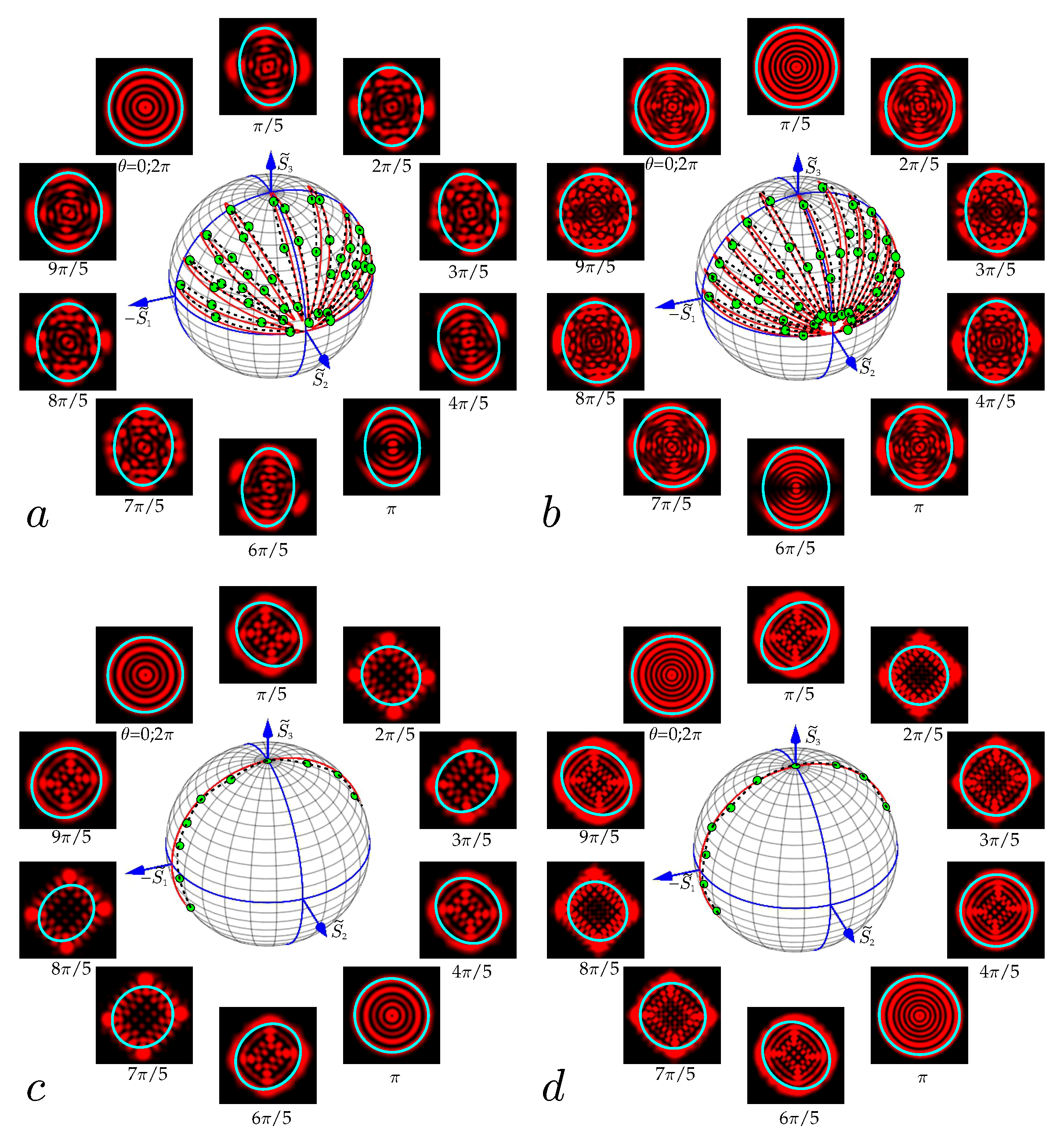
For the measurements, two sLG beams were shaped with (a,c) n = 4 , = 1 ; (b,d) n = 6 , = 1 , with amplitude parameters ϵ = 1 and ϵ = 10 4 , respectively, in accordance with Equation (5). The experimental points in Figure 4 outline the mappings of multi-petaled trajectories of these beams on the sphere according to measuring the orbital Stokes parameters in Equations (19), (20), and (22), while the solid curves are plotted using the theoretical calculations. The mean-square error of the orbital Stokes parameter measurements was calculated in accordance with the approach described in detail in ref. [34], and was no more than 5%. At this error, the theoretical curve contours are delineated inside the measurement error interval. In addition, experimental measurements were carried out in parallel by the method of the mode spectrum (amplitudes and phases) in the second arm of the experimental setup. The measurement error by this method was 7%, i.e., significantly more than the error in the orbital Stokes parameter method. The analysis indicates a good agreement between theory and experiment. In addition, as we showed in a previous study [53], the complex amplitude of the sLG beam can be represented as the sum of two types of modes: LG modes and HLG modes rotated by 135 .
sLG n , r | ϵ , θ = LG n , r + ϵ · e 3 π i / 4 2 n + n ! e i ( 2 n + ) θ / 2 HLG n , n + x + y 2 , y x 2 | θ 2 π 4 .
For small amplitude parameters ϵ 1 , the main contribution is given by the sum of both terms in (27), if ϵ 1 , then the HLG mode, which has a flat trajectory along the meridian, is responsible for the trajectory on the sphere. This is exactly the pattern in Figure 6 that is observed both in theory and experiment.

3.5. Binomial Vortex Beams

Recently, binomial one-parameter structured beams have attracted great interest due to their being able to transfer HG modes with a large OAM [54,55]. We expanded their properties by adding one more phase parameter θ , making their complex amplitude at z = 0
B i r | ϵ , θ = i N e x 2 + y 2 1 + ϵ 2 N / 2 k = 0 N ϵ k e i k θ N ! k ! N k ! H k 2 x H N k 2 y
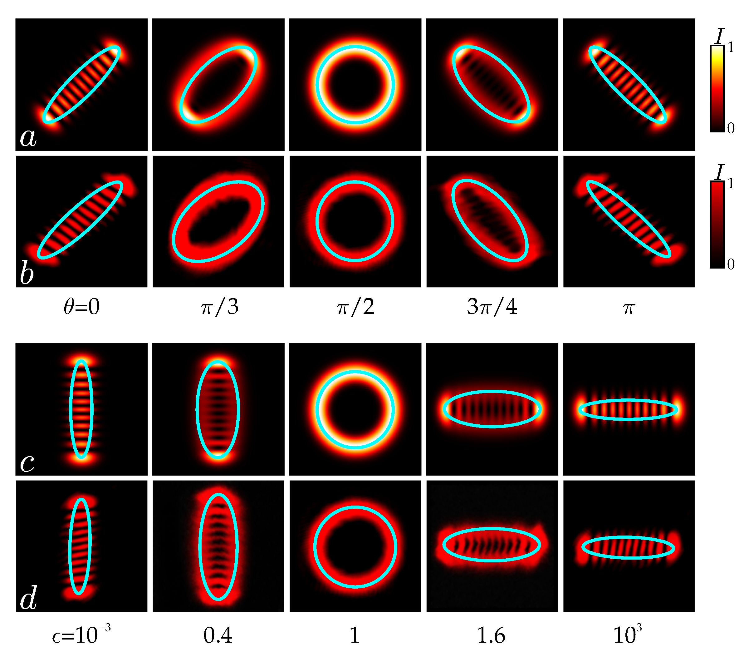
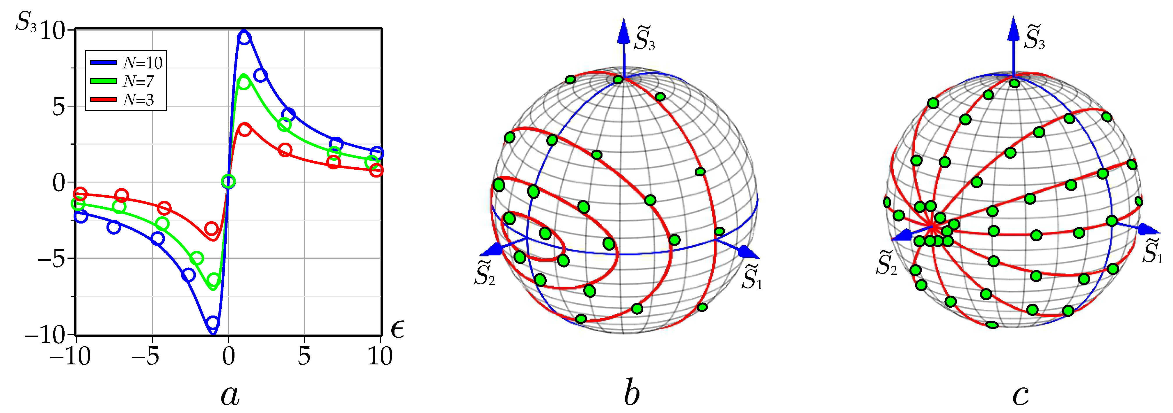
where x , y x / w 0 , y / w 0 . This expression corresponds to Equation (3) in ref. [55] for θ = π / 2 and p = q = c = d = w 0 . Variations of the ϵ and θ parameters significantly change the B i N beam states, in particular, the intensity pattern (characteristic ellipses in Equation (4)) in Figure 5a (which experience transformations when moving along a trajectory with q = p / 2 in Figure 6b). The variation in the binomial beam states is manifested in changing the intensity pattern from a purely vortex beam at θ = π / 2 to a vortex-free inclined HG beam at θ = 0 . One more intricate property of these beams is revealed when they are mapped onto the orbital Poincaré sphere, as depicted in Figure 6. Here, a family of the S 3 ϵ curves is outlined within a set of experimental points for various phase parameters θ , each of which reaches its maximum value at ϵ = 1 . If we compare the curve with θ = π / 2 with the curve of Figure 2 in ref. [55], we see a good agreement between the theory presented by the authors of this article and our experimental results, at least in the domain ϵ = 0 , 10 . For a computer simulation of mapping the evolution of the binomial beam states when cyclically varying the phase parameter, it is sufficient to make use of only the amplitudes of the HG modes in Equation (28). The family of concentric ellipse-like trajectories of the Bi-beam mappings with a cyclic change in the phase parameter θ and varying the amplitude parameter ϵ in Figure 6b embrace the S ˜ 2 axis, and collapse at the point S ˜ 2 = 1 , S ˜ 1 = S ˜ 3 = 0 at ϵ = 1 . The trajectories with ϵ > 1 are mirrored relative to a circle bounded by a trajectory with ϵ = 1 , embracing the S ˜ 2 axis. The experimental points fit tightly into the vicinity of the trajectories within the measurement error.
It is important to emphasize that the curve in Figure 6a with θ = π / 2 in the region ϵ > 0 coincides with a similar curve in Figure 2 in [55]. Such agreement with the results of a computer simulation obtained by independent authors confirms the correctness of the conclusions resulting from the reciprocity effect and also agrees well with our experimental result.
On the other hand, the amplitude parameter ϵ does not give a cyclic change in the parameters S i , but its variation from to means the parameters S 3 and S 2 tend asymptotically to zero. Variation in the amplitude parameter ϵ in the domain ϵ 50 , 50 leads to a family of circles appearing on the sphere along the meridians depicted in Figure 6c. The inclination angle of the meridians to the equatorial plane is γ = arctan S 3 / S 2 . Moreover, the function of the inclination angle γ θ depends neither on the number N nor the amplitude parameter ϵ but it experiences a discontinuity π / 2 , π / 2 at θ = π / 2 . All trajectories tighten to points S ˜ 2 = 1 and S ˜ 2 = 11 on the S ˜ 2 axis. It should be noted that the control of the spatial trajectory shape on the orbital Poincaré sphere is rigidly associated with the controlled geometric phase, as an additional degree of freedom, both in the sLG and Bi structured beams. It is also worthwhile noting that from a technical point of view this method may have limitations for real-time use, especially in conditions requiring high data processing speed. The solution to the measurement problem on real time scales may rely on improving the computer software for the processing of intensity pattern shots.

4. Discussion and Conclusions

Our experimental technique of measuring the orbital Stokes parameters is based on analogy with measuring the polarization Stokes parameters of structured beams. If the fundamental of measuring the polarization Stokes parameters is transforming the polarization light states by a quarter-wave plate and a polarizer, then the measurement of the orbital Stokes parameters involves transforming the structured beam by spherical and cylindrical lenses in a first-order optical system, followed by a computer processing of two shots of the intensity pattern before and after the cylindrical lens. Computer processing of the intensity pattern shot in front of the cylindrical lens allows one to find the elements of the matrix W . The difference between the diagonal W x x and W y y matrix elements (see Equation (19)) defines the first orbital Stokes parameter as the dominance of the squared beam waist radius along the x-direction over the squared beam waist radius in the y-direction. The difference between the non-diagonal W x y and W y x matrix elements (see Equation (20)) defines the second orbital Stokes parameter as the dominance of the squared beam waist radius along the ϕ = π / 4 -direction over the squared beam waist radius in the ϕ = π / 4 -direction. In order to measure the third orbital Stokes parameter, it is necessary to change the symmetry of the structured beam, similar to how a quarter-wave plate changes the polarization structure when measuring the third polarization Stokes parameter. But there is a significant difference. The quarter-wave plate simultaneously divides the initial polarization into two orthogonal components along the birefringence axes and brings a π / 2 phase difference between them when the light propagates. But a cylindrical lens splits the original beam into two H G ( x ) and H G ( y ) eigenmodes and only partially changes the OAM. Further structural transformations occur due to different Gouy phases when propagating after the cylindrical lens to the observation plane at a distance of the double focus of the lens, where the Gouy phases’ difference Γ x y is π / 2 . This condition is necessary and sufficient for measuring the topological charge in the vortex beams [45,46], but additional conditions are required to measure the third orbital Stokes parameter. The questions that have arisen are answered by the reciprocity effect that we have revealed. According to the reciprocity effect, there is a one-to-one correspondence between the OAM z = S 3 in front of the cylindrical lens and the cross-intensity moment W x y in its double-focus plane and vice versa. The one-to-one correspondence obtained makes it possible to measure the third orbital Stokes parameter by means of the difference of the squared waist radii in the ϕ = π / 4 and ϕ = π / 4 directions of the structured beam with modified symmetry according to Equation (22). The geometric aspect of the reciprocity effect manifests itself as rotation by π / 2 of mapping the sLG states onto the orbital Poincaré sphere when propagating the beam between the cylindrical lens and the observation plane, as depicted in Figure 2.
Although the approach for measuring the orbital Stokes parameters that we have considered does not impose any fundamental restrictions on the types of structured paraxial beams, we confined our article to stable structured beams, all modes of which have the same Gouy phases. This is due to the fact that structurally unstable beams require a detailed study of the reciprocity effect, which is beyond the scope of this article. We chose two different types of two-parameter structured beams: the structured LG and the generalized binomial Bi beams, the properties of which have been studied quite well (see, e.g., [39,54,55]).
The measurement process was carried out in two stages. In the first stage, along with direct measurements of the orbital Stokes parameters, the HG mode spectra (amplitudes and initial phases) of a structured beam was measured using the higher-order intensity moment technique that enables us to independently measure the OAM [46]. The results obtained were mapped onto the orbital Poincaré sphere in the form of spatial trajectories. The OAM measurement error in the sLG beams by the HG mode spectrum method was about 8–9%. At the same time, the average quadratic error of the OAM measured by the direct method did not exceed 4–5%, i.e., it was almost half that obtained by the spectral method. This indicates that the direct method of measuring the orbital Stokes parameters turns out to be simpler and more accurate. In addition, we compared the OAM’s dependence on the control parameter for structured binomial beams obtained by us with that obtained by computer simulation in ref. [55] and found good agreement.
The approach which we have developed for the direct measurement of orbital Stokes parameters followed by mapping onto the orbital Poincaré sphere has a number of restrictions. First of all, we are dealing with paraxial structured beams that are stable when propagating in free space. For calculations, we employed only those structured beams whose eigenmodes have the same waist radii. In addition, we required that the Rayleigh length be equal to the double focus of the cylindrical lens and the position of the observation plane. Therefore, the next step is to extend the method of direct measuring the orbital Stokes parameters to various types of unstable structured beams.
This method can be useful in imaging and sensor systems where high sensitivity to changes in objects or environments is required due to the analysis of the OAM and phase of the structured LG beam.

Author Contributions

Conceptualization, A.V. and M.B.; methodology, A.V.; software, M.B.; validation, Y.A. and S.K.; formal analysis, Y.A.; investigation, M.B. and S.K.; resources, A.V.; writing—original draft preparation, A.V.; writing—review and editing, A.V.; visualization, M.B.; supervision, A.V.; funding acquisition, M.B. All authors have read and agreed to the published version of the manuscript.

Funding

This work was supported by the Russian Science Foundation, grant no. 24-22-00278.

Institutional Review Board Statement

Not applicable.

Informed Consent Statement

Not applicable.

Data Availability Statement

The data presented in this study are available on request from the corresponding author.

Acknowledgments

We thank E. Abramochkin for a number of valuable comments when discussing the theoretical background.

Conflicts of Interest

The authors declare no conflicts of interest.

References

  1. He, C.; Shen, Y.; Forbes, A. Towards higher-dimensional structured light. Light. Sci. Appl. 2022, 11, 205. [Google Scholar] [CrossRef] [PubMed]
  2. Forbes, A.; de Oliveira, M.; Dennis, M.R. Structured light. Nat. Photonics 2021, 15, 253–262. [Google Scholar] [CrossRef]
  3. Shen, Y.; Yang, X.; Naidoo, D.; Fu, X.; Forbes, A. Structured ray-wave vector vortex beams in multiple degrees of freedom from a laser. Optica 2020, 7, 820–831. [Google Scholar] [CrossRef]
  4. Forbes, A.; Dudley, A.; McLaren, M. Creation and detection of optical modes with spatial light modulators. Adv. Opt. Photon. 2016, 8, 200–227. [Google Scholar] [CrossRef]
  5. Padgett, M.J. Orbital angular momentum 25 years on [Invited]. Opt. Express 2017, 25, 11265–11274. [Google Scholar] [CrossRef]
  6. Gbur, G.J. Singular Optics, 1st ed.; CRC Press: Boca Raton, FL, USA, 2017; p. 563. [Google Scholar]
  7. Piccirillo, B.; Slussarenko, S.; Marrucci, L.; Santamato, E. Directly measuring mean and variance of infinite-spectrum observables such as the photon orbital angular momentum. Nat. Commun. 2015, 6, 8606. [Google Scholar] [CrossRef]
  8. Suprano, A.; Zia, D.; Polino, E.; Giordani, T.; Innocenti, L.; Paternostro, M.; Ferraro, A.; Spagnolo, N.; Sciarrino, F. Enhanced detection techniques of orbital angular momentum states in the classical and quantum regimes. New J. Phys. 2021, 23, 073014. [Google Scholar] [CrossRef]
  9. Fatkhiev, D.M.; Butt, M.A.; Grakhova, E.P.; Kutluyarov, R.V.; Stepanov, I.V.; Kazanskiy, N.L.; Khonina, S.N.; Lyubopytov, V.S.; Sultanov, A.K. Recent Advances in Generation and Detection of Orbital Angular Momentum Optical Beams—A Review. Sensors 2021, 21, 4988. [Google Scholar] [CrossRef]
  10. Deng, D.; Lin, M.; Li, Y.; Zhao, H. Precision Measurement of Fractional Orbital Angular Momentum. Phys. Rev. Appl. 2019, 12, 014048. [Google Scholar] [CrossRef]
  11. Wei, H.; Xue, X.; Leach, J.; Padgett, M.J.; Barnett, S.M.; Franke-Arnold, S.; Yao, E.; Courtial, J. Simplified measurement of the orbital angular momentum of single photons. Opt. Commun. 2003, 223, 117–122. [Google Scholar] [CrossRef]
  12. Mohammadi, S.M.; Daldorff, L.K.S.; Forozesh, K.; Thide, B.; Bergman, J.E.S.; Isham, B.; Karlsson, R.; Carozzi, T.D. Orbital angular momentum in radio: Measurement methods. Radio Sci. 2010, 45, RS4007. [Google Scholar] [CrossRef]
  13. Kulkarni, G.; Sahu, R.; Magana-Loaiza, O.S.; Boyd, R.W.; Jha, A.K. Single-shot measurement of the orbital-angular-momentum spectrum of light. Nat. Commun. 2017, 8, 1054. [Google Scholar] [CrossRef] [PubMed]
  14. Shen, Y. Rays, waves, SU(2) symmetry and geometry: Toolkits for structured light. J. Opt. 2021, 23, 124004. [Google Scholar] [CrossRef]
  15. Dennis, M.R.; Alonso, M.A. Swings and roundabouts: Optical Poincaré spheres for polarization and Gaussian beams. Phil. Trans. R. Soc. A. 2017, 375, 20150441. [Google Scholar] [CrossRef]
  16. Padgett, M.J.; Courtial, J. Poincaré-sphere equivalent for light beams containing orbital angular momentum. Opt. Lett. 1999, 24, 430–432. [Google Scholar] [CrossRef]
  17. Shen, Y.; Meng, Y.; Fu, X.; Gong, M. Hybrid topological evolution of multi-singularity vortex beams: Generalized nature for helical-Ince–Gaussian and Hermite–Laguerre–Gaussian modes. J. Opt. Soc. Am. A 2019, 36, 578–587. [Google Scholar] [CrossRef]
  18. Shen, Y.; Wang, Z.; Fu, X.; Naidoo, D.; Forbes, A. SU(2) Poincaré sphere: A generalized representation for multidimensional structured light. Phys. Rev. A 2020, 102, 031501(R). [Google Scholar] [CrossRef]
  19. Calvo, G.F. Wigner representation and geometric transformations of optical orbital angular momentum spatial modes. Opt. Lett. 2005, 30, 1207–1209. [Google Scholar] [CrossRef]
  20. Tang, F.; Zhang, D.; Chen, L. Nontrivial evolution and geometric phase for an orbital angular momentum qutrit. Opt. Express 2024, 32, 21200–21215. [Google Scholar] [CrossRef]
  21. Agarwal, G.S. SU(2) structure of the Poincaré sphere for light beams with orbital angular momentum. J. Opt. Soc. Am. A 1999, 16, 2914–2916. [Google Scholar] [CrossRef]
  22. Schwinger, J.; Biedenharn, L.C.; Van Dam, H. Quantum Theory of Angular Momentum, 1st ed.; Academic Press: New York, NY, USA, 1965; p. 229. [Google Scholar]
  23. Abramochkin, E.G.; Volostnikov, V.G. Generalized Gaussian beams. J. Opt. A: Pure Appl. Opt. 2004, 6, S157–S161. [Google Scholar] [CrossRef]
  24. Bastiaans, M.J. Wigner distribution function and its application to first-order optics. J. Opt. Soc. Am. 1979, 69, 1710–1716. [Google Scholar] [CrossRef]
  25. Alieva, T.; Bastiaans, M.J. Evolution of the vortex and the asymmetrical parts of orbital angular momentum in separable first-order optical systems. Opt. Lett. 2004, 29, 1587–1589. [Google Scholar] [CrossRef] [PubMed]
  26. Yang, L.-P. Geometric phase for twisted light. Opt. Express 2023, 31, 10287–10296. [Google Scholar] [CrossRef]
  27. Alieva, T.; Bastiaans, M.J. Phase-space rotations and orbital Stokes parameters. Opt. Lett. 2009, 34, 410–412. [Google Scholar] [CrossRef]
  28. Volyar, A.; Bretsko, M. Mapping structured Laguerre–Gaussian beam states onto the orbital Poincaré sphere in the form of controllable spatial trajectories. J. Opt. Soc. Am. A 2024, 41, 1648–1655. [Google Scholar] [CrossRef]
  29. Nemes, G.; Siegman, A.E. Measurement of all ten second-order moments of an astigmatic beam by the use of rotating simple astigmatic (anamorphic) optics. J. Opt. Soc. Am. A 1994, 11, 2257–2264. [Google Scholar] [CrossRef]
  30. Eppich, A.; Gao, C.; Weber, H. Determination of the ten second order intensity moments. Opt. Laser Technol. 1998, 30, 337–340. [Google Scholar] [CrossRef]
  31. Nemes, G.; Serna, J. Laser Beam Characterization with use of Second Order Moments: An Overview. In DPSS (Diode Pumped Solid State) Lasers: Applications and Issues; 17 of OSA Trends in Optics and Photonics; Optica Publishing Group: Washington, DC, USA, 1998; p. MQ2. [Google Scholar]
  32. ISO 11146-2:2021; Lasers and Laser-Related Equipment—Test Methods for Laser Beam Widths, Divergence Angles and Beam Propagation Ratios—Part 2: General Astigmatic Beams. ISO: Geneva, Switzerland, 2021.
  33. Bekshaev, A.Y.; Soskin, M.S.; Vasnetsov, M.V. Optical vortex symmetry breakdown and decomposition of the orbital angular momentum of light beams. J. Opt. Soc. Am. A 2003, 20, 1635–1643. [Google Scholar] [CrossRef]
  34. Letsch, A.; Giesen, A. Characterization of general astigmatic laser beams. Proc. SPIE 2006, 6101, 610117. [Google Scholar]
  35. Alperin, S.N.; Niederriter, R.D.; Gopinath, J.T.; Siemens, M.E. Quantitative measurement of the orbital angular momentum of light with a single, stationary lens. Opt. Lett. 2016, 41, 5019–5022. [Google Scholar] [CrossRef] [PubMed]
  36. Bastiaans, M.J. Wigner Distribution in Optics. In Phase-Space Optics: Fundamentals and Applications; Testorf, M., Hennelly, B., Ojeda-Castaneda, J., Eds.; McGraw-Hill: New York, NY, USA, 2009; pp. 1–44. [Google Scholar]
  37. Bastiaans, M.J.; Alieva, T. First-order optical systems with unimodular eigenvalues. J. Opt. Soc. Am. A 2006, 23, 1875–1883. [Google Scholar] [CrossRef] [PubMed]
  38. Testorf, M.; Hennelly, B.; Ojeda-Castaneda, J. Phase-Space Optics: Fundamentals and Applications: Fundamentals and Applications., 1st ed.; McGraw Hill Professional: New York, NY, USA, 2009; p. 416. [Google Scholar]
  39. Volyar, A.; Abramochkin, E.; Akimova, Y.; Bretsko, M. Control of the orbital angular momentum via radial numbers of structured Laguerre–Gaussian beams. Opt. Lett. 2022, 47, 2402–2405. [Google Scholar] [CrossRef]
  40. Alieva, T.; Camara, A.; Bastiaans, M.J. Beam mapping on the orbital Poincaré sphere. Proc. SPIE 2011, 8011, 801160. [Google Scholar]
  41. Eppich, B. Laser Beam Characterization; Springer Series in Optical Sciences; Springer: Berlin/Heidelberg, Germany, 2006. [Google Scholar]
  42. Bekshaev, A.Y.; Soskin, M.S.; Vasnetsov, M.V. Transformation of higher-order optical vortices upon focusing by an astigmatic lens. Opt. Commun. 2004, 241, 237–247. [Google Scholar] [CrossRef]
  43. Berry, M.V. Quantal phase factors accompanying adiabatic changes. Proc. R. Soc. Lond. A 1984, 392, 45–57. [Google Scholar]
  44. Born, M.; Wolf, E. Principles of Optics, 7th ed.; Cambridge: Cambridge, UK, 1999; p. 952. [Google Scholar]
  45. Kotlyar, V.V.; Kovalev, A.A.; Porfirev, A.P. Astigmatic transforms of an optical vortex for measurement of its topological charge. Appl. Opt. 2017, 56, 4095–4104. [Google Scholar] [CrossRef]
  46. Volyar, A.; Abramochkin, E.; Egorov, Y.; Bretsko, M.; Akimova, Y. Fine structure of perturbed Laguerre–Gaussian beams: Hermite–Gaussian mode spectra and topological charge. Appl. Opt. 2020, 59, 7680–7687. [Google Scholar] [CrossRef]
  47. Beijersbergen, M.W.; Allen, L.; van der Veen, H.E.L.O.; Woerdman, J.P. Astigmatic laser mode converters and transfer of orbital angular momentum. Opt. Commun. 1993, 96, 123–132. [Google Scholar] [CrossRef]
  48. Van Enk, S.J. Geometric phase, transformations of gaussian light beams and angular momentum transfer. Opt. Commun. 1993, 102, 59–64. [Google Scholar] [CrossRef]
  49. Volyar, A.; Abramochkin, E.; Bretsko, M.; Akimova, Y. Engineering Orbital Angular Momentum in Structured Beams in General Astigmatic Systems via Symplectic Matrix Approach. Photonics 2024, 11, 191. [Google Scholar] [CrossRef]
  50. Volyar, A.; Bretsko, M.; Khalilov, S.; Akimova, Y. Structurally Stable Astigmatic Vortex Beams with Super-High Orbital Angular Momentum (ABCD Matrix Approach). Photonics 2023, 10, 1048. [Google Scholar] [CrossRef]
  51. Volyar, A.V.; Bretsko, M.V.; Khalilov, S.I.; Akimova, Y.E. Orbital angular momentum burst control in astigmatic structured beams in ABCD-matrix transforms. Comp. Opt. 2024, 48, 171–179. [Google Scholar] [CrossRef]
  52. Goldstein, D.H. Polarized Light, Revised and Expanded, 2nd ed.; CRC Press: Boca Raton, FL, USA, 2003; p. 680. [Google Scholar]
  53. Volyar, A.V.; Abramochkin, E.; Bretsko, M.V.; Akimova, Y.E.; Egorov, Y.A. Can the radial number of vortex modes control the orbital angular momentum? Comput. Opt. 2022, 46, 853–863. [Google Scholar] [CrossRef]
  54. Kotlyar, V.V.; Kovalev, A.A. Orbital angular momentum of paraxial propagation-invariant laser beams. J. Opt. Soc. Am. A 2022, 39, 1061–1065. [Google Scholar] [CrossRef]
  55. Kotlyar, V.V.; Kovalev, A.A.; Porfirev, A.P. Vortex Hermite–Gaussian laser beams. Opt. Lett. 2015, 40, 701–704. [Google Scholar] [CrossRef]
Figure 1. The computer simulation of the orbital Stokes parameters (a) S 3 , (b) S 2 , and (c) S 1 ; (d) the mapping onto the orbital Poincaré sphere with a cyclic variation in the phase parameter θ ; (e) the intensity patterns of sLG beams with associated ellipses of the submatrix W (cyan) and different values of the parameter θ , with n = 8 , = 1 , ϵ = 1 . The intensity patterns with θ = 0 , π / 4 , π / 3 , π / 2 correspond to the petals’ maxima in the trajectory.
Photonics 11 01095 g001
Figure 2. The computer simulation diagram of the sLG beam evolution with n = 4 , = 1 , z 0 = 1 m after a cylindrical lens with f = 0.5 m along the beam axis: (a,b) HG beam spectra of (a) the amplitudes, (b) phases with θ = 0.8 π , ϵ = 1 , corresponding to the OAM burst maximum for z = 2 f ; (c) intensity patterns along the beam axis. (d,e) Dependences of (d) the OAM z on the phase parameter θ , (e) the cross-element 4 W x y of the intensity moment matrix P on the phase parameter θ , when ϵ = 1 ; (f) transformations of mapping the sLG beam states along the beam axis Z = z / z 0 .
Photonics 11 01095 g002
Figure 3. Sketch of the experimental setup for both the direct measurement of the orbital Stokes parameters and directing the HG mode spectrum with the higher-order intensity moments. L s —He-Ne laser ( λ = 0.633 nm ) , L 1 3 —spherical lenses, D 1 , 2 —iris diaphragms, B s —beam splitter (50:50), C L —cylindrical lens, C M O S 1 , 2 —CMOS (complementary metal–oxide–semiconductor) cameras.
Photonics 11 01095 g003
Figure 4. The experimentally obtained mappings of the sLG beams (a,b) with ϵ = 1 and their asymptotics ϵ = 10 4 (c,d) onto the orbital Poincaré sphere for (a,c) n = 4 , = 1 ; (b,d) n = 6 , = 1 . The mappings are framed by the experimental intensity patterns corresponding to points on the sphere. Experimental associated ellipses of the submatrix W (cyan) on the background of the beam intensity patterns.
Photonics 11 01095 g004
Figure 5. Experimental intensity pattern transformations with associated ellipses (cyan) of B i beams with N = 10 : (a,b) ϵ = 1 and with different values of the parameter θ ; (c,d) θ = π / 2 and with different values of the parameter ϵ ; (a,c) theory; (b,d) experiment.
Photonics 11 01095 g005
Figure 6. Mapping of a binomial beam onto an orbital Poincaré sphere with variations in parameters: (a) The dependence of OAM S 3 on the amplitude parameter ϵ with different mode numbers N and θ = π / 2 ; (b) mappings with cyclic variation in the phase parameter θ , but different amplitude parameters ϵ ; (c) mappings with variation in the amplitude parameters ϵ but different phase parameters θ . Circles stand for experimental points, solids curves are theory.
Photonics 11 01095 g006
Disclaimer/Publisher’s Note: The statements, opinions and data contained in all publications are solely those of the individual author(s) and contributor(s) and not of MDPI and/or the editor(s). MDPI and/or the editor(s) disclaim responsibility for any injury to people or property resulting from any ideas, methods, instructions or products referred to in the content.