Article

Femtosecond Laser Fabrication of Gradient Index Micro-Optics in Chalcogenide Glass

by
Thien Le Phu
1,
Mariel Ledesma Molinero
2,
Catherine Boussard-Plédel
2,
David Le Coq
2 and
Pascal Masselin
1,*
1
Laboratoire de Physico-Chimie de l’Atmosphère, Université du Littoral-Côte d’Opale, 189A Av. Maurice Schumann, 59140 Dunkerque, France
2
Institut des Sciences Chimiques de Rennes, Université de Rennes, 263 Av. Général Leclerc, 35700 Rennes, France
*
Author to whom correspondence should be addressed.
Photonics 2024, 11(11), 1076; https://doi.org/10.3390/photonics11111076
Submission received: 14 October 2024 / Revised: 7 November 2024 / Accepted: 14 November 2024 / Published: 15 November 2024
(This article belongs to the Special Issue Advances in Ultrafast Laser Science and Applications)

Abstract

Gradient refractive index (GRIN) lenses have been widely used for many applications. However, the traditional manufacturing methods of GRIN lenses are very time-consuming and only suitable for macro-scale operations. In addition, those methods do not have the ability to produce other GRIN optical components with complex refractive index profiles like aspheric or freeform components. We report here an approach to produce GRIN micro-optical components in chalcogenide glass based on a direct laser writing technique. Using this approach, we are able to locally modulate the refractive index of the glass subtrates and create an arbitrary refractive index profile. To prove the flexibility of the method for the production of GRIN micro-optics, we fabricated GRIN micro-lenses and a micro-Fresnel axicon (Fraxicon). The optical properties of micro-lenses can be controlled by varying the writing parameters or the substrate thickness. As a result, the working distance of the micro-lenses can extend from 0 to more than 1000 μ m. Also, the micro-Fraxicon exhibits the ability to convert a Gaussian beam to a Bessel-like beam which concentrates the mid-infrared light into an approximately 1200 μ m long confinement zone.

1. Introduction

With the demand to reduce the size and weight of infrared devices while maintaining their performance, the traditional non-planar lenses show difficulties in reaching a compact and lightweight design [1,2]. To overcome these limitations, gradient refractive index (GRIN) lenses have been used as an alternative due to their advantages: flat surface, light weight, and less optical aberrations [3,4,5]. GRIN lenses are optical components that have spatial variation of their local refractive index [3,6,7]. They are fabricated by using many techniques like chemical vapor deposition [8], ion exchange [9], or heat treatment [10]. However, these techniques require complicated, time-consuming processes and are not able to produce complex index profiles. In addition, the techniques are only suitable for fabricating GRIN lenses at the macro-scale. The GRIN micro-lens was fabricated by Hudelist et al. in 2009 by using the stack-and-draw method [11], and the same technique was used to produce GRIN micro-axicon [12] and vortex phase masks [13,14]. The stack-and-draw method is able to produce arbitrary refractive index profiles but it still suffers from multi-step processing and can only be applied to a limited number of materials [13]. In contrast, the femtosecond laser direct writing (FLDW) method is very flexible in its local control of the refractive index, especially at the micro-scale [15]. This method can directly modify the refractive index inside transparent materials; so, it does not require complicated processes and is able to be used on a wide range of transparent materials, such as fused silica [16], fluoride [17], or chalcogenide [15] glasses.
FLDW was first reported in 1996 by Hirao’s reseach group [18]; the main idea involves irradiating a transparent substrate with a focused femtosecond laser beam. Due to the extremely high intensity within the focal volume of the focused beam, it is possible to induce localized changes in the material’s refractive index. The refractive index change ( Δ n n) could be either positive ( Δ n > 0 , type I index change) or negative ( Δ n < 0 , type II index change) [19]. Type I index change is due to local densification, structural changes, or the reorganization of chemical bonds [19,20], whereas type II index change is related to the rarefaction of material inside the focal volume [19]. The highest Δ n values have reached in the order of 10−2 in cases of fused silica [21], borate glass [22], phosphate glasses [23,24], and chalcogenide glass [25].
FLDW has been widely used for fabricating optical waveguides [26] and 3D photonic circuits [27,28] in one single-step process. Utilizing FLDW to fabricate GRIN Fresnel lens in chalcogenide glass has been recently reported by Delullier et al. [29]. The authors wrote in chalcogenide glass several concentric rings with different writing speeds to control the refractive index so that the optical path through the lens is equivalent to the one of a classical Fresnel lens, and a clear focusing behavior was demonstrated at a 550 nm wavelength. After that, a Fresnel axicon (Fraxicon) was also fabricated using FLDW in 2023 by Stankevič’s research group [30]. The Fraxicon was made by writing multilayer concentric rings with a constant period in a volume of a fused silica substrate. The number of layers and the vertical overlap between layers were optimized to obtain a phase delay of 2 π between the bottom and the top layers. The structure was written to have a diameter larger than 1 mm to enable the generation of a Bessel-like beam at a 515 nm wavelength.
We would like to introduce here the laser writing technique that creates a region consisting of parallel Δ n cylindrical channels inside chalcogenide glass substrates. The magnitudes of Δ n are modulated by changing the irradiation time. The technique has very high spatial resolution, approximately 1 μ m, so that by organizing the cylindical channels and their Δ n , we can easily fabricate complicated Δ n profiles.
The objective of this paper is the fabrication of GRIN micro-optics with different refractive index profiles in chalcogenide glass by using FLDW. We use chalcogenide glass because of its broad transparency range from the visible to mid-infrared region which allows for applications in range of 0.5–10 μ m wavelengths for sulfide glass [31,32,33]. We realize micro-optics with parabolic Δ n profiles like classical lenses and a linear Δ n profile to produce a micro-Fraxicon. We demonstrate that our micro-optics are broadband and highly functional in the mid-infrared region. The optical properties of the micro-optics are investigated experimentally and numerically in order to clarify the influences of writing parameters on optical properties.

2. Materials and Methods

The chalcogenide glass was synthesized by using the melt-quenching method with the composition 90 [0.8 GeS2 − 0.2 Ga2S3] − 10 CsCl. Details of the preparation procedure can be found in our previous paper [34].
The micro-optical components consist of positive Δ n cylindrical channels placed parallel to each other on a hexagonal mesh. The Δ n channels were written in a longitudinal configuration layer by layer. The writing process is illustrated in Figure 1. First, the sample was irradiated by a burst of femtosecond pulses for a duration of time ( τ ) to create Δ n in the focal region without sample displacement (Figure 1a). Then, the sample was translated perpendicularly to the laser beam propagation direction on the same plane in order to place the focal point of the laser in front of the next channel, and the new position was irradiated by another pulse burst (Figure 1b). The process was repeated until a slice of the optical components was completed (Figure 1c). Afterward, the sample was translated parallel to the writing beam propagation direction by a distance Δ z (Figure 1d) and the previous procedure was replicated up to reaching the desired length of displacement. An important point is that the magnitude of Δ n depends on the irradiated duration τ [15]. For τ less than 100 ms, the Δ n magnitude increases nearly linearly with the increase in τ , and the Δ n magnitude reaches a saturated value as τ is more than 100 ms. The values of Δ n were determined using the quantitative phase microscopy method. Given the high axial symmetry of the Δ n cylindrical channels, the Δ n values can be directly determined from the phase measurement by applying Abel inversion [35,36]. The optimization of the Δ n magnitude has been addressed in our previous work, with further details on the dependence of Δ n on τ provided in [15]. Each channel was irradiated by a specific value of τ in order to create different amplitudes of the Δ n contrast among the channels and the glass matrix. The Δ n contrast differences form a structure with a controllable refractive index profile.
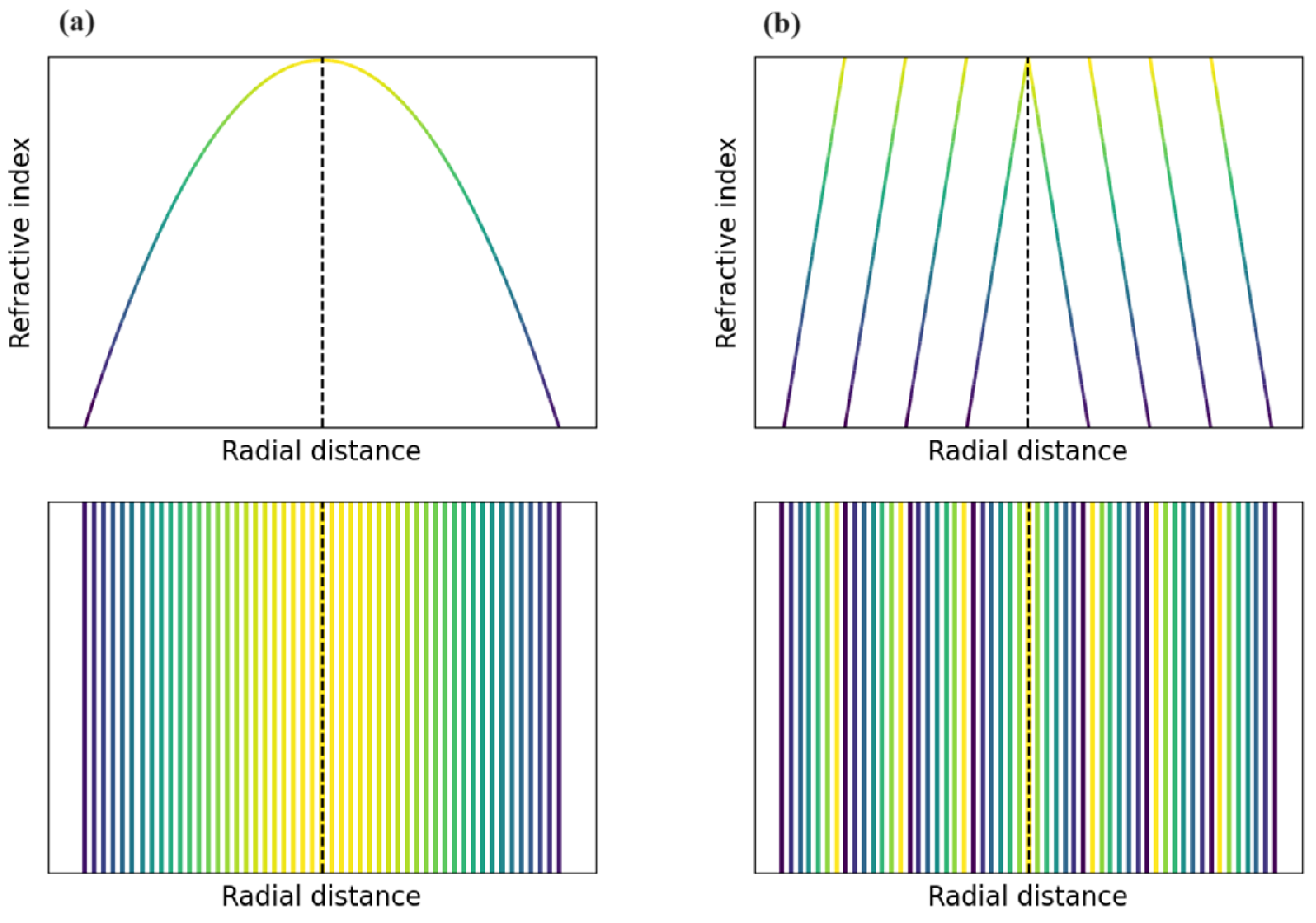
In this work, the femtosecond laser source used for the writing process is a Coherent RegA femtosecond Ti:Sapphire amplifier which has a central wavelength of 800 nm and a pulse duration of around 250 fs at a 250 kHz repetition rate. The writing power of the femtosecond laser beam is 20 mW and it was focused into the sample by a 50 mm focal length lens (Thorlabs). The distance between two channels is 2.3 μ m, while the displacement distance between two layers Δ z is 10 μ m. The Δ n value of each channel was controlled by varying τ from 10 to 100 ms in order to ensure the desired Δ n profiles. Our focus is on the fabrication of GRIN micro-lenses with controllable optical properties by modulating the writing parameters. The micro-lenses have parabolic Δ n profiles (Figure 2a). The center of all the micro-lenses was irradiated by 100 ms to have the highest Δ n and the irradiation time for the channels on the edge was 10 ms. Micro-lenses with diameters ranging from 50 to 120 μ m were fabricated to study their optical properties. In order to demonstrate the high flexibility of our technique for producing complex GRIN optical components, we also fabricated a GRIN micro-Fraxicon. The Δ n profile of the micro-Fraxicon is based on the classical Fraxicon design of Golub [37]. The micro-Fraxicon has a diameter of 120 μ m and is divided into 4 concentric rings with a constant period (Figure 2b). On each ring, the Δ n profile is linear. We also study the properties of the micro-optics with different thicknesses. To vary the thickness, the sample was polished with a step between 100 and 200 μ m.
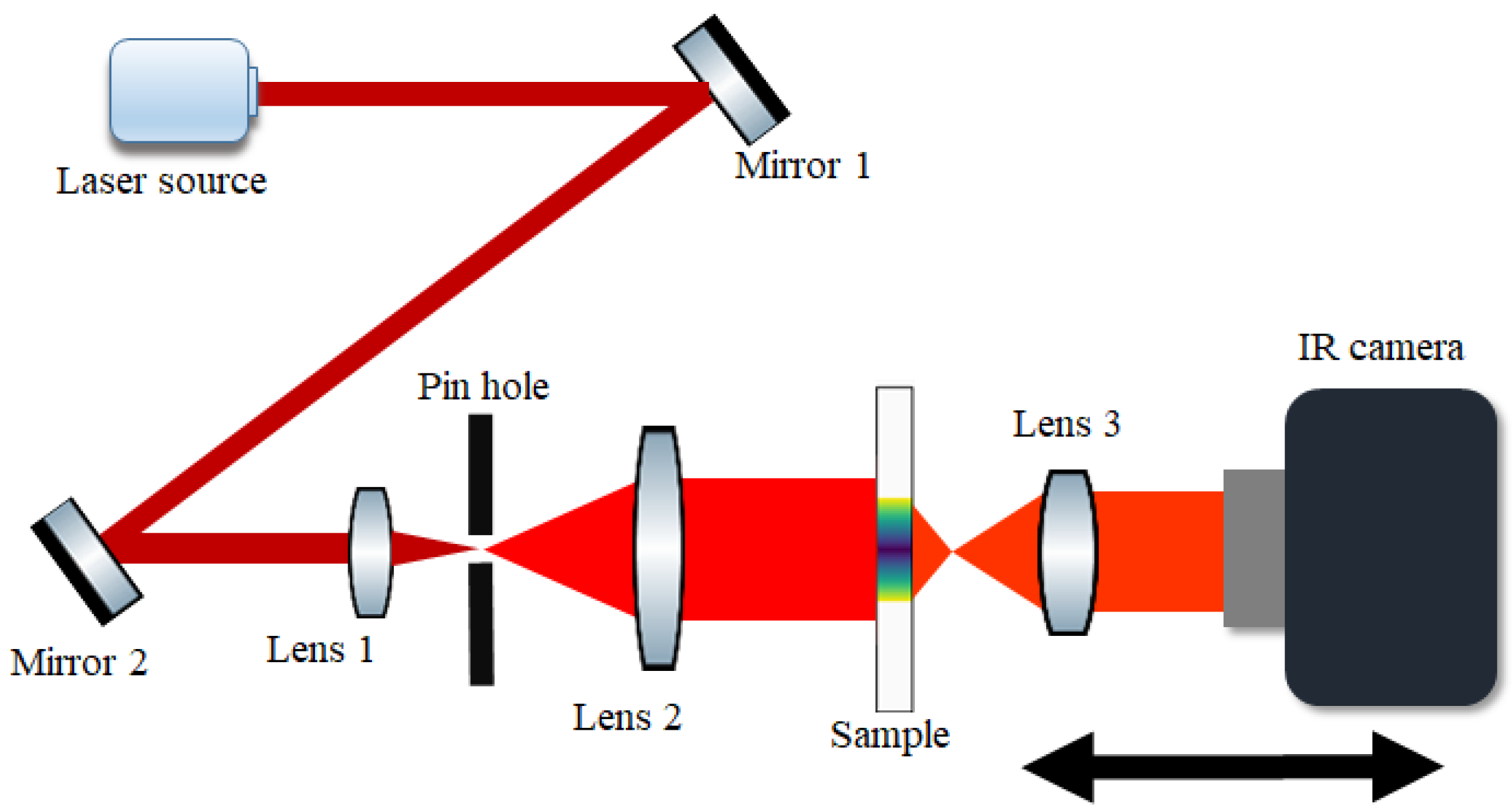
The characterization of the micro-lenses and micro-Fraxicon was performed at two different wavelengths of 2.3 μ m (diode laser, Norcada) and 4.5 μ m (quantum cascade laser, AdTech Photonics). The laser beams were spatially filtered and expanded to ensure a flat wavefront incident onto the samples. The transverse (xy plane) intensity distribution of the beam after the micro-components was imaged at different distances from the sample by an imaging system, consisting of a 5 mm focal length lens (Thorlabs) and an infrared camera (FLIR), which was mounted on X-Y translation stages (Newport). Then, the images were used to reconstruct the longitudinal (xz plane) intensity profile. The step size of the displacement was 50 μ m and the total displacement was up to 2500 μ m for the micro-lens and 5000 μ m for the micro-Fraxicon. Details of the optical setup can be found in Figure 3.
The beam propagation was also investigated numerically by using the open-source software package named PyMeep 1.20.0 [38] based on the finite-difference time-domain (FDTD) method. The beam propagation profiles were then analyzed to extract the characteristics of the optical components.

3. Results

3.1. Micro-Lenses

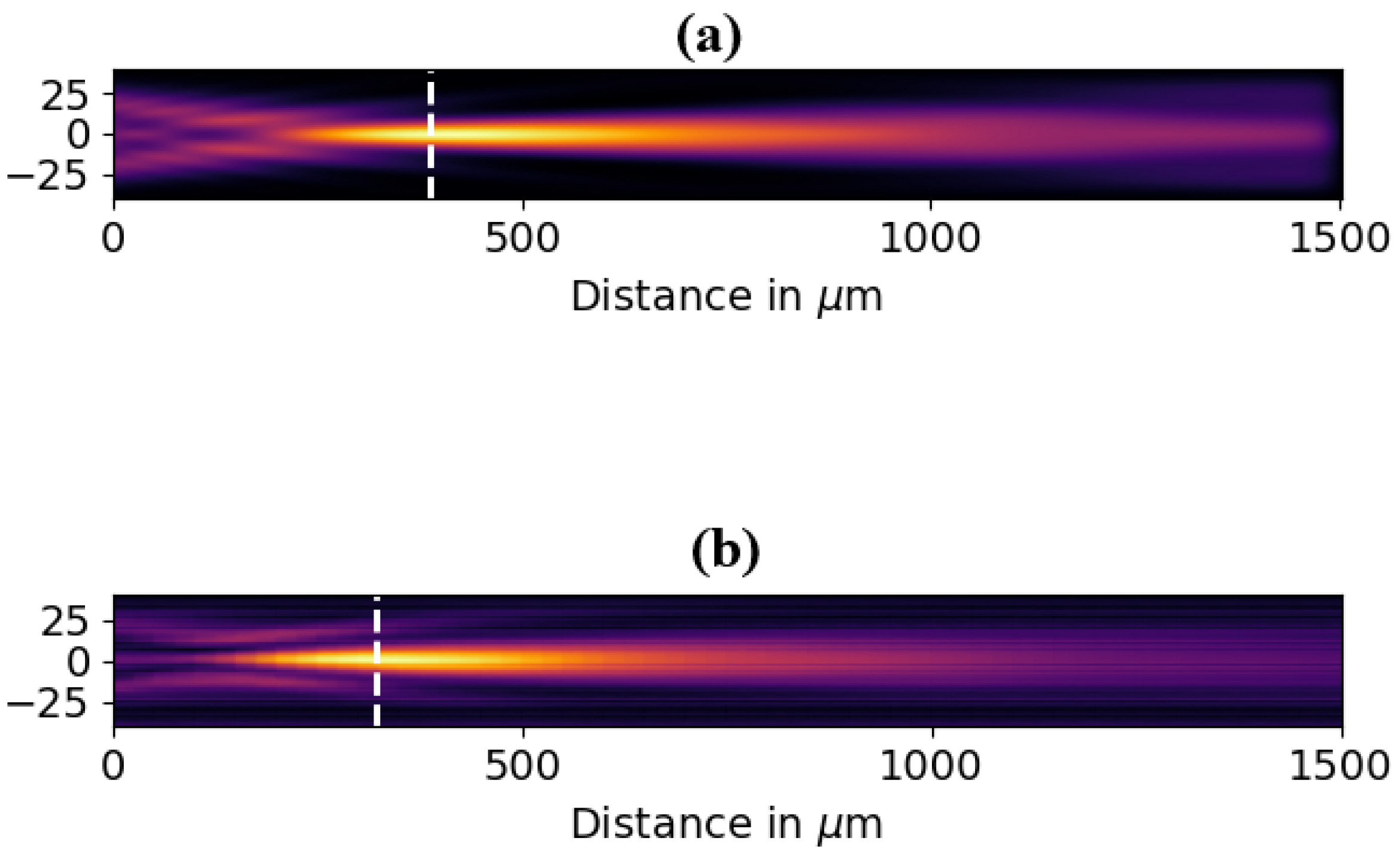
Figure 4 illustrates the experimental and simulated results of the longitudinal intensity distribution of the 2.3 μ m wavelength beam after passing through a 80 μ m diameter micro-lens with a 420 μ m thickness. It is clear from both beam profiles that the focusing behavior is demonstrated. Similar behaviors are observed for all the micro-lenses at different thicknesses and measured at a wavelength of 2.3 μ m as well as 4.5 μ m.
The focusing properties of the micro-lenses are characterized through their working distance and focal spot diameter. The focal point is defined as the point which has the maximum intensity. The working distance is defined by the distance from the surface of the micro-lens to the focal plane. The dependence of focusing properties on the diameter of micro-lens is reported in Figure 5. In this figure, the sample thickness is fixed at 420 μ m. The working distance depends strongly on the micro-lenses’ diameter, as can be observed in Figure 5a. The working distance increases more than 65 times at a wavelength of 2.3 μ m (17 μ m to ∼1150 μ m) and almost 100 times for a wavelength of 4.5 μ m (8.4 μ m to 800 μ m) when the diameter changes from 50 μ m to 120 μ m. The working distance of the small-diameter samples (50–70 μ m) are nearly the same for both wavelengths; the differences are only from 10 to around 30 μ m. This low chromatic dependence with small diameters has the potential to be applied for hyperspectral imaging. It is worth mentioning that it is possible to observe the focus on the surface of or inside thicker samples. For diameters larger than 80 μ m, the working distance is much longer when measured at a wavelength of 2.3 μ m in comparison with a wavelength of 4.5 μ m; the difference reaches approximately 350 μ m for the micro-lens of 120 μ m in diameter.
The focal spot diameters also become larger with the increase in micro-lens diameter. For the same micro-lens, the focal spot is larger at a wavelength of 4.5 μ m compared with 2.3 μ m (Figure 5b), varying from nearly 6 to around 15.5 μ m and from 3.5 to 9 μ m, respectively. It is because the beam waist is proportional to the wavelength, so the focus is tighter at a shorter wavelength. An explanation for the effects of micro-lens diameter on lens optical properties is that the Δ n spatial gradient is stronger when the diameter is smaller. This results in a larger curvature of the wavefront so that we have tighter focusing and a shorter working distance.
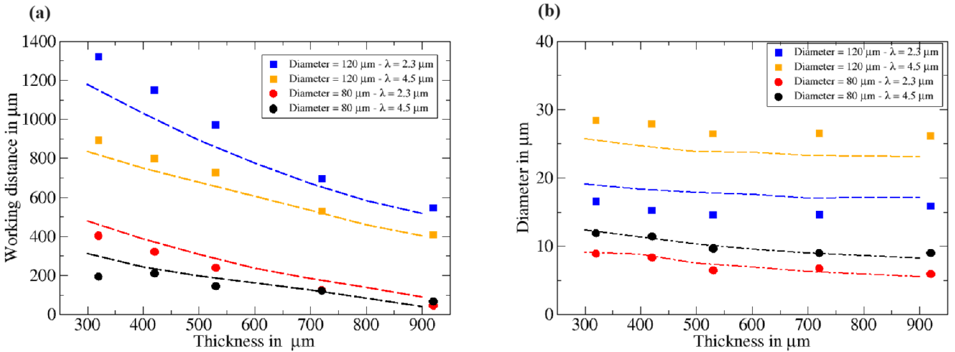
Figure 6a illustrates the relationship between the working distance and the thickness of micro-lenses. It can be easily observed that the working distance increases as the thickness decreases. Although there are small discrepancies between the simulated (the dashed lines) and experimental (the points) values for a 120 μ m diameter at thicknesses less than 600 μ m and measured at a wavelength of 4.5 μ m, the experimental data closely follow the tendency of the numerical data, and the values are almost identical for the 80 μ m diameter sample. The figure shows data for only two diameters (80 and 120 μ m), but similar results are obtained for all the diameters. This behavior can be explained by the fact that the phase difference between the beam’s center and edge, which is a function of thickness, is smaller in thinner samples. Hence, it leads to less curvature of the wavefront and a longer working distance as the thickness decreases. In contrast, the focal spot diameter seems to remain constant with the change in sample thickness, as demonstrated in Figure 6b. The beam diameter increases by only 3 μ m as the thickness decreases from 920 to 320 μ m for both 2.3 and 4.5 μ m wavelengths. The behavior was also confirmed by numerical data, as displayed by the dashed lines in Figure 6b.
The relationship between the size and optical properties of micro-lenses indicates the way in which to fabricate the micro-lenses with total control of their optical properties. By choosing the right parameters for the FLDW process, we are able to produce micro-lenses with desired properties in a single step.

3.2. Micro-Fraxicon

Figure 7a displays the beam propagation profiles of the Bessel-like beam generated by the micro-Fraxicon at a 700 μ m thickness. The result shows that the light is confined into a long focal region along the propagation direction of the beam.
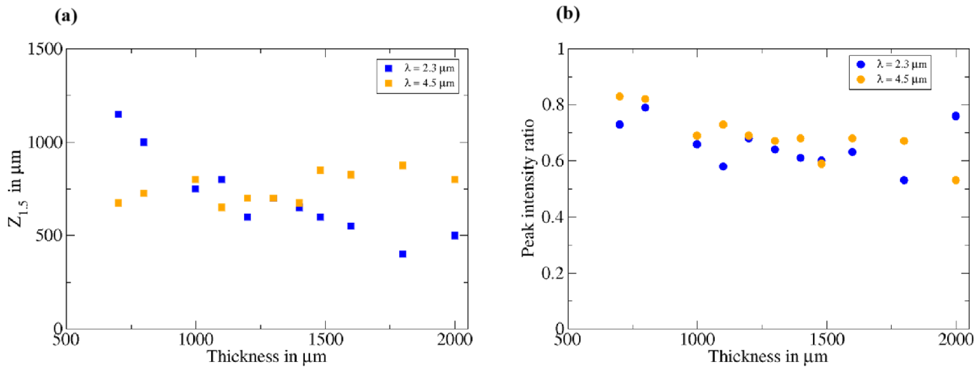
To quantify the non-diffracting property of the Bessel-like beam generated by the micro-Fraxicon, we define here a parameter called Z 1.5 , which is the distance from the position of the minimum beam waist to the position where the beam radius is 1.5 times larger than its minimum. As illustrated in Figure 7b, the distance from the line ω 0 (minimum beam waist) to the line ω 1.5 (the position has a beam radius 1.5 times larger than minimum beam waist) is the distance Z 1.5 . Z 1.5 is representative of the distance where the beam waist is nearly unchanged, and it can be considered that the beam is non-diffracting. Thus, the longer the Z 1.5 , the better the non-diffracting property of the micro-Fraxicon. The evolution of Z 1.5 with the thickness of micro-Fraxicon is shown in Figure 8a. At a wavelength of 2.3 μ m, the value of Z 1.5 increases as the sample becomes thinner and reaches approximately 1200 μ m at a sample of thickness 700 μ m. In the case of a wavelength of 4.5 μ m, the Z 1.5 value seems to be independent of thickness; the Z 1.5 is around 750 μ m for all thicknesses.
To characterize the evolution of the intensity of the beam as it propagates after the sample, we report in Figure 8b the ratio of the peak intensity of the beam at Z 1.5 to the peak intensity at the minimum beam waist for different sample thicknesses. With the thinning of the substrate, the peak intensity ratio is increased for both wavelengths, from around 0.5 at a thickness 2000 μ m to as high as 0.8 for a thickness less than 1000 μ m.
The high value of Z 1.5 and the peak intensity ratio mean that our micro-Fraxicon converts a Gaussian beam to a high quality non-diffrating Bessel-like beam.

4. Discussion

The experimental results confirm the successful fabrication of GRIN micro-lenses and micro-Fraxicons, demonstrating the capacity to precisely control the optical properties of GRIN micro-lenses by adjusting their thickness and diameter. A decrease in micro-lens thickness increases the working distance due to a reduction in the phase difference accumulated between the beam’s center and edge. Therefore, in thinner samples, the smaller phase difference results in a flatter wavefront, thus leading to a shorter working distance. Additionally, reducing the micro-lens diameter enhances the transverse Δ n gradient while keeping the Δ n difference between the center and edge constant. This stronger Δ n gradient in smaller micro-lenses leads to a larger curvature wavefront; hence, the focusing is tighter and the working distance is shorter.
In comparison to previous GRIN micro-lenses [29,39,40], our GRIN micro-lenses demonstrate high performance across a broad range of the mid-infrared region, whereas most existing designs operate in the visible and near-infrared ranges. Furthermore, the optical properties of our GRIN micro-lenses are highly adjustable, making them ideal for applications requiring precise focusing or beam expansion. The GRIN micro-Fraxicon also shows significant improvement, especially in the focal region (∼1200 μ m), compared to previously reported GRIN micro-axicons [12].
The methodology developed in this paper opens a new door for the fabrication of more complicated GRIN micro-optical components such as freeform optics or phasemasks for optical vortex beam generation. It also has potential to integrate the GRIN micro-optical components on optical fibers and photonic circuits, which could drive innovation in photonic device miniaturization.

5. Conclusions

In summary, we introduce a simple and very flexible method for producing GRIN micro-optical components in chalcogenide glass based on the femtosecond laser direct writing technique. We have demonstrated that the technique is able to locally control the refractive index of the glass, enabling complex Δ n profiles. We have proven the flexibility by fabricating GRIN micro-lenses and a micro-Fraxicon together with testing their optical properties in a broadband of the mid-infrared region. The quantitative study of the working distance and beam waist of the micro-lenses reveals the relationship between their optical properties and their diameters, as well as thickness. In addition, we have proven the generation of a Bessel-like beam using a GRIN micro-Fraxicon which was fabricated by using the same technique. The generated Bessel-like beam showed a long confinement zone along the propagation direction, with a small decrease in peak intensity.

Author Contributions

Conceptualization, P.M.; methodology, T.L.P., M.L.M., C.B.-P., D.L.C. and P.M.; software, P.M.; formal analysis, P.M. and D.L.C.; investigation, T.L.P., M.L.M., C.B.-P., P.M. and D.L.C.; data curation, T.L.P. and P.M.; writing—original draft preparation, T.L.P.; writing—review and editing, M.L.M., C.B.-P., P.M. and D.L.C.; supervision, C.B.-P., D.L.C. and P.M.; funding acquisition, P.M. and D.L.C. All authors have read and agreed to the published version of the manuscript.

Funding

This research was funded by the French Research Agency (Agence Nationale de la Recherche, ANR) under grant number ANR-22-CE08-0031 and the French Ministry of Higher Education and Research and the Région Haut de France under the project CPER WaveTech.

Institutional Review Board Statement

Not applicable.

Informed Consent Statement

Not applicable.

Data Availability Statement

The raw data supporting the conclusions of this article will be made available by the authors on reasonable request.

Acknowledgments

The authors acknowledge the financial support of the French Research Agency (Agence Nationale de la Recherche, ANR) under grant number ANR-22-CE08-0031. They also acknowledge the financial support of the French Ministry of Higher Education and Research and the Région Haut de France under the project CPER WaveTech. T.L.P also acknowledges the Université du Littoral-Côte d’Opale for the financial support of his work.

Conflicts of Interest

The authors declare no conflicts of interest.

References

  1. Zhang, X.; Hongli, M.A.; Lucas, J. A new class of infrared transmitting glass-ceramics based on controlled nucleation and growth of alkali halide in a sulphide based glass matrix. J. Non Cryst. Solids 2004, 337, 130–135. [Google Scholar] [CrossRef]
  2. Calvez, L.; Ma, H.L.; Lucas, J.; Zhang, X.H. Glasses and glass-ceramics based on GeSe2–Sb2Se3 and halides for far infrared transmission. J. Non Cryst. Solids 2008, 354, 1123–1127. [Google Scholar] [CrossRef]
  3. Li, Z.; Olah, A.; Baer, E. Micro-and nano-layered processing of new polymeric systems. Prog. Polym. Sci. 2020, 102, 101210. [Google Scholar] [CrossRef]
  4. He, C.; Chang, J.; Hu, Q.; Wang, J.; Antonello, J.; He, H.; Liu, S.; Lin, J.; Dai, B.; Elson, D.S.; et al. Complex vectorial optics through gradient index lens cascades. Nat. Commun. 2019, 10, 4264. [Google Scholar] [CrossRef] [PubMed]
  5. Beadie, G.; Shirk, J.S.; Rosenberg, A.; Lane, P.A.; Fleet, E.; Kamdar, A.R.; Jin, Y.; Ponting, M.; Kazmierczak, T.; Yang, Y.; et al. Optical properties of a bio-inspired gradient refractive index polymer lens. Opt. Express 2008, 16, 11540–11547. [Google Scholar] [CrossRef]
  6. Gomez-Reino, C.; Perez, M.V.; Bao, C.; Flores-Arias, M.T. Design of GRIN optical components for coupling and interconnects. Laser Photonics Rev. 2008, 2, 203–215. [Google Scholar] [CrossRef]
  7. Nguyen, V.; Larouche, S.; Landy, N.; Lee, J.S.; Smith, D.R. Quantitative comparison of gradient index and refractive lenses. J. Opt. Soc. Am. A 2012, 29, 2479–2496. [Google Scholar] [CrossRef]
  8. Michael, A.; Al Hafiz, A.; Puzzer, T.; Kwok, C.Y. Deposition and characterization of thick graded index SixOyFz films with low stress. Sens. Actuator A Phys. 2012, 178, 110–117. [Google Scholar] [CrossRef]
  9. Fourmentin, C.; Zhang, X.H.; Lavanant, E.; Pain, T.; Rozé, M.; Guimond, Y.; Gouttefangeas, F.; Calvez, L. IR GRIN lenses prepared by ionic exchange in chalcohalide glasses. Sci. Rep. 2021, 11, 11081. [Google Scholar] [CrossRef]
  10. Lavanant, E.; Calvez, L.; Cheviré, F.; Roze, M.; Hingant, T.; Proux, R.; Guimond, Y.; Zhang, X.H. Radial gradient refractive index (GRIN) infrared lens based on spatially resolved crystallization of chalcogenide glass. Opt. Mater. Express 2020, 10, 860–867. [Google Scholar] [CrossRef]
  11. Hudelist, F.; Buczynski, R.; Waddie, A.J.; Taghizadeh, M.R. Design and fabrication of nano-structured gradient index microlenses. Opt. Express 2009, 17, 3255–3263. [Google Scholar] [CrossRef] [PubMed]
  12. Filipkowski, A.; Piechal, B.; Pysz, D.; Stepien, R.; Waddie, A.; Taghizadeh, M.R.; Buczynski, R. Nanostructured gradient index microaxicons made by a modified stack and draw method. Opt. Lett. 2015, 40, 5200–5203. [Google Scholar] [CrossRef] [PubMed]
  13. Nguyen, H.T.; Kasztelanic, R.; Filipkowski, A.; Pysz, D.; Van Le, H.; Stepien, R.; Omatsu, T.; Krolikowski, W.; Buczynski, R. Broadband optical vortex beam generation using flat-surface nanostructured gradient index vortex phase masks. Sci. Rep. 2023, 13, 20255. [Google Scholar] [CrossRef] [PubMed]
  14. Nguyen, H.T.; Kasztelanic, R.; Pysz, D.; Van Le, H.; Stepien, R.; Omatsu, T.; Krolikowski, W.; Buczynski, R. Generation of high-order optical vortices with nanostructured phase masks. Opt. Laser Technol. 2024, 172, 110490. [Google Scholar] [CrossRef]
  15. Le Phu, T.; Le Coq, D.; Masselin, P. Waveguide fabrication with integrated coupling optic. Opt. Laser Technol. 2025, 180, 111522. [Google Scholar] [CrossRef]
  16. Bhardwaj, V.R.; Simova, E.; Rajeev, P.P.; Hnatovsky, C.; Taylor, R.S.; Rayner, D.M. Corkum, P.B. Optically produced arrays of planar nanostructures inside fused silica. Phys. Rev. Lett. 2006, 96, 057404. [Google Scholar] [CrossRef]
  17. Gross, S.; Jovanovic, N.; Sharp, A.; Ireland, M.; Lawrence, J.; Withford, M.J. Low loss mid-infrared ZBLAN waveguides for future astronomical applications. Opt. Express 2015, 23, 7946–7956. [Google Scholar] [CrossRef] [PubMed]
  18. Davis, K.M.; Miura, K.; Sugimoto, N.; Hirao, K. Writing waveguides in glass with a femtosecond laser. Opt. Lett. 1996, 21, 1729–1731. [Google Scholar] [CrossRef]
  19. Tan, D.; Sharafudeen, K.N.; Yue, Y.; Qiu, J. Femtosecond laser induced phenomena in transparent solid materials: Fundamentals and applications. Prog. Mater. Sci. 2016, 76, 154–228. [Google Scholar] [CrossRef]
  20. Masselin, P.; Le Coq, D.; Cuisset, A.; Bychkov, E. Spatially resolved Raman analysis of laser induced refractive index variation in chalcogenide glass. Opt. Mater. Express 2012, 2, 1768–1775. [Google Scholar] [CrossRef]
  21. Minoshima, K.; Kowalevicz, A.M.; Hartl, I.; Ippen, E.P.; Fujimoto, J.G. Photonic device fabrication in glass by use of nonlinear materials processing with a femtosecond laser oscillator. Opt. Lett. 2001, 26, 1516–1518. [Google Scholar] [CrossRef] [PubMed]
  22. Dias, A.; Muñoz, F.; Alvarez, A.; Moreno-Zárate, P.; Atienzar, J.; Urbieta, A.; Fernandez, P.; Pardo, M.; Serna, R.; Solis, J. Femtosecond laser writing of photonic devices in borate glasses compositionally designed to be laser writable. Opt. Lett. 2018, 43, 2523–2526. [Google Scholar] [CrossRef] [PubMed]
  23. del Hoyo, J.; Vazquez, R.M.; Sotillo, B.; Fernandez, T.T.; Siegel, J.; Fernández, P.; Osellame, R.; Solis, J. Control of waveguide properties by tuning femtosecond laser induced compositional changes. Appl. Phys. Lett. 2014, 105, 131101. [Google Scholar] [CrossRef]
  24. Macias-Montero, M.; Dias, A.; Sotillo, B.; Moreno-Zárate, P.; Ariza, R.; Fernandez, P.; Solis, J. Waveguide tapers fabrication by femtosecond laser induced element redistribution in glass. J. Light. Technol. 2020, 38, 6578–6583. [Google Scholar] [CrossRef]
  25. Lapointe, J.; Bérubé, J.P.; Ledemi, Y.; Dupont, A.; Fortin, V.; Messaddeq, Y.; Vallée, R. Nonlinear increase, invisibility, and sign inversion of a localized fs-laser-induced refractive index change in crystals and glasses. Light Sci. Appl. 2020, 9, 64. [Google Scholar] [CrossRef] [PubMed]
  26. Masselin, P.; Bychkov, E.; Le Coq, D. Ultrafast laser inscription of high-performance mid-infrared waveguides in chalcogenide glass. IEEE Photon. 2018, 30, 2123–2126. [Google Scholar] [CrossRef]
  27. Tan, D.; Wang, Z.; Xu, B.; Qiu, J. Photonic circuits written by femtosecond laser in glass: Improved fabrication and recent progress in photonic devices. Adv. Photonics 2021, 3, 024002. [Google Scholar] [CrossRef]
  28. Tang, H.; Di Franco, C.; Shi, Z.Y.; He, T.S.; Feng, Z.; Gao, J.; Sun, K.; Li, Z.M.; Jiao, Z.Q.; Wang, T.Y.; et al. Experimental quantum fast hitting on hexagonal graphs. Nat. Photonics 2018, 12, 754–758. [Google Scholar] [CrossRef]
  29. Delullier, P.; Druart, G.; De La Barrière, F.; Calvez, L.; Lancry, M. Femtosecond laser direct writing of gradient index fresnel lens in GeS2-based chalcogenide glass for imaging applications. Appl. Sci. 2022, 12, 4490. [Google Scholar] [CrossRef]
  30. Stankevič, V.; Karosas, J.; Gečys, P. Fabrication of a multilevel Fresnel axicon deep in fused silica by femtosecond laser machining. Opt. Lett. 2023, 48, 4404–4407. [Google Scholar] [CrossRef]
  31. Zakery, A.; Elliott, S.R. Optical properties and applications of chalcogenide glasses: A review. J. Non-Cryst. Solids 2003, 330, 1–12. [Google Scholar] [CrossRef]
  32. DeCorby, R.G.; Ponnampalam, N.; Pai, M.M.; Nguyen, H.T.; Dwivedi, P.K.; Clement, T.J.; Haugen, C.J.; McMullin, J.N.; Kasap, S.O. High index contrast waveguides in chalcogenide glass and polymer. IEEE J. Sel. Top. Quantum Electron. 2005, 11, 539–546. [Google Scholar] [CrossRef]
  33. D’Amico, C.; Martin, G.; Troles, J.; Cheng, G.; Stoian, R. Multiscale Laser Written Photonic Structures in Bulk Chalcogenide Glasses for Infrared Light Transport and Extraction. Photonics 2021, 8, 211. [Google Scholar] [CrossRef]
  34. Masselin, P.; Le Coq, D.; Calvez, L.; Petracovschi, E.; Lépine, E.; Bychkov, E.; Zhang, X. CsCl effect on the optical properties of the 80GeS2–20Ga2S3 base glass. Appl. Phys. A 2012, 106, 697–702. [Google Scholar] [CrossRef]
  35. Roberts, A.; Ampem-Lassen, E.; Barty, A.; Nugent, K.A.; Baxter, G.W.; Dragomir, N.M.; Huntington, S.T. Refractive-index profiling of optical fibers with axial symmetry by use of quantitative phase microscopy. Opt. Lett. 2002, 27, 2061–2063. [Google Scholar] [CrossRef]
  36. Ampem-Lassen, E.; Huntington, S.T.; Dragomir, N.M.; Nugent, K.A.; Roberts, A. Refractive index profiling of axially symmetric optical fibers: A new technique. Opt. Express 2005, 13, 3277–3282. [Google Scholar] [CrossRef]
  37. Golub, I. Fresnel axicon. Opt. Lett. 2006, 31, 1890–1892. [Google Scholar] [CrossRef] [PubMed]
  38. Oskooi, A.F.; Roundy, D.; Ibanescu, M.; Bermel, P.; Joannopoulos, J.D.; Johnson, S.G. MEEP: A flexible free-software package for electromagnetic simulations by the FDTD method. Comput. Phys. Commun. 2010, 181, 687–702. [Google Scholar] [CrossRef]
  39. Hudelist, F.; Nowosielski, J.M.; Buczynski, R.; Waddie, A.J.; Taghizadeh, M.R. Nanostructured elliptical gradient-index microlenses. Opt. Lett. 2010, 35, 130–132. [Google Scholar] [CrossRef]
  40. Buczynski, R.; Filipkowski, A.; Piechal, B.; Nguyen, H.T.; Pysz, D.; Stepien, R.; Waddie, A.; Taghizadeh, M.R.; Klimczak, M.; Kasztelanic, R. Achromatic nanostructured gradient index microlenses. Opt. Express 2019, 27, 9588–9600. [Google Scholar] [CrossRef]
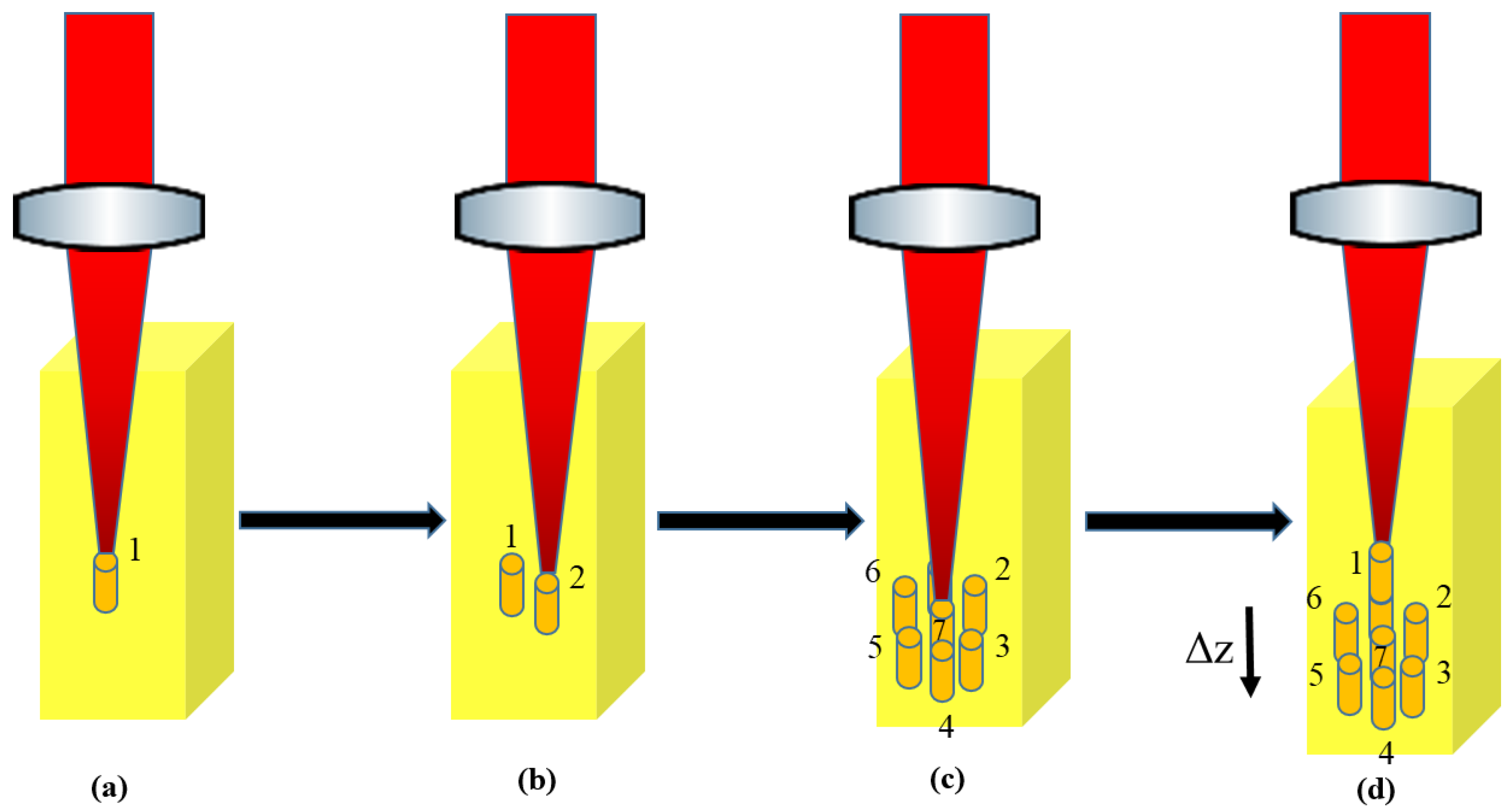
Figure 1. A scheme of the laser fabrication process. First, the laser irradiates position 1 (a), and then the other positions on the same horizontal plane are in turn irradiated to complete a layer of the optical components (b,c). After that, the sample is displaced downward by distance Δ z and the sample is translated back to channel 1 (d). The previous process is repeated until the total displacement is reached.
Photonics 11 01076 g001
Figure 2. Refractive index profile (top) and scheme of axial cross-section (bottom) of (a) GRIN micro-lens and (b) GRIN micro-Fraxicon.
Photonics 11 01076 g002
Figure 3. A scheme of the optical setup of the beam propagation measurement. Two mirrors direct the laser beam to a spatial filter which included lens 1 (25 mm focal length, Thorlabs), a pinhole (50 μ m diameter, Thorlabs), and lens 2 (50 mm focal length, Thorlabs). Lens 3 (5 mm focal length, Thorlabs) is the imaging lens which collected and projected the image on the infrared camera (A6750SC, FLIR). Len 3 and camera were mounted on X-Y translation stages (XMS160-S, Newport).
Photonics 11 01076 g003
Figure 4. (a) Simulated and (b) experimental beam propagation profiles of 80 μ m diameter micro-lens with 420 μ m thickness, measured at 2.3 μ m wavelength. Origin corresponds to sample surface. Dashed lines represent focal plane of lens.
Photonics 11 01076 g004
Figure 5. Dependence of (a) working distance and (b) focal spot diameter with thickness of 420 μ m on micro-lens diameter.
Photonics 11 01076 g005
Figure 6. Dependence of (a) working distance and (b) focal spot diameter on thickness of micro-lenses. Dashed lines are results from simulation; points are from experimental measurements.
Photonics 11 01076 g006
Figure 7. (a) Beam propagation profile, (b) beam radius evolution (red line), and longitudinal intensity profile (blue line) of micro-Fraxicon of 700 μ m in thickness measured at a 2.3 μ m wavelength. The line ω 0 marks the minimum beam waist position, whereas the line ω 1.5 is the position where the beam radius is 1.5 times larger than the beam waist at ω 0 . The origin corresponds to the sample surface.
Photonics 11 01076 g007
Figure 8. Dependence of (a) Z 1.5 and (b) peak intensity ratio on thickness.
Photonics 11 01076 g008
Disclaimer/Publisher’s Note: The statements, opinions and data contained in all publications are solely those of the individual author(s) and contributor(s) and not of MDPI and/or the editor(s). MDPI and/or the editor(s) disclaim responsibility for any injury to people or property resulting from any ideas, methods, instructions or products referred to in the content.