Article

Thermal Analysis of Acousto-Optic Modulators and Its Influence on Ultra-Stable Lasers

1
Taiji Laboratory for Gravitational Wave Universe, School of Physics and Photoelectronic Engineering, Hangzhou Institute for Advanced Study, University of Chinese Academy of Sciences, Hangzhou 310024, China
2
Key Laboratory of Space Active Opto-Electronics Technology, Shanghai Institute of Technical Physics, Chinese Academy of Sciences, Shanghai 200083, China
3
School of Physical Sciences, University of Chinese Academy of Sciences, Beijing 100049, China
*
Authors to whom correspondence should be addressed.
Photonics 2024, 11(11), 1077; https://doi.org/10.3390/photonics11111077
Submission received: 29 September 2024 / Revised: 8 November 2024 / Accepted: 12 November 2024 / Published: 15 November 2024
(This article belongs to the Section Lasers, Light Sources and Sensors)

Abstract

:
Acousto-optic modulators (AOMs) have been widely used in ultra-stable lasers (USLs) for optimizing its performances. A thermal theoretical model of the AOM, which is made by TeO2, was established. Based on the model, the temperature coefficients of the diffraction angle and efficiency were calculated to be 4.051 μrad/°C and 0.018%/°C. The influences of thermal effects of the AOM on USLs’ cavity coupling and frequency stability were firstly studied. A 1 °C temperature change in the AOM results in a 0.31 Hz frequency fluctuation of the laser within the USL cavity. Simulation and experimental results indicate that, to achieve USLs’ optimal performance, thermal effects of AOMs within the system must be addressed and managed.

1. Introduction

Ultra-stable lasers (USLs) are gaining significance due to the rising demand for precision measurements [1,2,3,4]. Power and frequency stability are critical parameters for USLs, influenced by the laser’s internal complexity as well as environmental factors [5,6,7,8,9]. To optimize these parameters, an acousto-optic modulator (AOM) has been applied to USLs.
Previous studies have demonstrated that fluctuations in the power of the incoming cavity beam can result in a frequency jitter of the laser. One approach to enhance frequency stability is to utilize the fast response characteristics of the AOM to control the diffracted beam intensity of the AOM through a feedback system, thus controlling the power stabilization in front of the cavity [10,11,12,13]. When an AOM is used as a power stabilization device in ultra-stable lasers, combined with mode-cleaning techniques, it can reduce relative intensity noise (RIN) to the 10−8–10−9 range in the 1 Hz to 1 kHz frequency band [14,15]. A USL serves as a frequency reference for transmission, necessitating the ability to transmit over long distances via optical fiber. However, it introduces phase noise into the USLs. Dynamic suppression of the phase noise is achieved through round-trip optical fiber and phase-locked loop modulation of the AOM input signal, facilitating the generation of a high-precision optical frequency standard for long-distance transmission [16,17]. In certain specific applications, such as optical atomic clocks, the USL must be accurately locked to the specific atomic leap spectral line frequency. The output frequency of the USL is controlled by the frequency of the AOM input signal [18,19,20]. These studies demonstrate that the application of AOMs in USLs enhances their performance and ensures the feasibility of various application scenarios. However, as an active device, the AOM generates significant heat and temperature fluctuations during operation, affecting its operational state and performance parameters [21,22,23,24]. In previous studies, the temperature characteristics of USLs were mainly focused on the precision temperature control of the optical cavity [25,26], and the mechanism of the AOM thermal effect on the USLs has not been analyzed in detail. Therefore, it is essential to study and analyze the temperature characteristics of AOMs within USLs to explore their impact on USL performance.
In the present work, influences of thermal characteristics of the AOM on the USLs were studied. The temperature response of the AOM with TeO2 as the working crystal was theoretically calculated. Furthermore, an angular change model for the first-order diffracted beam of the AOM was developed through a combination of practical tests. This work explores the impact of temperature characteristics of the AOM on the performance of the USL, specifically regarding the AOM’s effect on power stability and the influence of the cavity on frequency stability. To suppress the effects of temperature on USLs performance, a double-pass scheme based on active temperature control was proposed. This scheme provides an optimized reference for the spatial application of USLs.

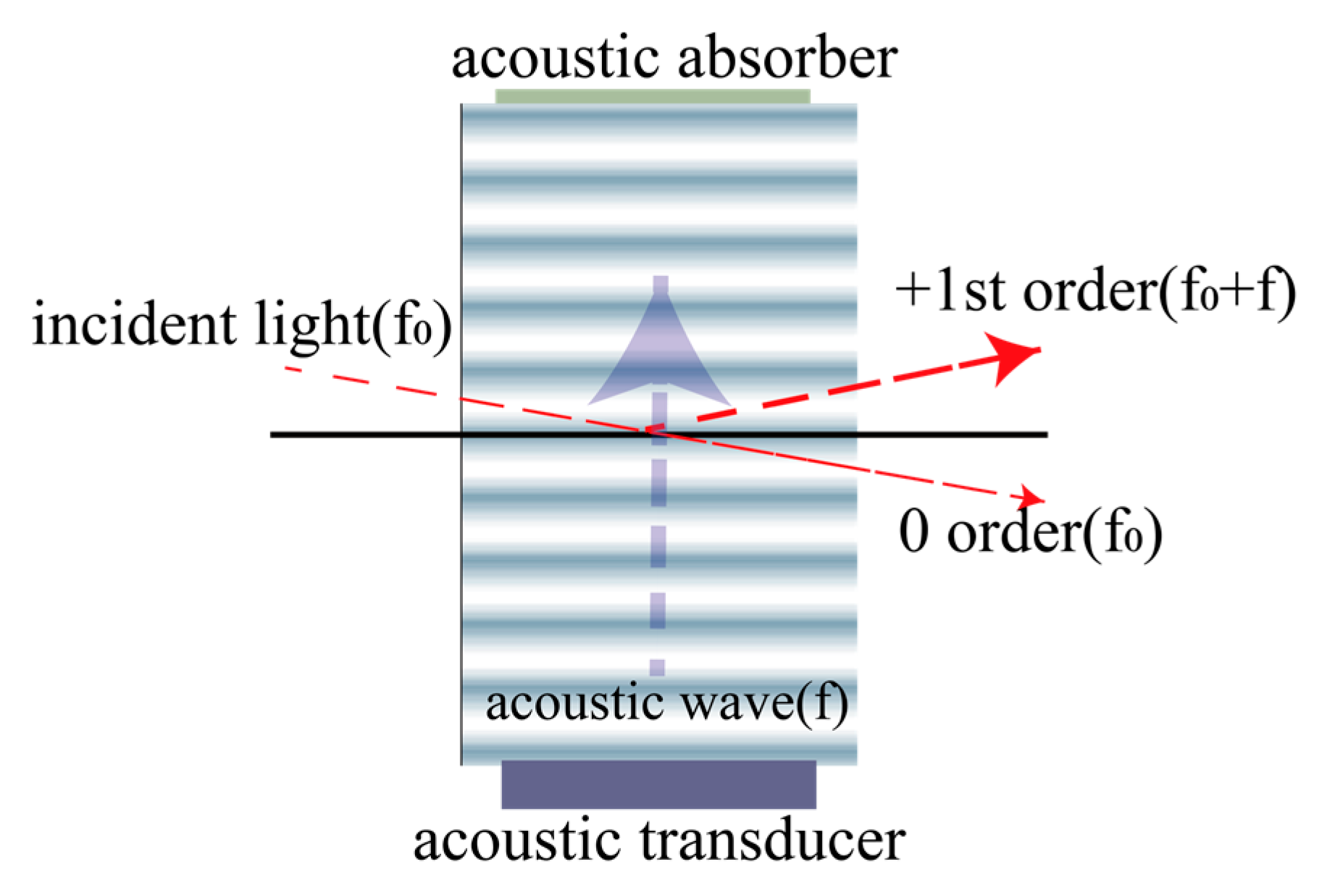
2. Theory and Simulation

As shown in Figure 1, an AOM is composed of an acoustic-optic crystal, a piezoelectric transducer, a sound absorber and radio frequency (RF) impedance matching electronics. When a high power (watt level) RF signal is applied on the piezoelectric transducer, sound waves are generated. Due to the photo-elastic effect, the refractive index of the crystal is altered by the oscillating mechanical strain of sound waves. Since sound waves are transmitting in the crystal, an equivalent optical grating is formed inside the crystal. Consequently, when a laser beam passes through an AOM, it will be diffracted into different orders. The intensity, frequency and spatial direction of diffracted higher-order laser beams will be modulated.
When an RF signal is applied on the AOM, the temperature of the AOM increases due to heat accumulation. This heat accumulation can be attributed to several factors. When high-frequency electrical power is applied to the piezoelectric transducer of the AOM, not all of the electrical power is converted into sound energy due to electromechanical conversion. Part of the electric power is absorbed by the atoms in the piezoelectric element and converted into heat. Simultaneously, as sound wave propagates through the optical medium, a portion of the energy is absorbed into the internal energy of the acousto-optic interaction medium. This phenomenon of heat absorption is also observed in the acoustic absorber. When the acoustic wave is absorbed by the acoustic absorber as it travels to the far end of the crystal, a portion of the energy will then be converted to heat.
To characterize the influence of heat accumulation on the performance of AOM, a theoretical model was established as follows. The expression of the Bragg diffraction angle is the following [27]:
s i n θ B r a g g = λ 2 Λ
where λ is the wavelength of the incident beam in a medium, and Λ is the wavelength of the sound wave. λ is related to n , the refractive index of acousto-optic crystals. Λ is related to the frequency of the sound wave, and V a is the speed of propagation of the sound wave in a medium. In a Bragg diffraction, the frequency of the sound wave in the crystal is equal to the frequency of the input RF signal. The parameters n and V a are temperature-dependent. The correlation between V a and temperature is due to the crystal elasticity coefficient versus temperature. Substituting into the above equation allows the Bragg diffraction angle to be expressed as a temperature-dependent function
θ B r a g g ( T ) = a r c s i n λ 0 2 n ( T ) V a ( T ) f
where λ 0 is the wavelength of the incident beam in a vacuum, and λ 0 is set to 1064 nm; T is the temperature of the crystal from 15 °C to 50 °C; n is the effective refractive index of the acoustic crystal, and n = 2.220702 × ( 1 + 6.01 × 10 6 T ) ; V a is the propagation speed of sound waves in the acousto-optical crystal, V a = 657.1 0.0767 × ( T 20 )   [28]; and f is the operating center frequency of the AOM set to 100 MHz. After bringing in the parameters of TeO2 [29,30,31], the relationship between the crystal temperature and diffraction angle is calculated to be linear with a coefficient of variation as 4.051 μrad/°C, as shown in Figure 2.
Changes in crystal temperature also have an effect on diffraction efficiency. The efficiency of the diffracted beam at the first order of the AOM can be expressed as the following equation [32]:
η = s i n 2 π λ M 2 L P a 2 H
where L , H are the length and width of the piezoelectric transducer, respectively, and P a is the sound power in the acousto-optic interaction region. The acousto-optic figure of merit is an important descriptive parameter of the acousto-optic crystal and is closely related to the diffraction efficiency of the acousto-optic crystal, which can be described by the following equation [33]:
M 2 = n 6 p 2 ρ V a 3
where n is the effective refractive index of acoustic crystal; p is photo-elasticity coefficient, p = 0.34; ρ is the density of TeO2, ρ = 5966.679 ( 0.1832704 T ) ( 1.512033 4 T ) 2 ; and V a is the propagation speed of sound waves in the TeO2. Therefore, the primary diffracted optical power can be expressed as the following equation:
η B r a g g ( T ) = s i n 2 π p n ( T ) 3 λ V a ( T ) L P a ρ ( T ) V a ( T ) 2 H
The relationship between crystal temperature and diffraction efficiency is linear with a coefficient of variation of 0.018% per degree Celsius, as shown in Figure 3.
Temperature-induced changes in the operating state of the AOM can have an impact on the performance of ultra-stable lasers. By using the above equation, it can be concluded that the variation in both the diffraction angle and the diffraction efficiency is approximately linear. The temperature variation coefficient for diffraction efficiency is low, and the magnitude of change is significantly smaller than the power fluctuation range of the laser itself, meaning that temperature-induced power changes may be obscured by laser intensity noise in practical tests. Thus, it does not need to be considered separately in the laser power feedback control.
However, a change in the diffraction angle will have an effect on the laser entering cavity. In general, the USLs have two methods for the beam to enter the cavity after passing the AOM: spatial optical direct coupling and fiber coupling into the FP cavity. The AOM affects both ways of entering the cavity. In the case of a spatially coupled cavity, the heat generated by the AOM causes an angular drift of the diffracted beam, which changes both the angle and the position of laser incidence into the cavity, introducing a cavity mismatch. Referring to the previous study on the cavity mode and incidence angle [34,35], the distribution of laser modes in the cavity is also changed. A 100 mm cubic flat-concave FP cavity used in the laboratory is taken as an example of parameter input (see Table 1 for the parameters), and the scanning in a free spectral range (FSR) of the cavity is simulated to solve the mode distribution due to the angular drift and decentration of the diffracted light at different temperatures of the AOM.
The simulation results are shown in Figure 4. It shows that, on the basis of the already matched in-cavity optical path, the change in AOM temperature decreases the intensity of the TEM00 mode. Moreover, the temperature sensitivity of the system is positively correlated with the reflectivity of the cavity mirror, which means the higher the fineness of the cavity, the faster the intensity of the TEM00 mode decreases. When the cavity mirror reflectivity is 99.95%, a temperature fluctuation of 17.69 °C results in the TEM00 mode intensity decreasing to 50% of its original value, causing it to lose its dominance. When the cavity mirror reflectivity reaches 99.99%, the temperature fluctuates only 5.85 °C, and the TEM00 mode intensity decreases to 50% of the original. This situation leads to a lower amplitude and a shallower slope of the error signal during the locking process of the USLs, thereby affecting the locking accuracy and potentially resulting in false locking. Achieving higher frequency stabilization performance requires higher precision control of the AOM temperature, as the higher the stability required for USLs, the higher the fineness of the cavity used.
The fiber-coupled cavity mode can effectively avoid mode changes caused by incident angles. However, the angular drift of diffraction can cause changes in the optical path, leading to a decrease in coupling efficiency and ultimately a decrease in cavity power. Due to the high fineness of the cavity used in the USL, its thermal effect is obvious. The fluctuation of the in-cavity power will lead to a change in the equivalent length of the cavity and the corresponding drift of the locked laser frequency. The thermal noise limit of a 100 mm cubic cavity is better than 1 × 10⁻¹⁵ [36]. To make the performance of the USLs close to the thermal noise limit, when the in-cavity laser is about 40 μW, the fractional stability of the in-cavity laser power is required to reach the 10−4 level, and the suppression of the AOM temperature effect is necessary.

3. Temperature Effect Verification Experiment

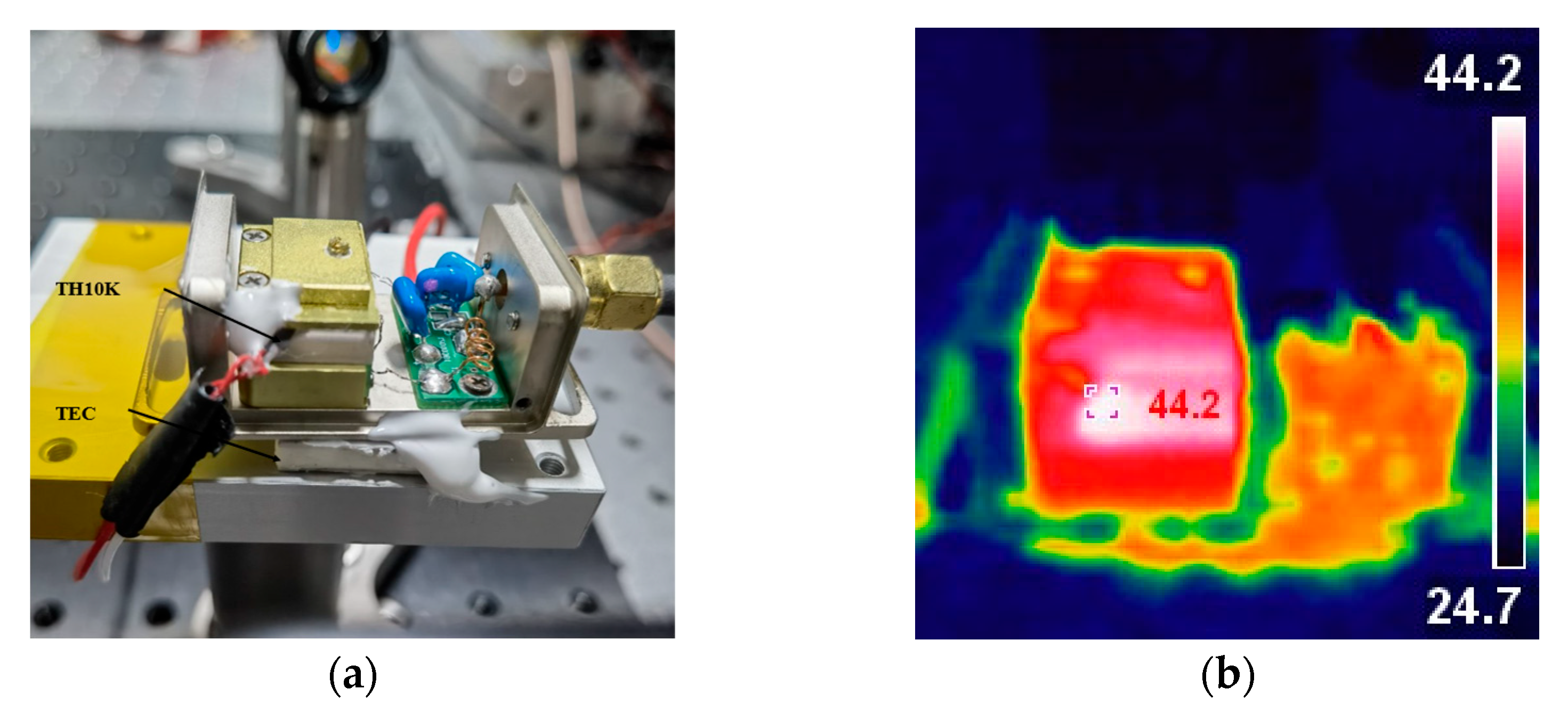
3.1. Heat Generation and Analysis

By changing the laser incident power and RF signal power, the AOM operating temperature profile was tested to verify the factors affecting the AOM temperature change, respectively. The AOM used in this work was of the 26th Research Institute of China Electronics Technology Group with the model number of SGT100-1064-1.5 TA (Chengdu, China). The AOM used TeO2 as its internal crystal and operates in the Bragg diffraction range. Theoretically, the first-order efficiency in Bragg diffraction can reach 100% because precise phase matching and optimal interaction length enable complete, coherent energy transfer from the incident light to the first-order diffracted beam. However, in practice, the AOM experienced some loss of diffraction efficiency. After conducting experiments at a wavelength of 1064 nm and a frequency shift of 100 MHz, the diffraction efficiency was found to reach 85%. The SMA cables connected to the AOM in the figure were also grounded, sharing a common ground with the entire optical platform to mitigate external signal. The heat generation power of the AOM in working condition is about 2 W. The TH10K is the temperature sensor for the crystal. It was coated with thermally conductive silicone grease and placed on the side of the crystal. The sensor was then fixed with silicone rubber. The TEC is positioned under the AOM and connected to the Vescent SLICE-QTC (Vescent, Golden, CO, USA) temperature controller, as shown in Figure 5a. The internal structure was photographed using an infrared thermal imager while the AOM was in operation, as shown in Figure 5b. The higher temperatures were on the left side of the crystal, and the circuitry on the right was also heating up. Where there is a clear temperature gradient inside the crystal, the image shows the highest temperature at the side edges of the crystal, which should be caused by the heat release from the acoustic absorber.
Firstly, the temperature change in the crystal was measured at a step interval of 30 mW when a laser beam with a power of 0–150 mW incident on the AOM, as shown in Figure 6a. During the 10 min test period, the temperature fluctuated around 1 °C, with no significant temperature rise. Such temperature fluctuations are caused by changes in room temperature, so the temperature changes caused by laser absorption within the crystal can be ignored. After experimental verification, it was determined that the USL system normally is capable of producing a beam within 100 mW of the incident beam. The absorption of the beam by the crystal temperature of the impact can be ignored.
The crystal’s temperature was 21.4 °C before the AOM was activated, which is similar to the room temperature of the laboratory, which was 22 °C with 37% humidity. Without temperature control measures, the crystal’s temperature rapidly increases for the first 5 min after work begins. The growth rate then gradually slows down until it reaches a temperature equilibrium state. The temperature at equilibrium is mainly dependent on the power of the RF signal. To generate the signal, a signal generator was used at a frequency of 100 MHz with intensities of 30 dBm, 30.5 dBm, and 31 dBm for sinusoidal signals. The final equilibrium temperatures are 42 °C, 45 °C, and 47 °C, respectively. Figure 6b shows the changes in crystal temperature during the startup process.

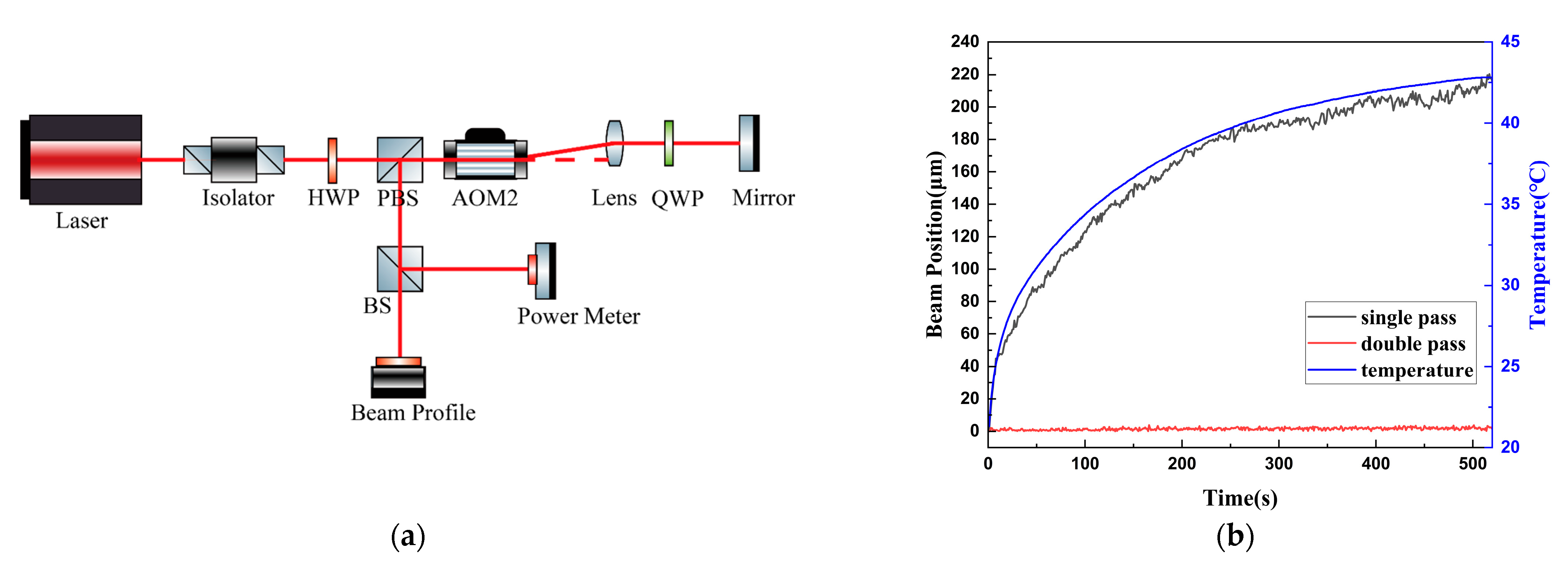
3.2. Diffraction Angle Shift for Single Pass

The diffraction angle temperature model for AOM primary diffracted light was tested. To avoid the influence of other active devices in the USL, a simplified verification experiment was conducted separately. Figure 7a shows the 1064 nm NPRO laser source incident on the AOM through a fiber collimator. The polarization direction was adjusted by a λ/2 plate. The beam was divided into two paths by an intensity beam splitter. One path was used for power detection, and the other was used for spot position capture. The length of the path was increased to 1.5 m before entering the camera. The first order diffracted optical power was recorded using a Thorlabs power meter PM100D (Newton, MA, USA), and the first-order diffracted spot position was recorded using a Thorlabs beam analyzer BC106N-VIS/M (Newton, MA, USA), as shown in Figure 7b. The diffraction efficiency was calculated using the Thorlabs power meter. The spot position data collected by the beam profiler were linearly fitted to solve for the rate of change in the position relative to the temperature, and the beam position was fitted to the curve as x = 10.23T − 226.88. The change in the diffraction angle was calculated as 6.82 μrad/°C.

3.3. Diffraction Angle Shift for Double Pass

The experimentally measured diffraction angle temperature sensitivity is similar to the simulation result of 4.051 μrad/°C, which is also in accordance with the linear approximation, and, therefore, the simulation model is valid. The reasons for the numerical discrepancy may be as follows: firstly, due to the limitation of the AOM structure, the temperature measurement position can only be located at the side of the crystal, and there is a gradient in the heat distribution of the crystal, which leads to the discrepancy between the measured temperature and the temperature of the crystal at the position where the actual diffraction of the beam occurs. Secondly, the heat release from the absorber was neglected in the experiment; it will have a slight effect on the sound velocity in the crystal. In addition, the temperature dependence of the speed of sound in the model did not take into account that the temperature dependence of the photo-elastic coefficient may introduce errors. There may also be errors in the individual devices themselves that cause the propagation direction of the sound wave to be at an angle to the ideal crystal plane direction and thus affect the sound velocity.
To address issues caused by variations in diffraction angle, an optical feedback design can be introduced [37]. In this system, the light returns via a mirror and passes through the AOM again, making a total of two passes through the same AOM. In the following sections, this feedback light path will be referred to as the double-pass configuration. Figure 8a shows the specific double-pass optical path design based on the AOM. After emission, the laser first passed through a half-wave plate (λ/2) to adjust the polarization direction, maximizing the transmitted intensity through a polarizing beam splitter (PBS), and then it entered the AOM. The angle of incidence on the AOM was adjusted to achieve maximum first-order diffraction intensity. The beam exiting the AOM then passed through an optical system composed of a quarter-wave plate (λ/4) and a cat’s-eye lens with a focal length of 40 mm, which focused the beam perpendicularly onto a mirror. The quarter-wave plate rotated the polarization of the reflected light by 90° relative to the incident beam, allowing it to pass through the AOM again. At the PBS, the optical path was deflected by 90°, separating the incident and diffracted beams. The cat’s-eye system, consisting of the lens and the mirror at its focal plane, ensured precise overlap between the incident and return paths. Adjust the mirror’s direction to ensure that the beam as perpendicular to the incident beam. This action will result in the highest possible diffraction efficiency, which can reach up to 70%. The double-pass AOM optical path was used to perform dynamic temperature experiments. The primary diffracted optical power and spot position were recorded separately. The total diffraction efficiency is the product of the two diffraction efficiencies due to the two passes of the AOM. The power of the diffracted beam was reduced from 20 mW to 12 mW. The experiment shows a significant reduction in the diffraction angle when compared to a single pass of the AOM within the same temperature fluctuation range. The initial spot position was noted as 0, the maximum range of the diffracted beam shift was reduced from 220.39 μm to 4.65 μm, and the shifts in the double diffraction angles in both directions were only 2.1% of that of the single diffraction, as Figure 8b shows. The double-pass AOM diffraction angle should theoretically remain constant regardless of temperature. Any detected changes in position during experimentation are likely due to mounting errors. Additionally, the optical power remained stable after being coupled by the fiber coupler.
The experiment comparing the temperature characteristics of the single-pass AOM and double-pass AOM shows that the double-pass AOM scheme can effectively reduce the temperature sensitivity of the AOM diffraction angle drift. However, it results in a larger power loss. In scenarios where laser power loss is not a concern, power fluctuations can be monitored using PD and then controlled through a feedback system for the closed-loop control of RF signal strength. In practical applications of USLs, the double pass AOM program’s active feedback control of the temperature control system is an effective solution to the dynamic temperature response introduced in the AOM work.

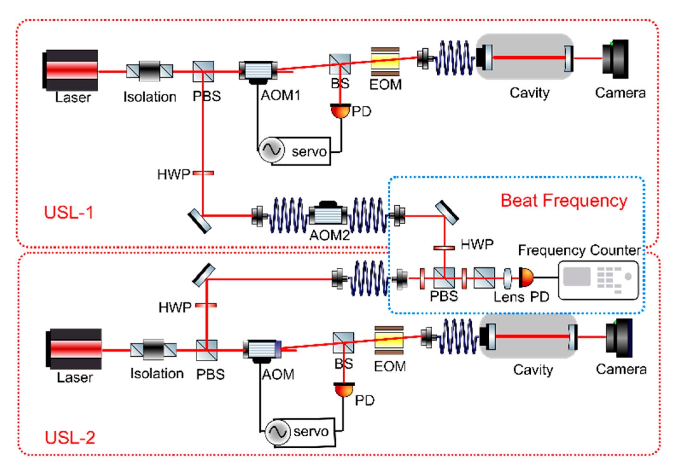
4. Influence and Analysis of AOM on Laser Frequency Stability

The primary performance metric for USLs is frequency fractional stability. Therefore, when using the AOM in USLs, it is crucial to consider its temperature effects on laser frequency. The modulation of laser frequency by AOMs can be interpreted as a Doppler shift. The AOM alters the frequency of the beam by transferring momentum between the sound wave and the interacting photons in the acousto-optic device. When a beam is scattered from a diffraction grating produced by sound waves, it undergoes a Doppler shift. If the light travels in the same direction as the sound wave, the frequency of the diffracted beam increases by the amount of the input RF signal drive frequency. Conversely, if the beam and sound waves propagate in opposite directions, the frequency of the diffracted beam decreases by the RF signal drive frequency. The frequency shift rate of the laser through the AOM is solely related to the input RF signal frequency, as determined by theoretical analysis. It is not affected by changes in crystal temperature.
In order to verify the effect of AOM temperature on the laser frequency, two sets of USLs were used in the laboratory to form a test system, as shown in Figure 9. The USL in lab has a linewidth on the order of Hertz. To test the frequency beat performance, two USLs with similar mechanisms were used in the laboratory. It was approximated that the two laser systems had similar performance, and the noise was considered to be supplied by an average of the two to provide an estimate of the laser frequency stability. The detector (Melon systems FDS310-FS-NIR, Menlo systems, Inc., Martinsried/Munich, Germany) was used to measure the interfering beam information of the two lasers to obtain the frequency difference between them. The frequency counter (KEYSIGHT 53220A, Keysight Technologies, Inc., Santa Rosa, CA, USA) was used to record this information, with a sampling frequency of 10 Hz. The acquired data were processed using standard Allan variance calculations. This analysis reveals that the frequency instability of the two sets of USLs is on the order of 4 × 10⁻¹⁵. The AOM in USL-1 was used to test, and USL-2 was referred. AOM 1 was part of the power stable system used before cavity. The beam passing through AOM 1 enters the cavity after coupling into the optical fiber, to reduce the mismatch in the cavity caused by the angular drift of the diffracted light due to temperature fluctuations. AOM 2 was used for the frequency shifting of USL-1 output. This system design makes it possible for AOM 1 to be used to verify the temperature-frequency effects of AOM within the USL system, while AOM 2 can be used to complement the external verification of the principle by which the AOM acts directly on the laser beam.
A verification experiment of frequency change that connects the AOM to the outside of the USL system is shown in Figure 9. After completing frequency locking, the laser output of USL-1 system in the laboratory is connected to the AOM 2 through a polarization preserving fiber optical fiber. The beat frequency signal is observed by changing the temperature of the AOM 2. Tests were conducted at three different temperature-changing process. The first test temperature setting is 24 °C hold, heating to 50 °C, then 50 °C hold; the second test temperature setting is the reverse of the former cooling process. The third is a heating process followed immediately by a cooling process. Using USL-2 locked as a reference, the beat frequency signal shows the effect of the AOM 2 temperature change directly on the laser frequency. The beat frequency signal slope remained constant throughout, as shown in Figure 10. The frequency of the beat frequency signal matched that of the laser system. Thus, the slope of the beat frequency signal is a result of the system’s linear drift. This finding confirms that the change in frequency shift rate is not directly linked to temperature changes.
The power stability control module was activated and allowed to run for a period of time to ensure that it reaches a stable state. The linear drift of the USL frequency in the time domain and the low frequency of fluctuations in the AOM temperature make it difficult to decouple temperature changes directly from the frequency data. In order to quantitatively analyze the effect of in-cavity power fluctuations due to AOM temperature variations on the USL frequency, power perturbations were introduced using a manually adjustable offset voltage in the AOM power stabilization feedback system. The USL in-cavity power was 37.1 μW, and the step of the offset voltage adjustment was set to 10 mV, introducing a power change of 0.07 μW/mV. The data collected by the frequency counter showed that a significant step jump occurred at three times power fluctuations of 1.8%, as shown in Figure 11. From this result, the sensitivity of the cavity locking frequency to power was calculated to be 47 Hz/μW. Referred to simulation results, temperature fluctuations per degree leads to a 0.31 Hz frequency drift in the USL. In a sub-Hz level USL, the AOM should apply temperature control measures to ensure that the temperature fluctuation during start-up is not greater than 1 °C. This value only takes into account the power change caused by the fluctuation of diffraction efficiency due to temperature. In the actual experimental system, since the beam needs to be coupled into the fiber coupler, the change in the diffraction angle will lead to the reduction in the coupling efficiency and further worsen the power stability of the in-cavity, and, thus, the accuracy of the AOM temperature control needs to be further improved.
From the above, the frequency change in the AOM diffracted beam is not directly related to the temperature but only to the frequency of the driven RF signal. However, in the USL, the diffraction angle and diffraction efficiency change due to the temperature effect of the AOM, which indirectly leads to the fluctuation of the power of the laser into the cavity. In this case, the cavity resonance frequency changes due to the thermal effect of the high-finesse FP cavity, which in turn affects the frequency of the USL output.

5. Discussion

This study’s findings on the thermal effects of AOM in USLs reveal significant impacts on system stability, particularly through variations in the diffraction angle and efficiency with temperature changes. These results align with existing research, demonstrating how thermal fluctuations in optical components can disrupt laser stability by altering key parameters such as beam alignment and power consistency. Previous studies, such as those by Lü et al. and Zhang et al. [21,22], have highlighted the temperature sensitivity of diffraction efficiency and beam stability in AOMs. Our findings contribute to this understanding by quantitatively evaluating the linear relationship between temperature and the diffraction angle, with a sensitivity of 4.051 μrad/°C in simulation and 6.82 μrad/°C in experimental results. This measured sensitivity to temperature changes underscores the importance of precise thermal management in systems requiring high-frequency stability, such as USLs. The discrepancy between the simulation and experimental values may be attributed to the experimental simulation of the process, which involves a rapid temperature rise associated with the startup of the AOM. This finding is due to the faster rate of temperature rise and the static temperature slow change, which results in a difference in response. In future studies, the rapid temperature rise process and the thermal equilibrium state of the comparative experiments will be conducted to examine the thermal effect of the AOM model in different cases, with a view to further refinement and modification.
This work introduces the double-pass AOM scheme, demonstrating its effectiveness in reducing angular drift due to temperature changes by more than 90%. Similar approaches have been explored in applications requiring beam stability; however, our findings offer a novel perspective by quantifying the temperature-induced drift reduction and validating its impact on USLs specifically. For instance, compared to the single-pass approach, our double-pass scheme limits the diffraction angle drift to only 2.1% of its original value, supporting previous findings by Donley et al. regarding the benefits of double-pass configurations [37]. This quantitative improvement in stability is crucial for USLs, where even slight temperature variations can significantly affect laser frequency stability.
Furthermore, our findings emphasize the need for stringent thermal control in AOMs to maintain frequency stability in high-finesse Fabry-Pérot cavities used in USLs. Experimental observations confirmed that a 1 °C fluctuation in AOM temperature causes a 0.31 Hz frequency drift in the laser within the cavity, highlighting the indirect impact of AOM temperature variations on in-cavity power and frequency accuracy. This sensitivity level suggests that, with advanced temperature regulation, the performance of USLs could approach the thermal noise limit, enhancing the application of USLs as high-precision optical frequency references in advanced scientific fields. Overall, this study provides a comprehensive evaluation of AOM thermal effects in USLs, presenting a foundation for future enhancements in laser frequency stabilization systems.

6. Conclusions

The causes of temperature change and the thermal effects of AOM in the USL system is analyzed. The linear relationship coefficient between the AOM diffraction angle and temperature is simulated at 4.051 μrad/°C and measured at 6.82 μrad/°C. Implementing a double diffraction scheme can reduce the angular drift to 2.1% of its original value. Simulation results of laser oscillation within the cavity indicate that a temperature change of 5.85 °C, when the AOM acts as a power control element in the USLs, leads to a 50% reduction in the TEM00 mode of a 99.999% reflectivity F-P cavity. Experiments further reveal that a 1 °C temperature change in the AOM results in a 0.31 Hz frequency fluctuation of the laser within the USL cavity. Therefore, the thermal effects of the AOM adversely affect ultra-stable laser performance, and the integration of a double diffraction scheme with active temperature control can effectively mitigate these negative impacts, providing technical support for optimizing ultra-stable laser performance.

Author Contributions

Conceptualization, P.Z. and L.M.; methodology, F.M.; software, F.M.; validation, P.Z. and J.X.; formal analysis, P.Z.; investigation, P.Z.; resources, L.M., J.J. and H.Q.; data curation, P.Z.; writing—original draft preparation, P.Z.; writing—review and editing, L.M. and H.Q.; visualization, J.X.; supervision, J.J. and H.Q.; project administration, J.J.; funding acquisition, L.M. and H.Q. All authors have read and agreed to the published version of the manuscript.

Funding

This research was funded by the National Key R&D Program of China (No. 2020YFC2201300) and the National Natural Science Foundation of China (No. 12103014).

Institutional Review Board Statement

Not applicable.

Informed Consent Statement

Not applicable.

Data Availability Statement

Dataset is available upon request from the authors.

Acknowledgments

The authors would like to thank Wei Wu for guidance on AOM material properties in the 26th Research Institute of China Electronics Technology Group.

Conflicts of Interest

The authors declare no conflicts of interest.

References

  1. Zheng, X.; Dolde, J.; Lochab, V.; Merriman, B.N.; Li, H.; Kolkowitz, S. Differential Clock Comparisons with a Multiplexed Optical Lattice Clock. Nature 2022, 602, 425–430. [Google Scholar] [CrossRef]
  2. Kwee, P.; Bogan, C.; Danzmann, K.; Frede, M.; Kim, H.; King, P.; Pöld, J.; Puncken, O.; Savage, R.L.; Seifert, F.; et al. Stabilized High-Power Laser System for the Gravitational Wave Detector Advanced LIGO. Opt. Express 2012, 20, 10617. [Google Scholar] [CrossRef]
  3. Oelker, E.; Hutson, R.B.; Kennedy, C.J.; Sonderhouse, L.; Bothwell, T.; Goban, A.; Kedar, D.; Sanner, C.; Robinson, J.M.; Marti, G.E.; et al. Demonstration of 4.8 × 10⁻¹⁷ Stability at 1 s for Two Independent Optical Clocks. Nat. Photonics 2019, 13, 714–719. [Google Scholar] [CrossRef]
  4. Herbers, S.; Häfner, S.; Dörscher, S.; Lücke, T.; Sterr, U.; Lisdat, C. Transportable Clock Laser System with an Instability of 1.6 × 10⁻¹⁶. Opt. Lett. 2022, 47, 5441. [Google Scholar] [CrossRef] [PubMed]
  5. Bai, S.; Lu, Y.; Zhang, Z. Mode Field Switching in Narrow Linewidth Mode-Locked Fiber Laser. Chin. Opt. Lett. 2022, 20, 020602. [Google Scholar] [CrossRef]
  6. He, L.; Zhang, J.; Wang, Z.; Chang, J.; Wu, Q.; Lu, Z.; Zhang, J. Ultra-Stable Cryogenic Sapphire Cavity Laser with an Instability Reaching 2 × 10 −16 Based on a Low Vibration Level Cryostat. Opt. Lett. 2023, 48, 2519–2522. [Google Scholar] [CrossRef]
  7. Wang, G.; Li, Z.; Huang, J.; Duan, H.; Huang, X.; Liu, H.; Liu, Q.; Yang, S.; Tu, L.; Yeh, H.-C. Analysis and Suppression of Thermal Effect of an Ultra-Stable Laser Interferometer for Space-Based Gravitational Waves Detection. Chin. Opt. Lett. 2022, 20, 011203. [Google Scholar] [CrossRef]
  8. Chen, X.; Jiang, Y.; Li, B.; Yu, H.; Jiang, H.; Wang, T.; Yao, Y.; Ma, L. Laser Frequency Instability of 6 × 10⁻¹⁶ Using 10-Cm-Long Cavities on a Cubic Spacer. Chin. Opt. Lett. 2020, 18, 030201. [Google Scholar] [CrossRef]
  9. Yin, Z.; Li, F.; Sun, Y.; Zou, Y.; Wang, Y.; Yang, H.; Hu, P.; Fu, H.; Tan, J. High Synchronization Absolute Distance Measurement Using a Heterodyne and Superheterodyne Combined Interferometer. Chin. Opt. Lett. 2024, 22, 011204. [Google Scholar] [CrossRef]
  10. Balakshy, V.I.; Kuznetsov, Y.I. Acousto-Optic Stabilization of the Intensity of a Laser Beam. Tech. Phys. 2013, 58, 1812–1816. [Google Scholar] [CrossRef]
  11. Du, J.-J.; Li, W.-F.; Li, G.; Wang, J.-M.; Zhang, T.-C. Intensity Noise Suppression of Light Field by Optoelectronic Feedback. Opt. Int. J. Light. Electron. Opt. 2013, 124, 3443–3445. [Google Scholar] [CrossRef]
  12. Balakshy, V.I.; Kuznetsov, Y.I.; Mantsevich, S.N.; Polikarpova, N.V. Dynamic Processes in an Acousto-Optic Laser Beam Intensity Stabilization System. Opt. Laser Technol. 2014, 62, 89–94. [Google Scholar] [CrossRef]
  13. Liu, C.; Prado, C.A.G.; Tang, C.; Zhong, Z.; Zhao, T.; Zhai, Y. Pulsed Light Power Stabilization of a Semiconductor Laser Using a Mixed Analog-Digital Method with an Acousto-Optic Modulator. Appl. Opt. 2022, 61, 1133. [Google Scholar] [CrossRef] [PubMed]
  14. Junker, J.; Oppermann, P.; Willke, B. Shot-Noise-Limited Laser Power Stabilization for the AEI 10 m Prototype Interferometer. Opt. Lett. 2017, 42, 755. [Google Scholar] [CrossRef] [PubMed]
  15. Tricot, F.; Phung, D.H.; Lours, M.; Guérandel, S.; De Clercq, E. Power Stabilization of a Diode Laser with an Acousto-Optic Modulator. Rev. Sci. Instrum. 2018, 89, 113112. [Google Scholar] [CrossRef]
  16. Ma, L.-S.; Jungner, P.; Ye, J.; Hall, J.L. Delivering the Same Optical Frequency at Two Places: Accurate Cancellation of Phase Noise Introduced by an Optical Fiber or Other Time-Varying Path. Opt. Lett. 1994, 19, 1777. [Google Scholar] [CrossRef]
  17. Jürss, T.; Grosche, G.; Koke, S. Free-Space Interferometer Design for Optical Frequency Dissemination and out-of-Loop Characterization below the 10−21 -Level. Photonics Res. 2023, 11, 1113. [Google Scholar] [CrossRef]
  18. Esquivel-Ramírez, E.; Uhthoff-Rodríguez, L.; Alonso-Torres, E.G.; Hernández-López, A.; Gardea-Flores, C.; Paris-Mandoki, A. High-Precision Frequency-Controlled Optical Phase Shifter with Acousto Optic Devices. Opt. Lett. 2024, 49, 2525. [Google Scholar] [CrossRef] [PubMed]
  19. Zeng, Y.; Fu, Z.; Liu, Y.-Y.; He, X.-D.; Liu, M.; Xu, P.; Sun, X.-H.; Wang, J. Stabilizing a Laser Frequency by the Pound–Drever–Hall Technique with an Acousto-Optic Modulator. Appl. Opt. 2021, 60, 1159. [Google Scholar] [CrossRef]
  20. Ludlow, A.D.; Boyd, M.M.; Ye, J.; Peik, E.; Schmidt, P.O. Optical Atomic Clocks. Rev. Mod. Phys. 2015, 87, 637–701. [Google Scholar] [CrossRef]
  21. Lü, T.; Duan, Y.; Xiang, J.; Ren, W.; Lü, D.; Wang, B.; Li, L.; Li, T.; Qu, Q. Temperature Characteristics of 780 nm Acousto-Optic Modulator. Acta Opt. Sin. 2017, 37, 0812001. [Google Scholar] [CrossRef]
  22. Zhang, X.; Chen, Y.; Fang, J.; Wang, T.; Li, J.; Luo, L. Beam Pointing Stabilization of an Acousto-Optic Modulator with Thermal Control. Opt. Express 2019, 27, 11503. [Google Scholar] [CrossRef] [PubMed]
  23. Varlamov, A.V.; Agrusov, P.M.; Il’ichev, I.V.; Lebedev, V.V.; Shamrai, A.V.; Stepanov, S.I. Temperature Dependence of Acousto-Optic Polarization Mode Conversion Peak Frequency and Efficiency. In Proceedings of the International Youth Conference on Electronics, Telecommunications and Information Technologies, Petersburg, Russia, 22–23 April 2021; Velichko, E., Vinnichenko, M., Kapralova, V., Koucheryavy, Y., Eds.; Springer International Publishing: Berlin/Heidelberg, Germany, 2021; pp. 299–305. [Google Scholar]
  24. Nikitin, P.A.; Gerasimov, V.V.; Khasanov, I.S. Temperature Effects in an Acousto-Optic Modulator of Terahertz Radiation Based on Liquefied SF6 Gas. Materials 2021, 14, 5519. [Google Scholar] [CrossRef]
  25. Dickmann, J.; Neto, L.S.; Gaedtke, M.; Kroker, S. Levitating the Noise Performance of Ultra-Stable Laser Cavities Assisted by a Deep Neural Network: The Non-Intuitive Role of the Mirrors. Opt. Express 2023, 31, 15953–15965. [Google Scholar] [CrossRef]
  26. Ji, W.-C.; Wang, B.-W.; Hu, Y.; Cui, X.-Y.; Xu, P.; Jiang, X.; Dai, H.-N.; Chen, Y.-A. Characterization of the Pound-Drever-Hall Feedback Loop in an Ultra-Stable Laser System. In Proceedings of the CLEO, Charlotte, NC, USA, 5–10 May 2024; Optica Publishing Group: Washington, DC, USA, 2024; p. JTu2A.21. [Google Scholar]
  27. Liu, J. Photonic Devices; Cambridge University Press: Cambridge, UK, 2005. [Google Scholar]
  28. Antonov, S.N. Acousto-Optic Deflector with Heat Removal from the Piezotransducer by Sound Insulation of a Heat Radiator. Acoust. Phys. 2019, 65, 487–494. [Google Scholar] [CrossRef]
  29. Uchida, N. Optical Properties of Single-Crystal Paratellurite (TeO2). Phys. Rev. B 1971, 4, 3736–3745. [Google Scholar] [CrossRef]
  30. Thomas, P.A. The Crystal Structure and Absolute Optical Chirality of Paratellurite, α-TeO2. J. Phys. C Solid State Phys. 1988, 21, 4611–4627. [Google Scholar] [CrossRef]
  31. Li, Y.; Fan, W.; Sun, H.; Cheng, X.; Li, P.; Zhao, X. Structural, Electronic, and Optical Properties of α, β, and γ-TeO2. J. Appl. Phys. 2010, 107, 093506. [Google Scholar] [CrossRef]
  32. Azrakov, I.V.; Zavarin, S.V.; Nikishin, E.L. The Theoretical and Experimental Research of Diffraction Efficiency Acousto-Optic Bragg Cells Employing Traveling Wave Phase Array Transducers. In Proceedings of the 2014 International Conference on Actual Problems of Electron Devices Engineering (APEDE), Saratov, Russia, 25–26 September 2014; Volume 1, pp. 243–248. [Google Scholar]
  33. Ahmad, K.A.; Mohammed, F.M. Calculation of Acousto-Optic Figure of Merit for Some of Oxide Crystals. Int. J. Opt. Appl. 2016, 6, 1–6. [Google Scholar]
  34. Meng, F.; Li, Z.; Li, J.; Meng, L.; Yin, X.; Bian, W.; Jia, J.; Wang, J. An Active Method for Coupling Laser with a High-Finesse Fabry–Pérot Cavity in Ultra-Stable Lasers. Opt. Laser Technol. 2024, 171, 110371. [Google Scholar] [CrossRef]
  35. Degallaix, J. OSCAR: A MATLAB Based Package to Simulate Realistic Optical Cavities. SoftwareX 2020, 12, 100587. [Google Scholar] [CrossRef]
  36. Jiang, Y.Y.; Ludlow, A.D.; Lemke, N.D.; Fox, R.W.; Sherman, J.A.; Ma, L.-S.; Oates, C.W. Making Optical Atomic Clocks More Stable with 10−16-Level Laser Stabilization. Nat. Photonics 2011, 5, 158–161. [Google Scholar] [CrossRef]
  37. Donley, E.A.; Heavner, T.P.; Levi, F.; Tataw, M.O.; Jefferts, S.R. Double-Pass Acousto-Optic Modulator System. Rev. Sci. Instrum. 2005, 76, 063112. [Google Scholar] [CrossRef]
Figure 1. Schematic diagram of AOM working principle. The red arrows in the diagram show the path of propagation of light and the blue arrows show the path of propagation of sound waves.
Photonics 11 01077 g001
Figure 2. Simulation of crystal temperature versus diffraction angle.
Photonics 11 01077 g002
Figure 3. Simulation of crystal temperature versus diffraction efficiency.
Photonics 11 01077 g003
Figure 4. AOM temperature variation versus mode intensity in FP cavity.
Photonics 11 01077 g004
Figure 5. (a) Photo of AOM temperature control implementation, (b) thermal imaging camera images of AOM.
Photonics 11 01077 g005
Figure 6. (a) AOM temperature of different incident laser power, (b) three sets of temperature variation curves.
Photonics 11 01077 g006
Figure 7. (a) Schematic of single diffraction, (b) diffracted spot position versus temperature change.
Photonics 11 01077 g007
Figure 8. (a) Schematic of double-pass diffraction, (b) comparison of single-pass and double-pass diffraction beam position during AOM start-up.
Photonics 11 01077 g008
Figure 9. Schematic of USL beat frequency test optical path. The red dashed box indicates two ultra-stable laser systems, the blue dashed box indicates the beat frequency optical path, and the red line indicates the beam path.
Photonics 11 01077 g009
Figure 10. Direct effect of AOM temperature on laser frequency outside of USLs: (a) frequency in case of temperature change, (b) first-order derivatives of frequencies for temperature variations.
Photonics 11 01077 g010
Figure 11. Effect of power fluctuations on frequency in USL systems. The black curve represents the beat frequency signal, and the red arrow indicates where the incoming power changes.
Photonics 11 01077 g011
Table 1. Parameter setting of the FP cavity in simulation.
ParametersValues
Cavity length100 mm
Mirror 1 radius of curvatureInfinite
Mirror 2 radius of curvature1000 mm
Waist radius0.321 mm
Free spectral range (FSR)1.5 GHz
Transmission0.01%/0.05%
Disclaimer/Publisher’s Note: The statements, opinions and data contained in all publications are solely those of the individual author(s) and contributor(s) and not of MDPI and/or the editor(s). MDPI and/or the editor(s) disclaim responsibility for any injury to people or property resulting from any ideas, methods, instructions or products referred to in the content.

