Abstract
We demonstrate a compact, partially end-pumping Innoslab laser based on a micro-cylindrical lens array homogenizer. A dimension of 12 × 0.4 mm2 flat-top pumping line with a Gaussian intensity distribution across the line was simulated by the ray tracing technique. The rate equations considering the asymmetric transverse spatial distributions are theoretically developed. The simulation results are in good agreement with the experimental results. Preliminary data shows that for a pump power of 260 W, a maximum pulse energy of 15.7 mJ was obtained with a pulse width of 8.5 ns at a repetition frequency of 1 kHz. The beam quality M2 factors in the unstable and stable directions were 1.732 and 1.485, respectively. The technology has been successfully applied to temperature and humidity profiling lidar and ozone lidar and has been productized, yielding direct economic value.
1. Introduction
It is well known that Innoslab lasers (AMPHOS, Herzogenrath, Germany) exhibit features such as high beam quality, short pulse duration, high pulse energy, high peak power, compact size, and excellent power extensibility, which are highly desirable in industrial applications [1,2,3]. For example, Innoslab lasers can be applied in subsurface engraving, glass drilling, and scribing of thin film solar edge deletion. A typical laser system satisfying industrial processing should obtain high output at high beam quality and low cost.
Compared with zigzag and disk lasers, the Innoslab laser beam passes straightly through the slab gain medium; therefore, only two large faces of the slab crystal are needed to polish, and the possibility of parasitic oscillation is greatly reduced [4,5,6,7]. The two large faces of the slab-shaped crystal are wielded to the copper heat sink for uniform thermal contact and cooling; thus, the thermally induced strain and aberration are extremely reduced and result in quasi-one-dimensional heat conduction. The slab laser crystal was partially underfilled by a homogeneous pumping line of diode laser stacks, which is more efficient in comparison with fiber-coupled modules. In addition to the excellent cooling conductivity of slab lasers, the Innoslab laser exhibits the high overlapping efficiency of end-pumped rod lasers, and this laser configuration has been proven to be a favorable concept for power scaling at high beam quality and efficiency. Nano-second laser output with dozens of mJ and kHz has been successfully demonstrated [8,9,10,11,12].
Unfortunately, the far-field intensity distribution of the diode laser stack along the slow axis has neither a top-hat shape nor a Gaussian distribution. To overcome this drawback, beam shaping techniques are needed to transform the non-homogeneous intensity distribution into a homogeneous intensity distribution with specific dimensions, which should be independent of fluctuations and non-homogeneities of the diode emitters. Over the years, waveguide integrator techniques have been deployed to produce the required homogeneous pumping line. As early as 2000, Schnitzler et al. developed a slab laser based on the novel design of a stable-unstable hybrid resonator and partial end pumping [13]. In 2010, Li et al. from Edgewave systematically reported Nd: YLF, Nd: YAG, and Nd: YVO4 slab laser based on waveguide integrator techniques [12]. In 2014, Mokhtar Slimani et al. reported the planar waveguide design with 0.5 × 10 mm2 dimensions [14]. In 2016, Duan et al. demonstrated a continuous-wave Nd: YVO4 experiment with the laser diode 7 dual end pumped directly in the band at 880 nm [15]. In 2017, Liu et al. developed a high-power Nd: YAG end-pumped slab amplifier chain with a Nd: YVO4 Innoslab laser as the master oscillator [16]. In 2019, Gao et al. demonstrated a partially end-pumped electro-optically Q-switched Yb: YAG slab laser [17]. However, the practical use of waveguide integrators has been limited by the low coupling efficiency due to multiple reflections, small depth of focus, and long geometric length. In addition, most existing reports focus on experimental results, with limited theoretical analysis on the theoretical optimization of Innoslab lasers.
In this study, we demonstrate a partially end-pumping Innoslab laser based on a micro-cylindrical lens array homogenizer and modified rate equations. Simple design rules of double micro-cylindrical lens arrays based on ABCD-matrix formalism were established. Non-sequential raytracing is used for the actual pumping system design. Taking the spatial distribution and repetition rate into account, a modified rate equation was developed and numerically solved. The optimum output coupler, the output pulse energy, and the pulse width were numerically resolved and compared with the experimental results. At different repetition rates, simulated output pulse energy agrees well with experimental results.
2. Experimental Setup
The experimental setup is shown in Figure 1. The diode stack includes six bars with a FWHM spectral bandwidth of 4 nm and a central wavelength of 808 nm. Each bar is collimated by a fast-axis collimator. A 12 × 0.4 mm2 pumping line based on micro-cylindrical lens-array homogenizers is generated inside the Nd: YAG slab, top-hat along the line direction, and Gaussian across the line. The temperature of the laser crystal is controlled at 25 °C, and the pump absorption cross-section can be considered constant. Based on the micro-slice absorption method and the Beer-Lambert Law, the effective pump absorption efficiency is about 85%. The broadening spectrum of the diode stacks is shown in Figure 2. A birefringent polarizer and an electro-optic Pockels cell were used for Q-switching. The polarization of the laser output beam was parallel to the slow direction of the diode stack.
Figure 1.
Experimental setup for partially end-pumping Innoslab lasers.
Figure 2.
Absorption coefficient and spectrum of diode stacks [18].
The Nd: YAG crystal has a 0.6 at.% doping concentration with dimensions of 12 × 1 × 10 mm3 and <111> direction along the 10 mm direction. The pump light 808 nm and the traveling laser 1064 nm directly pass through the two 12 × 1 mm2 end surfaces, which are polished and antireflection coated. The 12 × 10 mm2 large faces were welded to two water-cooled copper heat sinks. Indium foils were used to achieve effective and uniform thermal contact. With the line-shaped pumping and quasi-one-dimensional heat conduction, the temperature gradient was perpendicular to the pumping line. The beam radius of the base mode with respect to the rear reflector and the relationship with the thermal lens are shown in Figure 3. The blue line shows the beam radius of the base mode with respect to the rear mirror. The red line shows the variation of the base mode beam radius with the thermal lens. When the pump power is 260 W, the focal length of the thermal lens is about 150 mm and the average cavity radius is 200 μm. Combined with a concave cylindrical lens, the laser built up a stable resonator across the pumping line.
Figure 3.
Beam radius of the fundamental mode and dependence with thermal lens.
The resonator adopted an unstable configuration along the pumping line. The radii of curvature of the highly reflective rear mirror and the output coupling mirror are 500 mm and −350 mm, respectively. So the theatrical cavity length is 75 mm. For a positive-branch confocal unstable resonator, the laser is incident obliquely on one end face of the crystal. When optical components such as slab laser crystals are inserted into the resonator, the focus of the virtual confocal cavity will be offset by tens of millimeters. The cavity length is corrected to about 92 mm. The magnification of the unstable resonator was , corresponding to an output coupling .
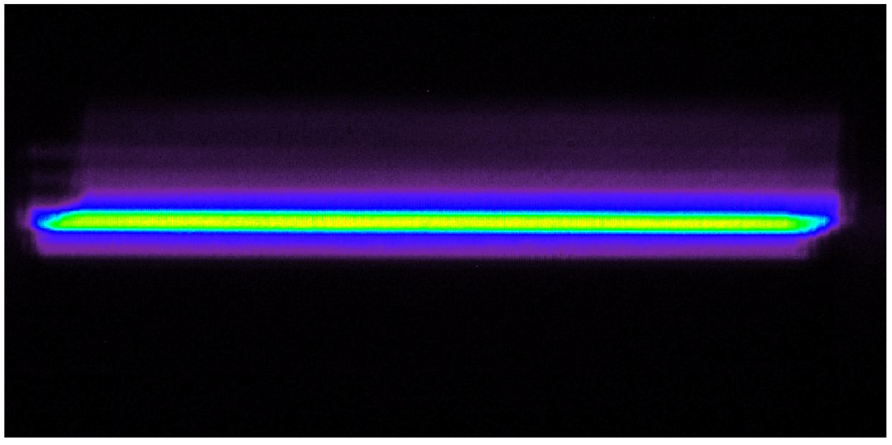
3. Micro-Cylindrical Lens Array Homogenizer
Beam shaping is a process of redistributing the far-field incoherent distribution of diode stacks. Micro-cylindrical lens array homogenizer belongs to beam integrators, which are insensitive to alignment and beam size of diode stacks. Due to a fairly large spectral bandwidth of up to 3 nm and the widely extended emitting area, the diode stacks are nearly incoherent temporally and incoherent spatially across the diode stack. The near-field distribution across the slow direction is relatively flat-topped with minimal rippling from incoherent superposition between diode emitters. In the fast direction, the emitters are similar to completely incoherent or partially coherent extended sources. For diode lasers with a large divergence angle and low coherence, interference is no longer a problem with beam integrators.
A micro-cylindrical lens array homogenizer is especially appropriate for spatially incoherent diode stack sources. From a ray optics perspective, the slow direction of diode stacks produces a wavefront over a range of field angles on the micro-cylindrical lens apertures. The first micro-cylindrical lens array segments the beam into an array of beamlets and focuses the beamlets onto the second micro-cylindrical lens array. The incident optical radiation from each lenslet of the first array must be confined within the corresponding sub-aperture of the second array. The spacing between the two microlens arrays is equal to the effective focal length of the second microlens. Finally, the Fourier lens overlaps these sub-aperture images on the target to form one integrated image of the sub-apertures of the first micro-cylindrical lens array. The homogeneity of the pumping line is not sensitive to the probabilistic failure and aging of each emitter.
Based on ABCD-matrix formalism, a simple design rule was established as shown in Figure 4. The position of the first micro-cylindrical lens array coincides with the object focal plane of the second micro-cylindrical lens array. The target plane coincides with the focal plane of the Fourier lens. Equation (1) describes the tracing process of an incoming ray incident to the n-th micro-cylindrical lens array. Note that the height and angle of the incident ray are relative to the local coordinate system:
where fL was the focal length of the micro-cylindrical lens, pL was the diameter of the micro-cylindrical lens, was the distance between the second micro-cylindrical lens and the Fourier lens, was the focal length of the Fourier lens, Rearranging Equation (1) leads to Equation (2) giving simple expressions for ray height and angle in the image plane:
Figure 4.
Micro-cylindrical lens array homogenizer.
The first row of Equation (2) describes the overlapped image of the first micro-cylindrical lens array with a magnification of −F/f. The ray height in the image plane is independent of the distance between the second micro-cylindrical lens array and the Fourier lens. Some key parameters for the micro-cylindrical lens array homogenizer are shown in the following Table 1.
Table 1.
Key parameters for the micro-cylindrical lens array homogenizer.
To obtain a larger depth of focus, the six-bar in the fast direction was reshaped by a cylindrical telescope system with a 2× ratio as shown in Figure 5. The incident beam was segmented into an array of beamlets by the first micro-cylindrical lens array and focused onto the second micro-cylindrical lens array. A real image with dimensions of 12 × 0.4 mm2 was generated inside the Nd: YAG by the Fourier lens. Furthermore, to show the shape and intensity distribution of the pump spot in the laser crystal more vividly, the simulation software is used to simulate it. As shown in Figure 6, this homogeneous line-shaped pumping beam showed a top-hat intensity along the line direction and a Gaussian intensity distribution across the line. The geometric length of this pumping system is about 140 mm. Compared with the traditional principle of waveguide homogenization, this new method achieves short system length while maintaining higher homogenization performance. Experimental data of the pumping line at the center of the crystal is shown in Figure 7.
Figure 5.
Micro-cylindrical lens array homogenizer in fast direction (above); in slow direction (below).
Figure 6.
Intensity of the pumping line at the center of the slab crystal.
Figure 7.
Experimental data of the intensity of the pumping line at the center of the slab crystal.
4. Laser Dynamics Modeling
Based on the theory of rate equations, laser parameters such as pulse energy, peak power density, and pulse width can be optimized. However, the intracavity photon density and the inversion density of the pumped medium have always made use of the uniform or Gaussian distribution in space. For Innoslab lasers, in the fast axis (perpendicular to the pumping line), the distribution is Gaussian, while in the slow axis (across the pumping line), the distribution is uniform. The individual transverse spatial distributions of Innoslab lasers must be integrated over all space. The definition of the coordinate system is shown in Figure 8. The intracavity photon density and the inversion density are assumed to be separable in time and space, given by
where is the average laser mode radius, is the average width of the pump beam in the fast axis, and are the time-dependent amplitude along the axis, the rate equations from John J. Degnan [19] now considering the spatial variation of the laser mode and pumping beam are:
where is the effective stimulated emission cross-section, is the crystal length in the z-axis, is the round trip time of the resonator, is the lifetime of the photon, is the inversion reduction factor characterizing the reduction in inversion density owing to the stimulated emission of a single photon. Substitute (3) and (4) into (5) and (6), and the integral intervals are respectively the entire cavity mode and the pump region:
Figure 8.
The model of slab crystal; the coordinate system is established as shown in the figure.
The limit on the z integral of Equation (7) covers the optical cavity length while the limit on the z integral of Equation (8) covers the length of the laser crystal. The limit on the x integral runs over the slab width . Due to the Gaussian distribution, the y integral limit extends to infinity. We now define and . The above equations finally become:
To calculate the peak power and output energy , the total photon density is integrated over the entire optical volume of the cavity, then throughout the pulse:
For high repetition rate pulse oscillators, the pulse interval time determines the pumping time and thus the output energy. Given CW and uniform axial pumping, the initial value of the axial inversion density is given:
where is the incident pumping power, is the optical shaping efficiency, is the effective absorption efficiency, is the ratio of laser photon energy to pump photon energy, is the quantum efficiency of the non-radiative transitions, is the upper laser level lifetime, and is the repetition rate.
To verify the optimum output coupling, the above equations are numerically calculated based on the standard Runge-Kutta fourth-order technique. Figure 9 shows the output energy (solid curve) and the FWHM pulse width (dashed curve) against the effective output coupler reflectivity when the repetition rate is 1 kHz. As the effective output coupler reflectivity increases, the pulse energy increases first and then decreases, while the pulse width decreases first and then increases. There must be an optimum effective output coupling so that the pulse energy is largest and the pulse width is smallest. Considering the peak power density in the resonator and damage threshold, the effective output coupling is set at 70%, consistent with the radii of curvature of the highly reflective rear mirror and the output coupling mirror. The output pulse energy is about 16.5 mJ at 1 kHz.
Figure 9.
The output energy (solid curve) and the FWHM pulse width (dashed curve) against the effective output coupler reflectivity when the repetition rate is 1 kHz.
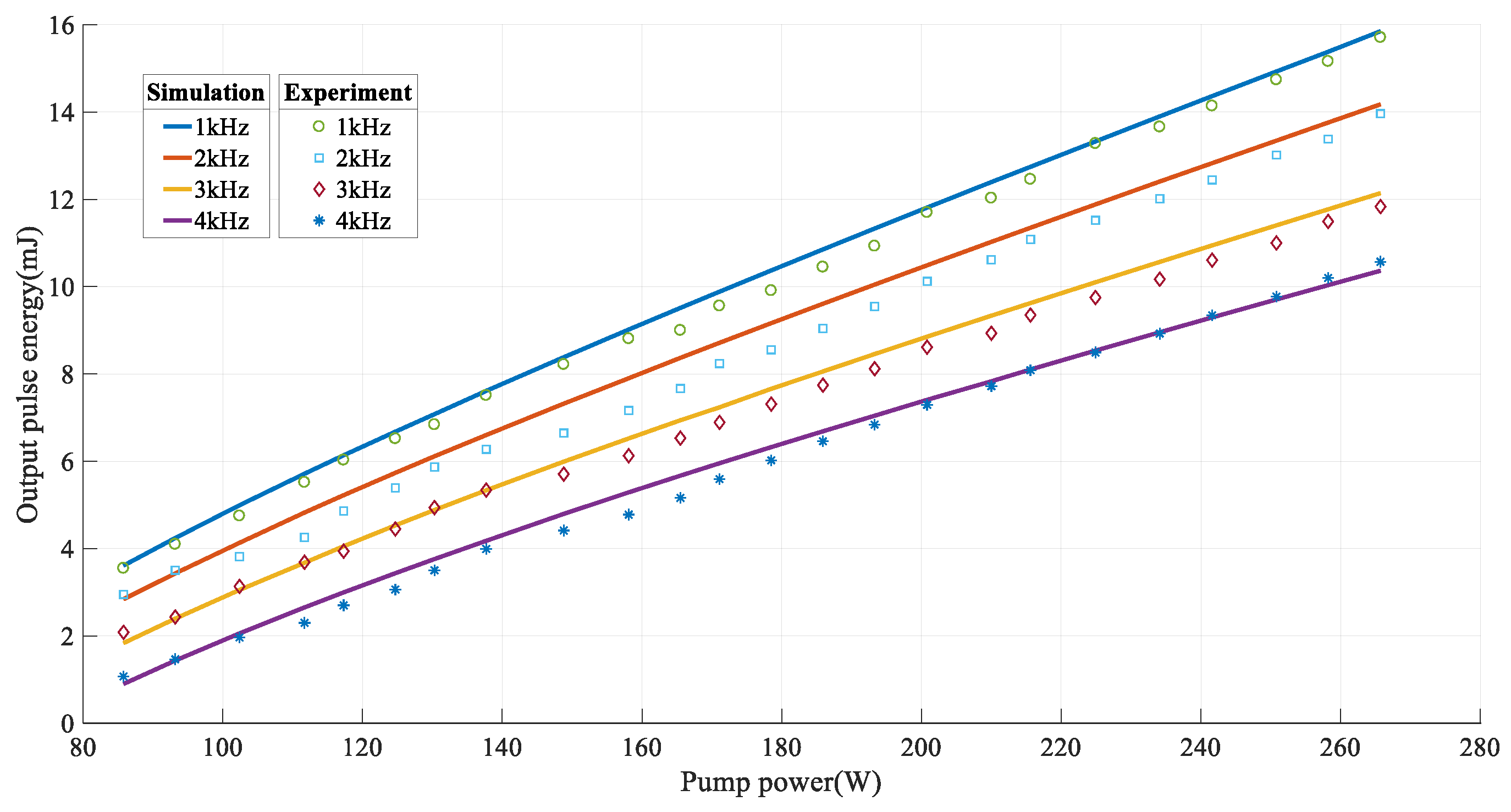
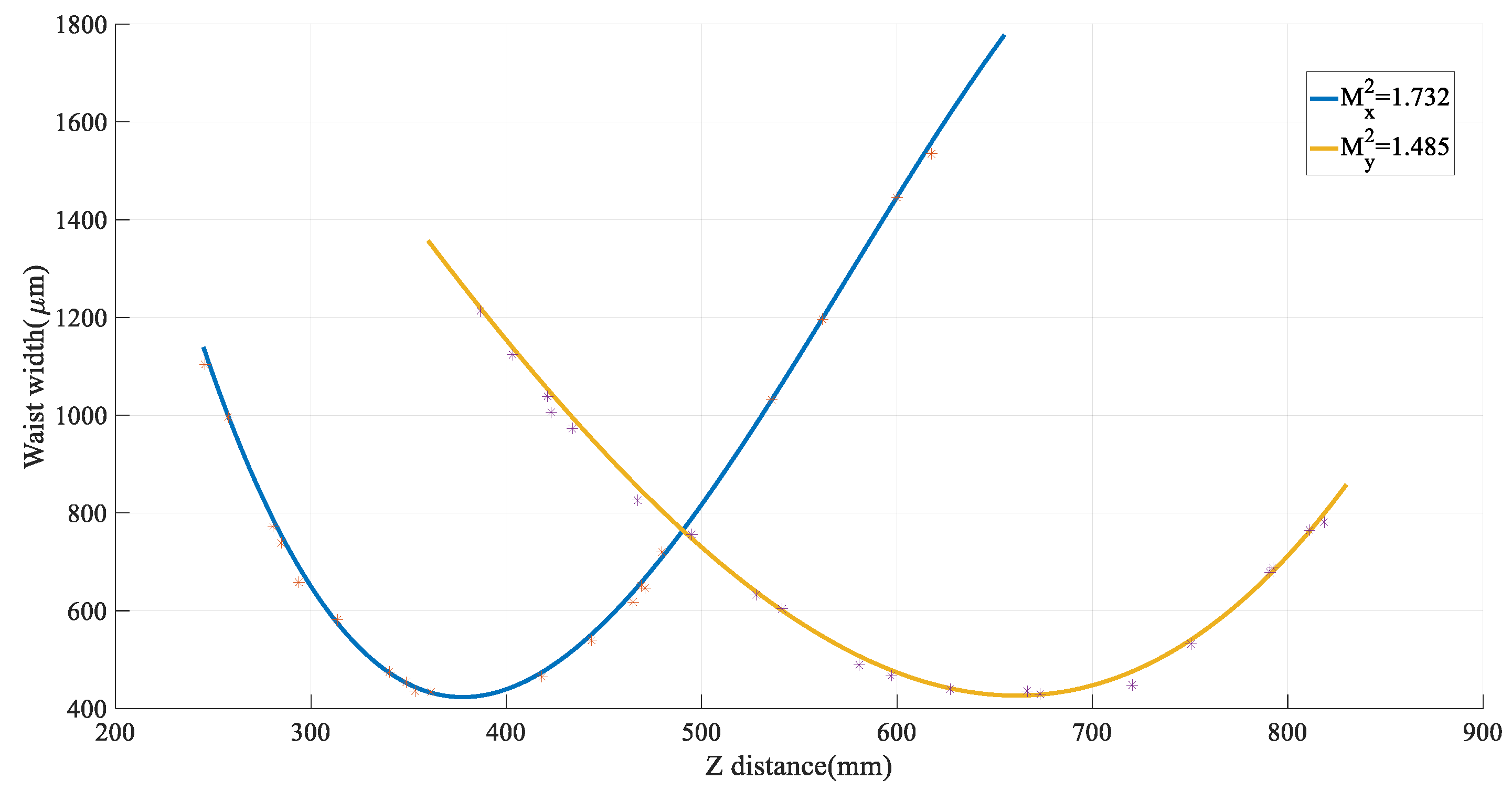
5. Results and Discussion
The diode stacks are composed of six vertically arranged bars with 25 emitters in the slow axis. After the fast axis collimation, the residual divergence angle is less than 0.5°. The bar-to-bar spacing is 1.9 mm, which causes non-continuity of the intensity. The far-field pattern exhibits light and dark stripes in the fast axis, while the pattern in the slow axis is superimposed by various high-order modes, as shown in Figure 10a.
Figure 10.
(a) the far field pattern of the diode stacks with fast axis collimation; (b) the experimental results of the pump shaping based on a micro-cylindrical array lens.
For partially end-pumping Innoslab lasers, the following requirements are required: (1) The distribution in the slow axis is uniform to achieve a one-dimensional heat distribution and eliminate the thermally induced birefringence. The length of the pumping line is approximately the same as the width of the slab crystal . (2) The size of the Gaussian distribution in the fast axis is about 0.4 mm@1/e2 to achieve a good mode matching with the optical cavity mode. Two soft rulers were placed close to the pumping line in the fast and slow axes. Then the entire optical bench is imaged with a telecentric lens. The length scale conversion between the soft ruler and the image is 744, 1 mm of the soft ruler corresponding to 744 μm of the image. The size of the pumping line inside the slab crystal is about 12 × 0.4 mm2, as shown in Figure 10b.
The output pulse energy as a function of different average pump power at the repetition rates of 1 kHz, 2 kHz, 3 kHz, and 4 kHz was shown in Figure 11. The results show that the output power increased approximately linearly with the pump power when the repetition frequency is constant. This means that the output power is not saturated. The optical shaping efficiency was about 80%, and the effective absorption efficiency was about 85% of the incident pump power. At the maximum pump power of 260 W, a maximum pulse energy of 10 mJ or output power of 40 W at 4 kHz was obtained. The optical-to-optical efficiency from absorbed pump power to laser output was about 22.6%, and the slope efficiency was 30%.
Figure 11.
The output pulse energy at different repetition rates against the pump power.
When the repetition frequency is 1 kHz, the change of the pulse width against the pump power is shown in Figure 12. When the pump power increases, the pulse width gradually decreases to 8.5 ns. Based on α-BBO, the laser beam was polarized along the unstable direction. Because the output coupler M2 is planar in the y direction, the beam waist in the y direction was always on the output mirror. To evaluate the spatial characteristics of the Innoslab laser, the beam quality of the output laser at a repetition rate of 1 kHz was measured by a laser beam analyzer (Ophir, Jerusalem, Israel, BeamSquared PY-M). The measurement results are shown in Figure 13. The beam quality M2 factors in the unstable and stable directions were 1.732 and 1.485, respectively. The pulse width, the near field, and the far field of the output laser are shown in Figure 14.
Figure 12.
The pulse width against the pump power is at 1 kHz.
Figure 13.
The beam quality factor of M2.
Figure 14.
Left: The pulse width of the output laser. Right: (a) the near field of the output laser; (b) the far field of the output laser.
6. Conclusions
We demonstrate a partially end-pumped Innoslab laser based on a micro-cylindrical lens array homogenizer and modified rate equations. A flat-top pumping line with a size of 12 × 0.4 mm2 with uniformity greater than 95% was shown by ray tracing technology. Modified rate equations considering transverse spatial distributions of the intracavity photon density and the inversion density were numerically solved. The optimum output coupler reflectivity, the output pulse energy, and the pulse width were well experimentally predicted. When the pump power is 260 W, the maximum average output power of 40 W was generated at 4 kHz. The M2 factors of beam quality in unstable and stable directions are 1.732 and 1.485, respectively. This method provides a new idea and method for the pump light homogenization shaping of lasers based on micro-cylindrical lens array homogenizers. The agreement between the simulation and the experimental data shows the effectiveness of the modified rate model in predicting the performance of Innoslab lasers.
Author Contributions
Conceptualization, X.S. and T.Z.; methodology, X.S.; software, X.S. and J.C.; validation, Y.W., P.L. and G.C.; formal analysis, X.S., L.S. and X.Z.; investigation, X.Z. and X.C.; resources, Y.F.; data curation, X.S.; writing—original draft preparation, X.S. and Y.X.; writing—review and editing, X.S. and X.Z; visualization, X.Z; supervision, H.G. and G.F.; project administration, T.Z.; funding acquisition, T.Z. All authors have read and agreed to the published version of the manuscript.
Funding
This research has been supported by the National Key R&D Program of China (2022YFC3700400, 2022YFC3704000), the Second Tibetan Plateau Scientific Expedition and Research Program (STEP) (2019QZKK0605, 2019QZKK0100), the Key R&D Project in Shanxi Province (202202150401009), and pre-research projects on civil aerospace technology (D020305).
Institutional Review Board Statement
No applicable.
Informed Consent Statement
No applicable.
Data Availability Statement
All data involved is contained within this article.
Conflicts of Interest
The authors declare no conflicts of interest.
References
- Du, K.M.; Li, D.J.; Shi, P.; Fu, S.J.; Haas, C.R.; Liu, X.M.; Qi, B.S.; Chen, J.; Schell, A. The unique features and application examples of INNOSLAB lasers. In Proceedings of the ICALEO® 2009: 28th International Congress on Laser Materials Processing, Laser Microprocessing and Nanomanufacturing, Orlando, FL, USA, 2–5 November 2009; AIP Publishing: New York, NY, USA, 2009; pp. 861–867. [Google Scholar]
- Du, K. Unique performances and favourable applications of INNOSLAB lasers. In Proceedings of the SPIE—Solid State Lasers XVIII: Technology and Devices, San Jose, CA, USA, 25–29 January 2009; Volume 7193, pp. 607–616. [Google Scholar]
- Russbueldt, P.; Hoffmann, D.; Hofer, M.; Lohring, L.; Luttmann, J.; Meissner, A.; Wei, J. Innoslab amplifiers. IEEE J. Sel. Top. Quantum Electron. 2014, 21, 447–463. [Google Scholar] [CrossRef]
- Poprawe, R.; Gillner, A.; Hoffmann, H.D.; Kaierle, S.; Loosen, P.; Meiners, W.; Noll, R.; Willenborg, E. Disk, fiber, rod, slab: New laser concepts open new application perspectives. In Proceedings of the SPIE 7138, Photonics, Devices, and Systems IV, Prague, Czech Republic, 27–29 September 2008; Volume 7138, pp. 47–58. [Google Scholar]
- Li, D.J.; Ma, Z.; Haas, R.; Schell, A.; Simon, J.; Zhu, P.; Shi, P.; Du, K.M. Diode-end-pumped double Nd: YLF slab laser with high energy, short pulse width, and diffraction-limited quality. Opt. Lett. 2008, 33, 1708–1710. [Google Scholar] [CrossRef] [PubMed]
- Li, D.J.; Ma, Z.; Haas, R.; Schell, A.; Diart, R.; Shi, P.; Hu, P.X.; Loosen, P.; Du, K.M. Diode-pumped efficient slab laser with two Nd: YLF crystals and second-harmonic generation by slab LBO. Opt. Lett. 2007, 32, 1272–1274. [Google Scholar] [CrossRef] [PubMed]
- Ma, Z.; Li, D.J.; Hu, P.X.; Schell, A.; Shi, P.; Haas, R.; Wu, N.L.; Du, K.M. Monolithic Nd: YVO4 slab oscillator-amplifier. Opt. Lett. 2007, 32, 1262–1264. [Google Scholar] [CrossRef] [PubMed]
- Mao, Y.F.; Zhang, H.L.; Cui, J.H.; Yuan, J.H.; Hao, X.L.; Yi, J. 25 mJ, 5 KHz, 3 ns, Nd: YAG discrete path slab amplifier using a hybrid resonator. Appl. Opt. 2017, 56, 2741–2744. [Google Scholar] [CrossRef] [PubMed]
- Sang, S.H.; Zhang, H.L.; Mao, Y.F.; Zhang, X.; Zou, J.Y.; Xin, J.G.; Xing, J.C.; Jiang, Y. Compact, high-average-power, nanosecond multi-pass Nd: YVO4 Innoslab amplifier. Appl. Phys. B 2015, 121, 131–134. [Google Scholar] [CrossRef]
- Mao, Y.F.; Zhang, H.L.; Zhang, X.L.; Hao, J.H.; Xing, J.C.; Xin, J.G.; Yi, J. 8.4 mJ, 10kHz, 3.6 ns, Nd: YVO4 slab amplifier. Opt. Express 2016, 24, 11017–11022. [Google Scholar] [CrossRef] [PubMed]
- Liu, X.; Li, D.J.; Shi, P.; Haas, R.; Du, K.M. Highly efficient third-harmonic generation with electro-optically Q-switched diode-end-pumped Nd: YVO4 slab laser. Opt. Commun. 2007, 272, 192–196. [Google Scholar] [CrossRef]
- Li, D.J.; Fu, S.J.; Liu, X.M.; Shi, P.; Chen, J.; Shell, A.; Qi, B.S.; Haas, C.R.; Wang, J.X.; Du, K.M. Recent progresses in INNOSLAB lasers and their harmonic generation. In Solid State Lasers XIX—Technology and Devices; SPIE: Philadelphia, PA, USA, 2010; Volume 7578. [Google Scholar]
- Schnitzler, C.; Schmidt, G.; Du, K.M.; Loosen, P.; Poprawe, R.; Marshall, C. Improving the brightness of a diode end pumped slab laser by a new pumping scheme. In Topical Meeting on Advanced Solid-State Lasers; Optica Publishing Group: San Jose, CA, USA, 2001; Volume 50, pp. 5–10. [Google Scholar]
- Slimani, M.; Liu, J.; Xin, J.; Chen, J. Beam shaping of high power diode laser stack into homogeneous line. Front. Optoelectron. 2014, 7, 102–106. [Google Scholar] [CrossRef]
- Duan, Y.; Song, C.; Mao, Y. >300 W laser-diode dual-end-pumped Nd: YVO4 Innoslab laser. Laser Phys. 2016, 26, 095006. [Google Scholar] [CrossRef]
- Liu, L.; Zhou, S.H.; Liu, Y.; Wang, Z.; Wang, G.; Zhao, H. The 5.2kW Nd: YAG Slab Amplifier Chain Seeded by Nd: YVO4 Innoslab Laser. Chin. Phys. Lett. 2017, 34, 064202. [Google Scholar] [CrossRef]
- Gao, Q.; Zhang, H.; Fayyaz, J. Laser diode partially end-pumped electro-optically Q-switched Yb: YAG slab laser. Chin. Opt. Lett. 2019, 17, 111405. [Google Scholar] [CrossRef]
- Kanchanavaleerat, E.; Cochet-Muchy, D.; Kokta, M.; Stone-Sundberg, J.; Sarkies, P.; Sarkies, J.; Sarkies, J. Crystal growth of high doped Nd: YAG. Opt. Mater. 2004, 26, 337–341. [Google Scholar] [CrossRef]
- Degnan, J.J. Theory of the Optimally Coupled Q-Switched Laser. IEEE J. Quantum Electron. 1989, 25, 214–220. [Google Scholar] [CrossRef]
Disclaimer/Publisher’s Note: The statements, opinions and data contained in all publications are solely those of the individual author(s) and contributor(s) and not of MDPI and/or the editor(s). MDPI and/or the editor(s) disclaim responsibility for any injury to people or property resulting from any ideas, methods, instructions or products referred to in the content. |
© 2024 by the authors. Licensee MDPI, Basel, Switzerland. This article is an open access article distributed under the terms and conditions of the Creative Commons Attribution (CC BY) license (https://creativecommons.org/licenses/by/4.0/).


